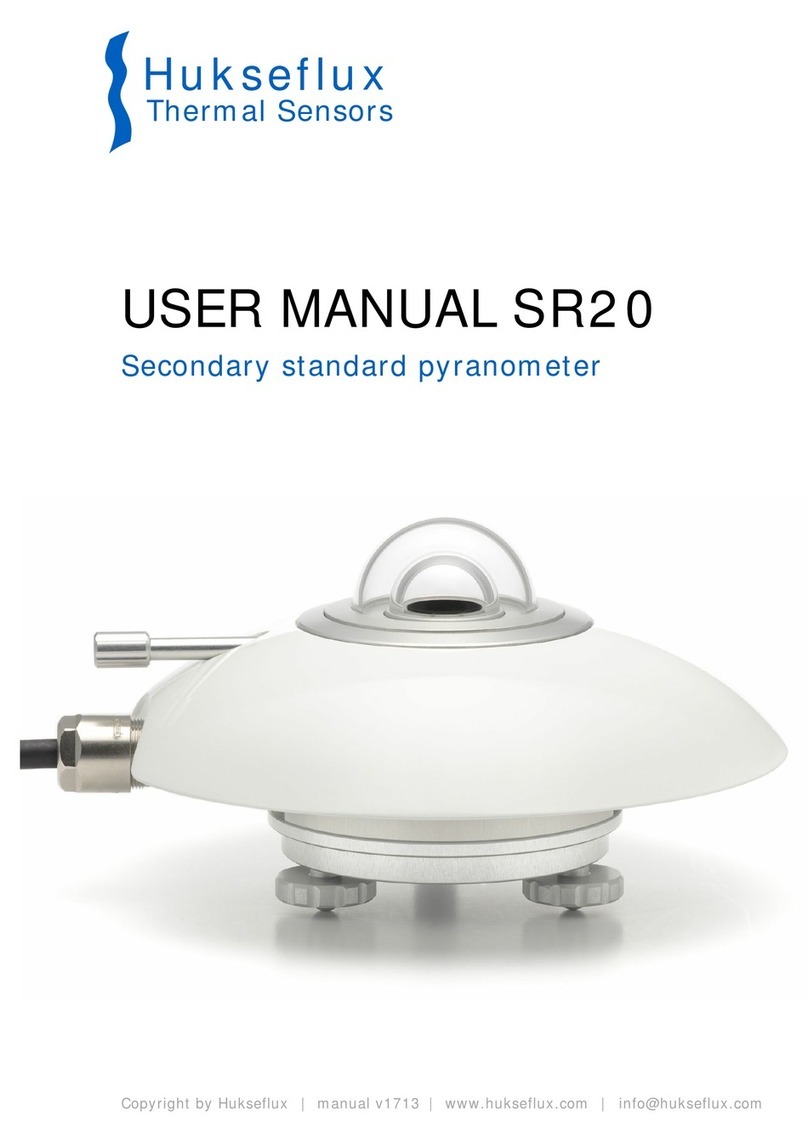
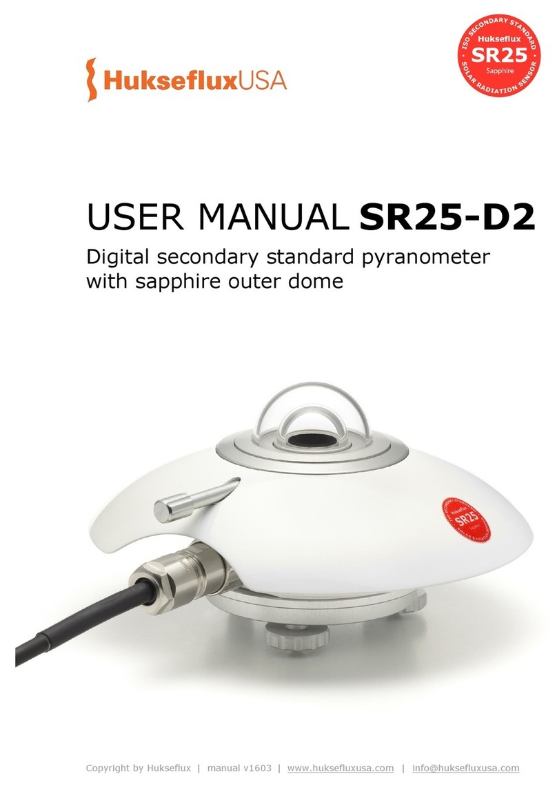
Hukseflux SR20-D2 User manual

SR20-D2 manual v2215 2/72
Warning statements
Putting more than 30 Volt across the sensor wiring
of the main power supply can lead to permanent
damage to the sensor.
Putting more than 40 Volt across the sensor wiring
of the current loop (4 to 20 mA) can lead to
permanent damage to the sensor.
For proper instrument grounding: use SR20-D2 with
its original factory-made SR20-D2 cable.
Using the same Modbus address for more than one
device will lead to irregular behaviour of the entire
network.
Your data request may need an offset of +1 for each
SR20-D2 register number, depending on processing
by the network master. Consult the manual of the
device acting as the local master.

SR20-D2 manual v2215 3/72
Contents
Warning statements 2
Contents 3
List of symbols 5
Introduction 6
1Ordering and checking at delivery 9
1.1 Ordering SR20-D2 9
1.2 Included items 9
1.3 Quick instrument check 10
2Instrument principle and theory 11
3Specifications of SR20-D2 14
3.1 Specifications of SR20-D2 14
3.2 Dimensions of SR20-D2 18
4Standards and recommended practices for use 19
4.1 Classification standard 19
4.2 General use for solar radiation measurement 19
4.3 General use for sunshine duration measurement 19
4.4 Specific use for outdoor PV system performance testing 20
4.5 Specific use in meteorology and climatology 20
5Installation of SR20-D2 21
5.1 Site selection and installation 21
5.2 Installation of the sun screen 22
5.3 Electrical connection of SR20-D2: wiring diagram 23
5.4 Grounding and use of the shield 23
5.5 Using SR20-D2’s 4 to 20 mA output 24
5.6 Connecting to an RS-485 network 26
5.7 Connecting to a PC 28
6Communication with SR20-D2 29
6.1 PC communication: Sensor Manager software 29
6.2 Network communication: function codes, registers, coils 34
6.3 Network communication: getting started 42
6.4 Network communication: example master request to SR20-D2 43
7Making a dependable measurement 46
7.1 The concept of dependability 46
7.2 Reliability of the measurement 47
7.3 Speed of repair and maintenance 48
7.4 Uncertainty evaluation 48
8Maintenance and trouble shooting 51
8.1 Recommended maintenance and quality assurance 51
8.2 Trouble shooting 52
8.3 Calibration and checks in the field 53
8.4 Data quality assurance 54
9Appendices 56
9.1 Appendix on cable extension / replacement 56
9.2 Appendix on tools for SR20-D2 57
9.3 Appendix on spare parts for SR20-D2 58
9.4 Appendix on standards for classification and calibration 59
9.5 Appendix on calibration hierarchy 60
9.6 Appendix on meteorological radiation quantities 61
9.7 Appendix on ISO and WMO classification tables 62
SR20-D2 manual v2215 5/72
List of symbols
Quantities Symbol Unit
Voltage output U V
Sensitivity S V/(W/m2)
Temperature T °C
Solar irradiance E W/m2
Solar radiant exposure H W∙h/m2
Time in hours h h
Temperature coefficient a 1/°C²
Temperature coefficient b 1/°C
Temperature coefficient c -
Output of 4-20 mA current loop I A
Transmitted range of 4-20 mA output r W/m2
(see also appendix 9.6 on meteorological quantities)
Subscripts
Not applicable

SR20-D2 manual v2215 6/72
Introduction
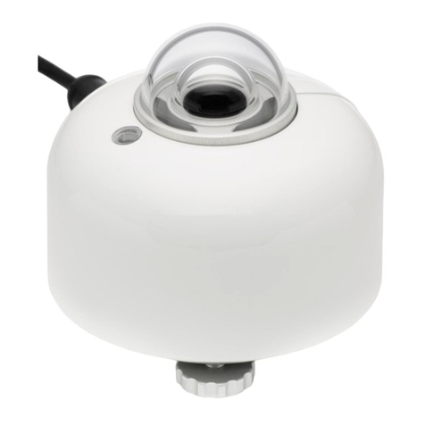
SR20-D2 is a solar radiation sensor of the highest category in the ISO 9060 classification
system: secondary standard. SR20-D2 is designed for the solar PV industry, offering two
types of commonly used irradiance outputs: digital via Modbus RTU over RS-485 and
analogue 4-20 mA (current loop). These industry standards allow for easy data
acquisition, easy read-out and error-free instrument exchange when using SR20-D2.
SR20-D2 measures the solar radiation received by a plane surface, in W/m2, from a 180o
field of view angle. It is employed where the highest measurement accuracy is required.
This user manual covers SR20-D2 use. Specifications of SR20-D2 differ from
those of model SR20. For SR20 use, consult the separate SR20 user manual.
Individually tested for temperature and directional response, SR20-D2 is the most
accurate digital secondary standard pyranometer available. Its benefits:
• Digital output: easy implementation and servicing
• Best-in-class temperature response < ± 0.4 % (-30 to +50 °C), best “zero offset a”
and best calibration uncertainty
• Included in delivery as required by ISO 9060: test certificates for temperature
response and directional response
•Re-calibration registers fully accessible to users
In order to improve overall measurement accuracy, Hukseflux effectively targeted two
major sources of measurement uncertainty: calibration and “zero offset a”. In addition,
SR20-D2 has a negligible temperature response. All are best in class. The temperature
response of every individual instrument is tested and corrected onboard by the
instrument electronics, using a second degree polynomial. SR20-D2’s low temperature
dependence makes it the ideal candidate for use under very cold and very hot conditions.
Figure 0.1 SR20-D2 digital secondary standard pyranometer

SR20-D2 manual v2215 7/72
SR20-D2 pyranometer employs a state-of-the-art thermopile sensor with black coated
surface, two domes and an anodised aluminium body. The connector, desiccant holder
and sun screen fixation are very robust and designed for long term industrial use.
SR20-D2 uses a high-end 24-bit A/D converter. All parts are specified for use across
SR20-D2’s entire rated operating temperature range. SR20-D2 offers two types of
outputs: digital output via Modbus RTU over 2-wire RS-485 and analogue 4-20 mA
output (current loop).
For communication between a PC and SR20-D2, the Hukseflux Sensor Manager can be
used. It allows the user to plot and export data, and change the SR20-D2 Modbus
address and its communication settings.
Figure 0.2 User interface of the Sensor Manager
SR20-D2 is designed for use in SCADA (Supervisory Control And Data Acquisition)
systems, supporting Modbus RTU (Remote Terminal Unit) protocol over RS-485. In these
networks the sensor operates as a slave. SCADA systems are often implemented in
photovoltaic solar energy (PV) systems and meteorological networks. Using SR20-D2 in a
network is easy. Once it has the correct Modbus address and communication settings and
is connected to a power supply, the instrument can be used in RS-485 networks. A
typical network will request the irradiance (registers 2 + 3) and temperature data
(register 6) every 1 second, and eventually store the averages every 60 seconds. How to
issue a request, process the register content and convert it to useful data is described in
the paragraphs about network communication. The user should have sound knowledge of
the Modbus communication protocol when installing sensors in a network.

SR20-D2 manual v2215 8/72
The instrument should be used in accordance with the recommended practices of ISO,
WMO and ASTM.
The recommended calibration interval of pyranometers is 2 years. The registers
containing the applied sensitivity and the calibration history of SR20-D2 are fully
accessible for users. This allows the user to choose his own local calibration service. The
same feature may be used for remotely controlled re-calibration of pyranometers in the
field. Ask Hukseflux for information on this feature and on ISO and ASTM standardised
procedures for field calibration.
Suggested use for SR20-D2:
•PV system performance monitoring
•all networks with regular instrument exchange
•scientific meteorological observations
•reference instrument for comparison
•extreme climates (tropical / polar)
The ASTM E2848 “Standard Test Method for Reporting Photovoltaic Non-Concentrator
System Performance” (issued end 2011) confirms that a pyranometer is the preferred
instrument for PV system performance monitoring. SR20-D2 pyranometer complies with
the requirements of this standard. For more information, see our pyranometer selection
guide.
WMO has approved the “pyranometric method” to calculate sunshine duration from
pyranometer measurements in WMO-No. 8, Guide to Meteorological Instruments and
Methods of Observation. This implies that SR20-D2 may be used, in combination with
appropriate software, to estimate sunshine duration. This is much more cost-effective
than using a dedicated sunshine duration sensor. Ask for our application note.

SR20-D2 manual v2215 9/72
1Ordering and checking at delivery
1.1 Ordering SR20-D2
The standard configuration of SR20-D2 is with 5 metres cable.
Common options are:
•Longer cable (in multiples of 5 m). Specify total cable length.
•Five silica gel bags in an air-tight bag for SR20-D2 desiccant holder. Specify order
number DC01.
•Adapted transmitted range for 4-20 mA output. Standard setting is 4 mA at 0 W/m2
and 20 mA at 1600 W/m2. Specify preferred range setting.
•VU01 ventilation unit
1.2 Included items
Arriving at the customer, the delivery should include:
•pyranometer SR20-D2
•sun screen
•cable of the length as ordered
•calibration certificate matching the instrument serial number
•product certificate matching the instrument serial number
(including temperature response test report and directional response test report for
the individual instrument)
•any other options as ordered
Please store the certificates in a safe place.

SR20-D2 manual v2215 10/72
1.3 Quick instrument check
A quick test of the instrument can be done by connecting it to a PC and installing the
Sensor Manager software. See the chapters on installation and PC communication for
directions.
1. At power–up the signal may have a temporary output level different from zero; an
offset. Let this offset settle down.
2. Check if the sensor reacts to light: expose the sensor to a strong light source, for
instance a 100 W light bulb at 0.1 m distance. The signal should read > 100 W/m2now.
Darken the sensor either by putting something over it or switching off the light. The
instrument irradiance output should go down and within one minute approach 0 W/m2.
3. Remove the sun screen, (see chapter on installation of the sun screen). Inspect the
bubble level.
4. Inspect the instrument for any damage.
5. Inspect if the humidity indicator is blue. Blue indicates dryness. The colour pink
indicates it is humid: in the latter case replace the desiccant (see chapter on
maintenance).
6. Check the instrument serial number as indicated by the software against the label on
the instrument and against the certificates provided with the instrument.

SR20-D2 manual v2215 11/72
2Instrument principle and theory
Figure 2.1 Overview of SR20-D2:
(1) cable (standard length 5 metres, optional longer cable)
(2) fixation of sun screen (thumb screw)
(3) inner dome
(4) thermal sensor with black coating
(5) outer dome
(6) sun screen
(7) humidity indicator
(8) desiccant holder
(9) levelling feet
(10) bubble level
(11) connector
1
2
34
5
6
7
8
9
10
11

SR20-D2 manual v2215 12/72
SR20-D2’s scientific name is pyranometer. A pyranometer measures the solar radiation
received by a plane surface from a 180 ° field of view angle. This quantity, expressed in
W/m2, is called “hemispherical” solar radiation. The solar radiation spectrum extends
roughly from 285 to 3000 x 10-9 m. By definition a pyranometer should cover that
spectral range with a spectral selectivity that is as “flat” as possible.
In an irradiance measurement by definition the response to “beam” radiation varies with
the cosine of the angle of incidence; i.e. it should have full response when the solar
radiation hits the sensor perpendicularly (normal to the surface, sun at zenith, 0 ° angle
of incidence), zero response when the sun is at the horizon (90 ° angle of incidence, 90 °
zenith angle), and 50 % of full response at 60 ° angle of incidence.
A pyranometer should have a so-called “directional response” (older documents mention
“cosine response”) that is as close as possible to the ideal cosine characteristic.
In order to attain the proper directional and spectral characteristics, a pyranometer’s
main components are:
•a thermal sensor with black coating. It has a flat spectrum covering the 200 to 50000
x 10-9 m range, and has a near-perfect directional response. The coating absorbs all
solar radiation and, at the moment of absorption, converts it to heat. The heat flows
through the sensor to the sensor body. The thermopile sensor generates a voltage
output signal that is proportional to the solar irradiance.
•in case of SR20-D2 the analogue thermopile voltage is converted by the instrument
electronics to a digital signal. In this process also the temperature dependence of the
thermopile is compensated. SR20-D2 uses a high-end 24-bit A/D converter.
•a glass dome. This dome limits the spectral range from 285 to 3000 x 10-9 m (cutting
off the part above 3000 x 10-9 m), while preserving the 180 ° field of view angle.
Another function of the dome is that it shields the thermopile sensor from the
environment (convection, rain).
•a second (inner) glass dome: For a secondary standard pyranometer, two domes are
used, and not one single dome. This construction provides an additional “radiation
shield”, resulting in a better thermal equilibrium between the sensor and inner dome,
compared to using a single dome. The effect of having a second dome is a strong
reduction of instrument offsets.
Pyranometers can be manufactured to different specifications and with different levels of
verification and characterisation during production. The ISO 9060 - 1990 standard, “Solar
energy - specification and classification of instruments for measuring hemispherical solar
and direct solar radiation”, distinguishes between 3 classes; secondary standard (highest
accuracy), first class (second highest accuracy) and second class (third highest
accuracy).
From second class to first class and from first class to secondary standard, the achievable
accuracy improves by a factor 2.

SR20-D2 manual v2215 13/72
Figure 2.2 Spectral response of the pyranometer compared to the solar spectrum. The
pyranometer only cuts off a negligible part of the total solar spectrum.
Figure 2.3 Directional response of a SR20-D2 pyranometer of 4 azimuth angles, compared
to secondary standard limits
0
0.2
0.4
0.6
0.8
1
1.2
100 1000 10000
relative spectral content /
response [arbitrary units]
wavelength [x 10-9 m]
solar radiation
pyranometer
response
-4%
-2%
0%
2%
4%
020 40 60 80
Deviation from ideal cosine behaviour
[%]
zenith angle [°]
North
East
South
West
ISO secondary
standard
directional
response limit

SR20-D2 manual v2215 14/72
3Specifications of SR20-D2
3.1 Specifications of SR20-D2
SR20-D2 measures the solar radiation received by a plane surface from a 180 ° field of
view angle. This quantity, expressed in W/m2, is called “hemispherical” solar radiation.
SR20-D2 offers irradiance in W/m2as a digital output and as a 4-20 mA output. It must
be used in combination with suitable power supply and a data acquisition system which
uses the Modbus communication protocol over RS-485 or one that is capable of handling
a 4-20 mA current loop signal. The instrument is classified according to ISO 9060 and
should be used in accordance with the recommended practices of ISO, IEC, WMO and
ASTM.
Table 3.1.1 Specifications of SR20-D2 (continued on next pages)
SR20-D2 MEASUREMENT SPECIFICATIONS:
LIST OF CLASSIFICATION CRITERIA OF ISO 9060*
ISO classification (ISO 9060: 1990)
secondary standard pyranometer
WMO performance level (WMO-No. 8,
seventh edition 2008)
high quality pyranometer
Response time (95 %)
4.5 s
Zero offset a (response to 200 W/m2
net thermal radiation)
5 W/m2 unventilated
2.5 W/m
2
ventilated
Zero offset b (response to 5 K/h
change in ambient temperature)
< ± 2 W/m2
Non-stability
< ± 0.5 % change per year
Non-linearity
< ± 0.2 % (100 to 1000 W/m2)
Directional response
< ± 10 W/m2
Directional response test of individual
instrument
report included
Spectral selectivity
< ± 3 % (0.35 to 1.5 x 10⁻⁶ m)
Temperature response
< ± 0.4 % (-30 to +50 °C)
Temperature response test of
individual instrument
report included
Tilt response
< ± 0.2 % (0 to 90 ° at 1000 W/m2)
*For the exact definition of pyranometer ISO 9060 specifications see the appendix.

SR20-D2 manual v2215 15/72
Table 3.1.1 Specifications of SR20-D2 (continued)
SR20-D2 ADDITIONAL SPECIFICATIONS
Measurand
hemispherical solar radiation
Measurand in SI radiometry units
irradiance in W/m2
Optional measurand
sunshine duration
Field of view angle
180 °
Output definition
running average over 4 measurements, refreshed
every 0.1 s
Recommended data request interval
1 s, storing 60 s averages
Measurement range
-400 to 4000 W/m2
Zero offset steady state
< ± 0.5 W/m2at 20 °C
< ± 0.8 W/m
2
(-40 to + 80 °C)
Zero offset dynamic / during power up
< 10 W/m2(nominal)
Measurement function / optional
programming for sunshine duration
programming according to WMO guide paragraph
8.2.2
Internal temperature sensor
Analog Devices ADT7310 digital SPI temperature
sensor
Rated operating temperature range
-40 to +80 °C
Spectral range
(20 % transmission points)
285 to 3000 x 10-9 m
Standard governing use of the
instrument
ISO/TR 9901:1990 Solar energy -- Field pyranometers
-- Recommended practice for use
ASTM G183 - 05 Standard Practice for Field Use of
Pyranometers, Pyrheliometers and UV Radiometers
Standard cable length (see options)
5 m
Cable diameter
5.3 x 10⁻³ m
Chassis connector
M16 panel connector, male thread, 10-pole
Chassis connector type
HUMMEL AG 7.840.200.000 panel connector, front
mounting, short version
Cable connector
M16 straight connector, female thread, 10-pole
Cable connector type
HUMMEL AG 7.810.300.00M straight connector,
female thread, for cable 3 to 6 x 10⁻³ m, special
version
Connector protection class
IP67 / IP69 K per EN 60 529 (connected)
Cable replacement
replacement cables with connector can be ordered
separately from Hukseflux
Mounting
2 x M5 bolt at 65 x 10-3 m centre-to-centre distance
on north-south axis, or 1 x M6 bolt at the centre of
the instrument, connection from below under the
bottom plate of the instrument
Levelling
bubble level and adjustable levelling feet are included
Levelling accuracy
< 0.1° bubble entirely in ring
Desiccant
two bags of silica gel, 0.5 g, (35 x 20) mm
Humidity indicator
blue when dry, pink when humid
IP protection class
IP67
Gross weight
approx. 1 kg
Net weight
approx. 0.5 kg
HEATING
Heater
no heating

SR20-D2 manual v2215 16/72
Table 3.1.1 Specifications of SR20-D2 (started on previous pages)
CALIBRATION
Calibration traceability
to WRR
Calibration hierarchy
from WRR through ISO 9846 and ISO 9847, applying
a correction to reference conditions
Calibration method
indoor calibration according to ISO 9847, Type IIc
Calibration uncertainty
< 1.2 % (k = 2)
Recommended recalibration interval
2 years
Reference conditions
20 °C, normal incidence solar radiation, horizontal
mounting, irradiance level 1000 W/m
2
Validity of calibration
based on experience the instrument sensitivity will not
change during storage. During use under exposure to
solar radiation the instrument “non-stability”
specification is applicable.
Adjustment after re-calibration
via a PC, as power user with the Sensor Manager
software. Request “power user” status at the factory
for sensitivity adjustment and for writing the
calibration history data.
MEASUREMENT ACCURACY AND RESOLUTION
Uncertainty of the measurement
statements about the overall measurement
uncertainty can only be made on an individual basis.
see the chapter on uncertainty evaluation
WMO estimate on achievable accuracy
for daily sums (see appendix for a
definition of the measurement conditions)
2 %
WMO estimate on achievable accuracy
for hourly sums (see appendix for a
definition of the measurement conditions)
3 %
Irradiance resolution
0.05 W/m2
Instrument body temperature resolution
7.8 x 10⁻³ °C
Instrument body temperature accuracy
± 0.5 °C
DIGITAL
Digital output
irradiance in W/m2
instrument body temperature in °C
Rated operating voltage range
5 to 30 VDC
Power consumption main supply
< 75 x 10-3 W at 12 VDC
Communication protocol
Modbus over 2-wire RS-485
half duplex
Transmission mode
RTU
System requirements for use with PC
Windows XP and later, USB or RS-232 (COM) port and
connector, RS-485 / USB converter or RS-485 / RS-
232 converter
Software requirements for use with PC
Java Runtime Environment – software
available free of charge at http://www.java.com
User interface on PC
User interface on PC - Hukseflux Sensor Manager
software. Please check
http://www.hukseflux.com/page/downloads
ANALOGUE 4 TO 20 mA
4 to 20 mA output
irradiance in W/m2
Transmitted range
0 to 1600 W/m2
Output signal
4 to 20 x 10-3 A
Standard setting (see options)
4 x 10⁻³ A at 0 W/m2and
20 x 10
-3
A at 1600 W/m
2

SR20-D2 manual v2215 17/72
Table 3.1.1 Specifications of SR20-D2 (started on previous pages)
Principle of 4 to 20 mA output
2-wire current loop. note: 2 additional wires are
needed for the main supply of the sensor
Rated operating voltage range of 4 to 20
mA output
10 to 40 VDC
Power consumption of main supply
< 75 x 10-3 W at 12 VDC
Power consumption of 4 to 20 mA
current loop
< 240 x 10-3 W at 12 VDC
(see chapter on using SR20-D2’s 4-20 mA output)
Maxiumum recommended shunt
resistance
100 Ω
Maximum offset due to electronics
-6 W/m2
BACKWARDS COMPATIBILITY
SR20-D2 and SR20-D1
SR20-D2 is the successor of both model SR20-D1 and
model SR20-TR. SR20-D2 is completely backwards
compatible with SR20-D1: SR20-D1 users can use
SR20-D2 without the need to change settings or
wiring
VERSIONS / OPTIONS
Adapted transmitted range 4 to 20 mA
can be adjusted at the factory upon request
Longer cable, in multiples of 5 m
option code = total cable length
ACCESSORIES
Ventilation unit
VU01
Bags of silica gel for desiccant
set of 5 bags in an air tight bag
option code = DC01

SR20-D2 manual v2215 19/72
4Standards and recommended practices
for use
Pyranometers are classified according to the ISO 9060 standard and the WMO-No. 8
Guide. In any application the instrument should be used in accordance with the
recommended practices of ISO, IEC, WMO and / or ASTM.
4.1 Classification standard
Table 4.1.1 Standards for pyranometer classification. See the appendix for definitions of
pyranometer specifications, and a table listing the specification limits.
STANDARDS FOR INSTRUMENT CLASSIFICATION
ISO STANDARD
EQUIVALENT
ASTM STANDARD
WMO
ISO 9060:1990
Solar energy -- specification and
classification of instruments for
measuring hemispherical solar and
direct solar radiation
Not available
WMO-No. 8; Guide to
Meteorological Instruments
and Methods of Observation,
chapter 7, measurement of
radiation, 7.3 measurement
of global and diffuse solar
radiation
4.2 General use for solar radiation measurement
Table 4.2.1 Standards with recommendations for instrument use in solar radiation
measurement
STANDARDS FOR INSTRUMENT USE FOR HEMISPHERICAL SOLAR RADIATION
ISO STANDARD
EQUIVALENT
ASTM STANDARD
WMO
ISO/TR 9901:1990
Solar energy -- Field
pyranometers -- Recommended
practice for use
ASTM G183 - 05
Standard Practice for Field
Use of Pyranometers,
Pyrheliometers and UV
Radiometers
WMO-No. 8; Guide to
Meteorological Instruments
and Methods of Observation,
chapter 7, measurement of
radiation, 7.3 measurement
of global and diffuse solar
radiation
4.3 General use for sunshine duration measurement
According to the World Meteorological Organization (WMO, 2003), sunshine duration
during a given period is defined as the sum of that sub-period for which the direct solar
irradiance exceeds 120 W/m2.

SR20-D2 manual v2215 20/72
WMO has approved the “pyranometric method” to estimate sunshine duration from
pyranometer measurements (Chapter 8 of the WMO Guide to Instruments and
Observation, 2008). This implies that a pyranometer may be used, in combination with
appropriate software, to estimate sunshine duration. Ask for our application note.
Table 4.3.1 Standards with recommendations for instrument use in sunshine duration
measurement
STANDARDS FOR INSTRUMENT USE FOR SUNSHINE DURATION
WMO
WMO-No. 8; Guide to Meteorological Instruments and Methods of Observation, chapter 8,
measurement of sunshine duration, 8.2.2 Pyranometric Method
4.4 Specific use for outdoor PV system performance testing
SR20-D2 is very well applicable in outdoor PV system performance testing. See also
Hukseflux model SR30-D1 “next level digital secondary standard pyranometer” and SR15
“digital first class pyranometer”.
Table 4.4.1 Standards with recommendations for instrument use in PV system
performance testing
STANDARDS ON PV SYSTEM PERFORMANCE TESTING
IEC / ISO STANDARD
EQUIVALENT ASTM STANDARD
IEC 61724; Photovoltaic system performance
monitoring – guidelines for measurement, data
exchange and analysis
COMMENT: Allows pyranometers or reference
cells according to IEC 60904-2 and -6.
Pyranometer reading required accuracy better
than 5% of reading (Par 4.1)
COMMENT: equals JISC 8906 (Japanese
Industrial Standards Committee)
ASTM 2848-11; Standard Test Method for
Reporting Photovoltaic Non-Concentrator
System Performance
COMMENT: confirms that a pyranometer is the
preferred instrument for outdoor PV testing.
Specifically recommends a “first class”
pyranometer (paragraph A 1.2.1.)
4.5 Specific use in meteorology and climatology
The World Meteorological Organization (WMO) is a specialised agency of the United
Nations. It is the UN system's authoritative voice on the state and behaviour of the
earth's atmosphere and climate. WMO publishes WMO-No. 8; Guide to Meteorological
Instruments and Methods of Observation, in which a table is included on “level of
performance” of pyranometers. Nowadays WMO conforms itself to the ISO classification
system.
Table of contents
Other Hukseflux Measuring Instrument manuals

Hukseflux
Hukseflux SR05 series User manual

Hukseflux
Hukseflux TRSYS20 User manual

Hukseflux
Hukseflux SR30-D1 User manual

Hukseflux
Hukseflux NR01 User manual

Hukseflux
Hukseflux SR20 User manual

Hukseflux
Hukseflux FTN02 User manual

Hukseflux
Hukseflux TPSYS20 User manual

Hukseflux
Hukseflux SR25-D2 User manual

Hukseflux
Hukseflux DR01 User manual

Hukseflux
Hukseflux IR20 User manual
Popular Measuring Instrument manuals by other brands

HoldPeak
HoldPeak 990B user manual

PCB Piezotronics
PCB Piezotronics IMI SENSORS M627A01 Installation and operating manual

Inficon
Inficon CDG025D2 manual

VOLTCRAFT
VOLTCRAFT VPT-100 operating instructions

RECO
RECO CRAGG RAILCHARGER 520603-2V150 instruction manual

GREEN INSTRUMENTS
GREEN INSTRUMENTS G4130 NOX/O2 manual