Hukseflux IR20 User manual

IR20 manual v1604 2/39
Warning statements
Putting more than 12 Volt across the sensor wiring
can lead to permanent damage to the sensor.
Do not use “open circuit detection”when measuring
the sensor output.

IR20 manual v1604 3/39
Contents
Warning statements 2
Contents 3
List of symbols 4
Introduction 5
1Ordering and checking at delivery 8
1.1 Ordering IR20 8
1.2 Included items 8
1.3 Quick instrument check 9
2Instrument principle and theory 10
2.1 Pyrgeometer functionality 10
2.2 Solar and longwave radiation 10
2.3 IR20 pyrgeometer design 12
2.4 Typical measurement results 14
2.5 Optional heating 14
2.6 Optional shading 14
2.7 Use as a net radiation sensor 14
3Specifications of IR20 and IR20WS 15
3.1 Specifications of IR20 and IR20WS 15
3.2 Dimensions of IR20 18
4Standards and recommended practices for use 19
4.1 Site selection and installation 20
4.2 Installation of the sun screen 21
4.3 Electrical connection 22
4.4 Requirements for data acquisition / amplification 23
5Making a dependable measurement 24
5.1 The concept of dependability 24
5.2 Reliability of the measurement 25
5.3 Speed of repair and maintenance 26
5.4 Uncertainty evaluation 26
6Maintenance and trouble shooting 28
6.1 Recommended maintenance and quality assurance 28
6.2 Trouble shooting 29
6.3 Calibration and checks in the field 30
6.4 Data quality assurance 30
7Appendices 31
7.1 Appendix on cable extension / replacement 31
7.2 Appendix on tools for IR20 32
7.3 Appendix on spare parts for IR20 32
7.4 Appendix on standards for classification and calibration 32
7.5 Appendix on calibration hierarchy 33
7.6 Appendix on meteorological radiation quantities 35
7.7 Appendix on terminology / glossary 36
7.8 EU declaration of conformity 38

IR20 manual v1604 4/39
List of symbols
Quantities Symbol Unit
Voltage output U V
Sensitivity S V/(W/m2)
Sensitivity at reference conditions S0V/(W/m2)
Temperature T °C
Equivalent blackbody radiative temperature T °C
Electrical resistance Re
Longwave irradiance E W/m2
Stefan–Boltzmann constant (5.67 x 10⁻⁸) σW/(m2∙K4)
temperature coefficient a 1/°C2
temperature coefficient b 1/°C
temperature coefficient c -
(see also appendix 7.6 on meteorological quantities)
Subscripts
sky relating to the atmosphere
surface relating to the ground surface
ambient relating to ambient air
body relating to the instrument body
sensor relating to the sensor

IR20 manual v1604 5/39
Introduction
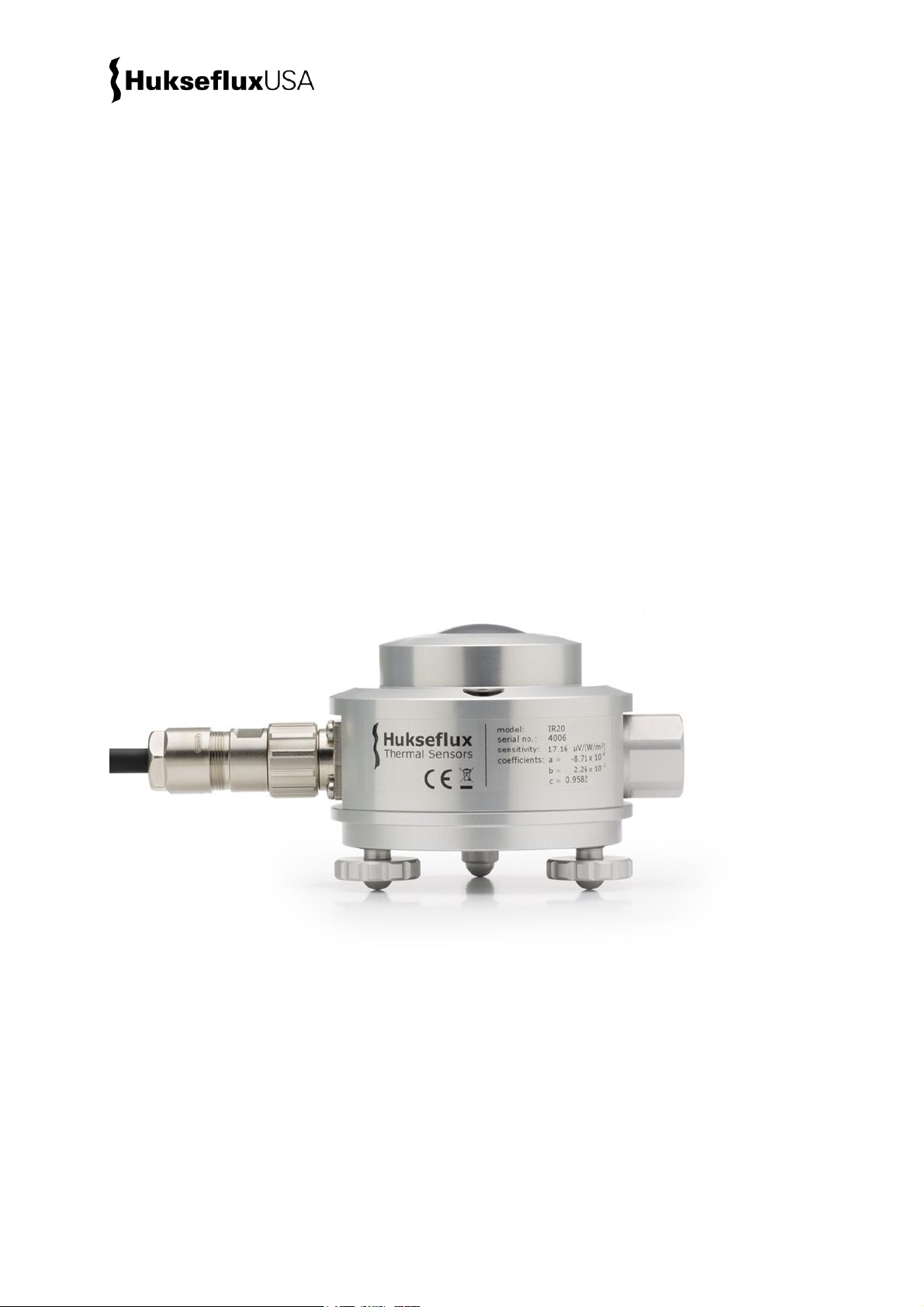
IR20 is a research grade pyrgeometer suitable for high-accuracy longwave irradiance
measurement in meteorological applications. IR20 is capable of measuring during both
day and night. In absence of solar radiation, model IR20WS offers even better accuracy
because of its wider spectral range.
IR20 measures the longwave or far-infra-red radiation received by a plane surface, in
W/m2, from a 180 ° field of view angle. In meteorological terms pyrgeometers are used
to measure “downward and upward longwave irradiance” (WMO definition). Longwave
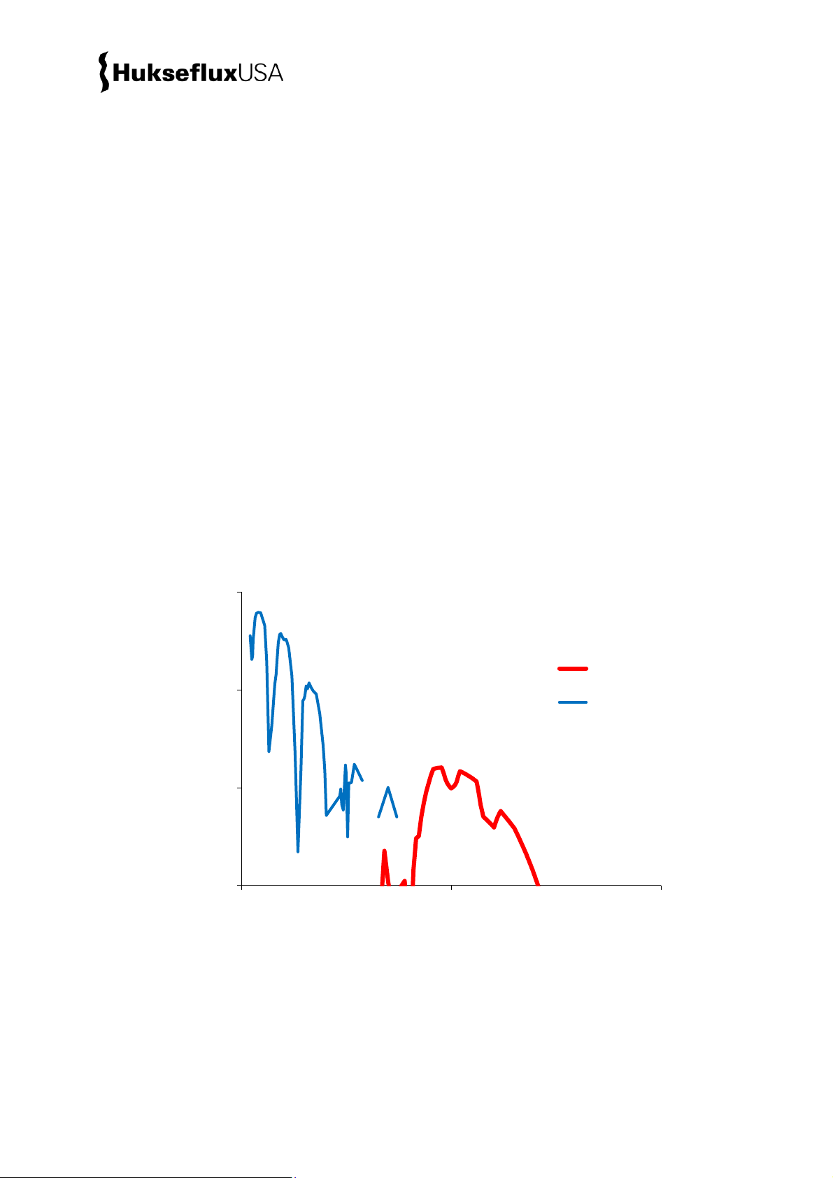
radiation is the part of radiation that is not emitted by the sun. The spectral range of
longwave radiation is not standardised. A practical cut-on is in the range of 4 to 5 x 10⁻⁶ m.
IR20 has a dome with a solar blind filter with a cut-on at 4.5 x 10⁻⁶ m, making it suitable
for day- and night observations.
Model IR20WS has a wide spectral range with a cut-on at 1.0 x 10⁻⁶ m. It offers a
superior accuracy during night-time, when solar radiation is absent.
The main purpose of a pyrgeometer is to measure longwave radiation. As secondary
measurands, the sky temperature Tsky, and the equivalent surface temperature Tsurface
can be measured. Both are so-called equivalent blackbody temperatures, i.e.
temperatures calculated from pyrgeometer data, assuming the source behaves as a
blackbody with an emission coefficient of 1.
Using IR20 is easy. It can be connected directly to commonly used data logging systems.
The irradiance in W/m2is calculated by dividing the IR20 output, a small voltage, by the
sensitivity and taking in account the irradiated heat by the sensor itself (Planck’s law).
The sensitivity is provided with IR20 on its calibration certificate. Please note that the
IR20 sensitivity is corrected for temperature dependence in the measurement equation
by using 3 additional constants. These coefficients are provided as well.
The central measurement equation governing IR20 is:
E = U/(S0·(a·T² + b·T + c)) + σ·(T + 273.15)4(Formula 0.1)
S = S0·(a·T² + b·T + c) (Formula 0.2)
The instrument should be used in accordance with the recommended practices of WMO.
Suggested use for IR20 and IR20WS:
climatological networks
extreme climates (polar / tropical)
moving platforms (aircraft, buoys)
uncertainty assessment (IR20 + IR20WS)
calibration reference (IR20WS)

IR20 manual v1604 6/39
Distinguishing features and benefits of IR20 are:
correction of temperature dependence by use of the measurement function. This is
far more accurate than temperature compensation in the instrument, especially at
very low and high temperatures. Every pyrgeometer is supplied with temperature
coefficients to enter into the equation.
high sensitivity. With sufficient input signal a typical datalogger no longer significantly
contributes to the uncertainty of the measurement.
low thermal-resistance of the sensor. Competing designs need a significant correction
for the difference in temperature between pyrgeometer body and sensor surface. For
IR20 this is not needed.
fast response time (3 s). A low response time is a benefit for measurements on
moving platforms such as aircraft and buoys.
on-board heater. Heating prevents condensation of water on the pyrgeometer dome
which, when occurring, leads to very large measurement errors.
instrument cut-on wavelength (5 %) and the two 50 % transmission points are
displayed on the product certificate for individual sensors.
Figure 0.1 IR20 research grade pyrgeometer with its sun screen removed
More about the instrument principle, theory and specifications can be found in the
following chapters.

IR20 manual v1604 7/39
Pyrgeometers are not subject to a classification standard.
Calibration of pyrgeometers is usually traceable to the World Infrared Standard Group
(WISG). This calibration takes into account the spectral properties of typical downward
longwave radiation. As an option, calibration can be made traceable to a blackbody and
the International Temperature Scale of 1990 (ITS-90). This alternative calibration is
appropriate for measurements of upward longwave radiation (IR20 facing down).
See the specific paragraph in this manual about calibration and uncertainty assessment
for more information.
This manual is intended for users of both IR20 and IR20WS. The specifications of
IR20WS are identical to IR20’s except for its spectral range.
Figure 0.1 IR20WS research grade pyrgeometer

IR20 manual v1604 8/39
1Ordering and checking at delivery
1.1 Ordering IR20
The standard configuration of IR20 is with 5 metres cable and a connector.
Common options are:
Longer cable (in multiples of 5 m). Specify total cable length.
Five silica gel bags in an air-thight bag for IR20 desiccant holder. Specify order
number DC01.
Optional calibration to blackbody (ITS-90).
IR20WS for the special wide spectrum model of IR20.
1.2 Included items
Arriving at the customer, the delivery should include:
pyrgeometer IR20 or IR20WS
cable of the length as ordered with connector
sun screen
product certificate matching the instrument serial number
calibration certificate matching the instrument serial number
temperature dependence report
any other options as ordered
Please store the certificates in a safe place.

IR20 manual v1604 9/39
1.3 Quick instrument check
A quick test of the instrument can be done by using a simple hand held multimeter and a
thermal source.
1. Check the electrical resistance of the sensor between the green (-) and white (+) wire.
Use a multimeter at the 1000 Ω range. Measure the sensor resistance first with one
polarity, than reverse the polarity. Take the average value. The typical resistance of the
wiring is 0.1 Ω/m. Typical resistance should be the typical sensor resistance of 300 to
500 Ω plus 1.5 Ω for the total resistance of two wires (back and forth) of each 5 m.
Infinite resistance indicates a broken circuit; zero or a low resistance indicates a short
circuit.
2. Check if the sensor reacts to heat: put the multimeter at its most sensitive range of
DC voltage measurement, typically the 100 x 10-3 VDC range or lower. Make sure that
the sensor is at 25 °C or lower. Expose the sensor to a heat source at a short distance
from the window of more than 50 °C, for instance a heavy (> 5 kg) painted block of
metal, or a painted metal container holding hot water. Face the side of the container to
avoid condensation of water on the pyrgeometer window. Stir the water to attain
homogeneity. A painted surface will act as a blackbody in the far-infra-red (FIR),
irrespective of the visible colour. The signal should read positive and > 1 x 10⁻³ V now. In
case of using your hand as a heat source, the signal should be significantly lower.
3. Remove the sun screen (see chapter on installation of the sun screen). Inspect the
bubble level.
4. Check the electrical resistance of the thermistor. This should be in the 104Ω range.
5. Check the electrical resistance of the heater. This should be in the 100 Ω range.
6. Inspect the instrument for any damage.
7. Inspect if the humidity indicator is blue. Blue indicates dryness. The colour pink
indicates it is humid: in the latter case replace the desiccant (see chapter on
maintenance).

IR20 manual v1604 10/39
2Instrument principle and theory
2.1 Pyrgeometer functionality
IR20’s scientific name is pyrgeometer. IR20 measures the longwave or far-infra-red (FIR)
radiation received by a plane surface, in W/m2, from a 180 ° field of view angle. In
meteorological terms pyrgeometers are used to measure “downward and upward
longwave irradiance” (WMO definition).
As secondary measurands, the sky temperature Tsky, and the equivalent surface (ground)
temperature Tsurface can be measured. Both are so-called equivalent blackbody radiative
temperatures, i.e. temperatures calculated from the pyrgeometer measurement
assuming these are uniform-temperature blackbodies with an emission coefficient of 1.
2.2 Solar and longwave radiation
Longwave radiation is the part of the radiation budget that is not emitted by the sun. The
spectral range of the longwave radiation is not standardised. A practical cut-on is in the
range of 4 to 5 x 10⁻⁶ m (see figure 2.2.1). In meteorology, solar- and longwave
radiation are typically measured as separate parameters. The instrument to measure
solar radiation is called pyranometer.
Figure 2.2.1 Atmospheric radiation as a function of wavelength plotted along two
logarithmic axes to highlight the longwave radiation. Longwave radiation is mainly
present in the 4 to 50 x 10-6 m range, whereas solar radiation is mainly present in the
0.3 to 3 x 10⁻⁶ m range. In practice, the two are measured separately using
pyrgeometers and pyranometers
0.001
0.010
0.100
1.000
110 100
spectral irradiance x 10-9 W/(m2/m)
wavelength x 10-6 m
downwelling
longwave
solar

IR20 manual v1604 11/39
In the longwave spectrum, the sky can be seen as a temperature source; colder than
ground level ambient air temperature, with its lowest temperatures at zenith, getting
warmer (closer to ambient air temperature) at the horizon. The uniformity of this
longwave source is much better than that in the range of the solar spectrum, where the
sun is a dominant contributor. The “equivalent blackbody” temperature, as a function of
zenith angle, roughly follows the same pattern independent of the exact sky condition
(cloudy or clear). This explains why for pyrgeometers the directional response is not very
critical.
The downwelling longwave radiation essentially consists of several components:
1. low temperature radiation from the universe, filtered by the atmosphere. The
atmosphere is transparent for this radiation in the so-called atmospheric window (roughly
the 10 to 15 x 10-6 m wavelength range).
2. higher temperature radiation emitted by atmospheric gasses and aerosols.
3. in presence of clouds or mist, the low temperature radiation from the universe is
almost completely blocked by the water droplets. The pyrgeometer then receives the
radiation emitted by the water droplets.
The spectral distribution of longwave irradiance varies significantly as a function of the
source composition. A pyrgeometer is relatively insensitive to these variations, but all the
same blackbody calibration tends to differ from WISG calibration by up to 5 %. In
addition there may be effects that are uncompensated for in the calibration (for instance
related to atmospheric water vapour content) in the 5 to 10 W/m2range. These effects
are still under investigation by the international scientific community. Comparison
between IR20 and IR20WS may serve to investigate this effect.
Upwelling longwave irradiance is measured with downfacing instruments. These are
presumably looking directly at the surface (absorption and emission of the atmosphere is
low over a short distance of around 2 m), which behaves like a normal blackbody.
Hukseflux suggests calibrating downfacing instruments against a blackbody rather than
having WISG as a reference.

IR20 manual v1604 12/39
2.3 IR20 pyrgeometer design
Figure 2.3.1Overview of IR20 pyrgeometer:
(1) cable (standard length 5 metres, optional longer cable)
(2) fixation of sun screen
(3) dome with solar blind filter
(4) sun screen
(5) humidity indicator
(6) desiccant holder
(7) levelling feet
(8) bubble level
(9) connector
By definition a pyrgeometer should not measure solar radiation, and in the longwave
have a spectral selectivity that is as “flat” as possible.
In an irradiance measurement by definition the response to “beam” radiation varies with
the cosine of the angle of incidence; i.e. it should have full response when the radiation
hits the sensor perpendicularly (normal to the surface, 0 ° angle of incidence), zero
response when the source is at the horizon (90 ° angle of incidence, 90 ° zenith angle),
and 50 % of full response at 60 ° angle of incidence.
A pyrgeometer should have a so-called “directional response” (older documents mention
“cosine response”) that is as close as possible to the ideal cosine characteristic.
1
2
3
4
5
6
7
8
9

IR20 manual v1604 13/39
In order to attain the proper directional and spectral characteristics, a pyrgeometer’s
main components are:
a thermal sensor with black coating. It has a flat spectrum covering the
0.3 to 50 x 10-6 m range, and has a near-perfect directional response. The coating
absorbs all longwave radiation and, at the moment of absorption, converts it to heat.
The heat flows through the sensor to the sensor body. The thermopile sensor
generates a voltage output signal that is proportional to the irradiance exchange
between sensor and source. The sensor not only absorbs, but also irradiates heat as a
blackbody.
a silicon dome. This dome limits the spectral range from 1.0 to 40 x 10-6 m (cutting
off the part below 1.0 x 10⁻⁶ m), while preserving the 180 ° field of view angle.
Another function of the dome is that it shields the thermopile sensor from the
environment (convection, rain).
a solar blind interference coating deposited on the dome (not for model IR20WS):
this coating limits the spectral range. It now becomes 4.5 to 40 x 10-6 m (cutting off
the part below 4.5 x 10⁻⁶ m).
Pyrgeometers can be manufactured to different specifications and with different levels of
verification and characterisation during production. Hukseflux also manufactures lower
accuracy pyrgeometers; see our pyrgeometer model IR02.
Model IR20 has a dome with a solar blind filter with a cut-on at 4.5 x 10⁻⁶ m, making it
suitable for day- and night observations.
Model IR20WS has a wide spectral range with a cut-on at 1.0 x 10⁻⁶ m. It offers a
superior accuracy under night-time conditions, when solar radiation is absent. See also
the appendix on uncertainty evaluation.

IR20 manual v1604 14/39
2.4 Typical measurement results
Please note that the signal generated by an upfacing pyrgeometer usually has a negative
sign. The most important factors determining downward longwave irradiance are:
ambient air temperature
sky condition / cloud cover
atmospheric moisture content
Table 2.4.1 Expected pyrgeometer output U/S at different ambient air temperatures,
Tambient , and at different cloud conditions. Under clear sky conditions the U/S is around
-100 W/m2while under cloudy conditions it will be close to 0 W/m2. Also calculated: the
sky temperature, Tsky, and the longwave downward irradiance E.
EXPECTED PYRGEOMETER OUTPUT CONDITIONS
Tambient
Sky condition
U/(S0·(a·T² + b·T + c))
Tsky
E
[°C]
[cloudy], [clear]
[W/m2]
[°C]
[W/m2]
-20
cloudy
0
-20
232
-20
clear sky
-100
-53
132
0
cloudy
0
+0
314
0
clear sky
-100
-24
214
+30
cloudy
0
+30
477
+30
clear sky
-100
+12
377
2.5 Optional heating
A low-power heater is located in the body of the pyrgeometer. The heater is not
necessarily switched on; recommended operation is to activate the heater when there is
a risk of dew deposition.
2.6 Optional shading
One of the larger errors in the daytime measurement of downwelling longwave irradiance
is the offset caused by solar radiation; the “solar offset”. Errors due to solar offset, are of
the order of + 10 W/m2at 1000 W/m2global horizontal irradiance. For ultra high
accuracy measurements this offset can be reduced by around 60 % by “shading”, which
means preventing the direct radiation to reach the instrument. Shading is typically done
by using a shading disk on a solar tracker.
2.7 Use as a net radiation sensor
Two pyrgeometers mounted back to back may be used to measure net longwave
radiation. Net longwave radiation is defined as downwelling minus upwelling longwave
irradiance. In case the two instruments are thermally coupled, the body temperatures of
the instruments are identical. In that case the body temperature cancels from the
equation for the net radiation. However for calculation of sky temperature and surface
temperature the instrument temperature still needs to be measured.

IR20 manual v1604 15/39
3Specifications of IR20 and IR20WS
3.1 Specifications of IR20 and IR20WS
IR20 research grade pyrgeometer measures the longwave irradiance received by a plane
surface, in W/m2, from a 180 ° field of view angle. In meteorological terms IR20
measures downward and upward longwave irradiance. Working completely passive, using
a thermopile sensor, IR20 generates a small output voltage proportional to the radiation
balance between the instrument and the source it faces. It can only be used in
combination with a suitable measurement system. The instrument is not subject to
classification. It should be used in accordance with the recommended practices of WMO.
IR20 measures during both day and night. In the absence of solar radiation IR20WS
offers a higher accuracy because of its wider spectral range. For ultra-high accuracy
measurements the user should consider to use the incorporated heater and should
consider “shading”the instrument during daytime.
Table 3.1.1 Specifications of IR20 and IR20WS (continued on next pages)
IR20 & IR20WS SPECIFICATIONS
MEASURANDS
Measurand
longwave radiation
Measurand in SI radiometry units
longwave irradiance in W/m2
Optional measurand
sky temperature
Optional measurand
surface temperature
IR20 VERSUS IR20WS: SPECTRAL RANGE & USE
Spectral range IR20
4.5 to 40 x 10-6 m
(nominal, see product certificate for individual value)
Spectral range IR20WS
1.0 to 50 x 10-6 m
(based on typical material properties only)
IR20WS restrictions for use
only in the absence of solar radiation
Solar offset
(IR20 only, not specified for IR20WS)
< 10 W/m2
(at 1000 W/m2global horizontal irradiance on the dome)
MAIN SPECIFICATIONS
Field of view angle
180 °
Response time (95 %)
3 s
Sensitivity (nominal)
17 x 10-6 V/(W/m2)
Sensitivity range
10 to 25 x 10-6 V/(W/m2)
Rated operating temperature range
-40 to +80 °C
Temperature dependence
< ± 0.4 % (-30 to +50 °C)
using the measurement function
Temperature sensor
10 kΩ thermistor
Required sensor power
zero (passive sensor)
Heater
12 VDC, 1.5 W
(see below for details)
Standard cable length
5 m

IR20 manual v1604 16/39
Table 3.1.1 Specifications of IR20 and IR20WS (continued)
ADDITIONAL SPECIFICATIONS
Zero offset b (response to 5 K/h change
in ambient temperature)
< ± 2 W/m2
Non-stability
< ± 1 % change per year
Non-linearity
< ± 0.5 % (100 to 300 W/m2, relative to 200 W/m2
sensor to source exchange)
Measurement range
-1000 to +1000 W/m2
(sensor to source exchange: U/(S0·(a·T² + b·T + c)) )
Tilt dependence
< ± 0.5 % (0 to 90 ° at 300 W/m2)
Sensor resistance range
300 to 500 Ω
Expected voltage output
Application for outdoor measurement of downward
longwave irradiance: -7.5 to 7.5 x 10⁻³ V
Measurement function / required
programming
E = U/(S0·(a·T² + b·T + c)) + σ·(T + 273.15)4
Measurement function / optional
programming for sky temperature
Tsky = (El↓/σ)1/4 - 273.15
Measurement function / optional
programming for surface temperature
Tsurface = (El↑/σ)1/4 - 273.15
Required readout
1 differential voltage channel or 1 single ended
voltage channel, input resistance > 106Ω
1 temperature channel
STANDARDS
Standard governing use of the
instrument
WMO-No. 8, Guide to Meteorological Instruments and
Methods of Observation, seventh edition 2008,
paragraph 7.4 "measurement of total and long-wave
radiation"
MOUNTING, CABLING, TRANSPORT
Chassis connector
M16 panel connector, male thread, 10-pole
Chassis connector type
HUMMEL AG 7.840.200.000 panel connector, front
mounting, short version
Cable connector
M16 straight connector, female thread, 10-pole
Cable connector type
HUMMEL AG 7.810.300.00M straight connector,
female thread, for cable diameter 3 to 6 x 10⁻³ m,
special version
Connector protection class
IP67 / IP69 K per EN 60 529 (connected)
Cable diameter
5.3 x 10⁻³ m
Cable replacement
replacement cables with connector can be ordered
separately from Hukseflux
Instrument mounting
2 x M5 bolt at 65 x 10-3 m centre-to-centre distance
on north-south axis, or 1 x M6 bolt at the centre of
the instrument, connection from below under the
bottom plate of the instrument
Levelling
bubble level and adjustable levelling feet are included
Levelling accuracy
< 0.1 ° bubble entirely in ring
Desiccant
two bags of silica gel, 0.5 g, 35 x 20 mm
Humidity indicator
blue when dry, pink when humid
IP protection class
IP67
Gross weight including 5 m cable
1.2 kg
Net weight including 5 m cable
0.85 kg
Packaging
box of 200 x 135 x 225 mm

IR20 manual v1604 17/39
Table 3.1.1 Specifications of IR20 and IR20WS (started on previous pages)
HEATING
Heater operation
the heater is not necessarily switched on;
recommended operation is to activate the heater
when there is a risk of dew deposition
Required heater power
1.5 W at 12 VDC
Heater resistance
95 Ω
Steady state zero offset caused by
heating
0 W/m2
CALIBRATION
Calibration traceability
to WISG
Optional traceability
to blackbody (ITS-90 )
Calibration hierarchy
from WISG through Hukseflux internal calibration
procedure involving outdoor comparision to a
reference pyrgeometer
Calibration method
outdoor comparison to a reference pyrgeometer
Calibration uncertainty
< 6 % (k = 2)
Recommended recalibration interval
2 years
Reference conditions
horizontal mounting, atmospheric longwave
irradiance, clear sky nights, 20 °C
Validity of calibration
based on experience the instrument sensitivity will not
change during storage. During use under exposure to
solar radiation the instrument “non-stability”
specification is applicable.
Hukseflux recommends ITS-90 traceable calibration
for upward longwave irradiance measurement.
Characterisation of the dependence of
sensitivity to temperature
temperature coefficients a, b and c of the
measurement equation are determined in an
independent experiment, and reported on the product
certificate
MEASUREMENT ACCURACY
Uncertainty of the measurement
statements about the overall measurement
uncertainty can only be made on an individual basis.
See the chapter on uncertainty evaluation
Achievable uncertainty (95 % confidence
level) daily totals
± 8 % (Hukseflux’own estimate)
VERSIONS / OPTIONS
Longer cable, in multiples of 5 m
option code = total cable length
Calibration
optional to blackbody (ITS-90 )
ACCESSORIES
Bags of silica gel for desiccant
set of 5 bags in an air tight bag
option code = DC01

IR20 manual v1604 18/39
3.2 Dimensions of IR20
Figure 3.2.1 Dimensions of IR20 and IR20WS in 10-3 m
68 Ø 150
M6M5 (2x)
65

IR20 manual v1604 19/39
4Standards and recommended practices
for use
Pyrgeometers are not subject to standardisation.
The World Meteorological Organization (WMO) is a specialised agency of the United
Nations. It is the UN system's authoritative voice on the state and behaviour of the
earth's atmosphere and climate. WMO publishes WMO-No. 8; Guide to Meteorological
Instruments and Methods of Observation, in which paragraph 7.4 covers "measurement
of total and long-wave radiation".
For ultra high accuracy measurements, the following manual may serve as a reference:
Baseline Surface Radiation Network (BSRN) Operations Manual, Version 2.1, L. J. B.
McArthur, April 2005, WCRP-121, WMO/TD-No. 1274.
This manual also includes chapters on installation and calibration.

IR20 manual v1604 20/39
4.1 Site selection and installation
Table 4.1.1 Recommendations for installation of pyrgeometers
Location
the horizon should be as free from obstacles as
possible. Ideally there should be sources of longwave
irradiance between the course of the sun and the
instrument, only free sky.
Mechanical mounting / thermal insulation
preferably use connection by bolts to the bottom plate
of the instrument. A pyrgeometer is sensitive to
thermal shocks. Do not mount the instrument with the
body in direct thermal contact to the mounting plate
(so always use the levelling feet also if the mounting
is not horizontal), do not mount the instrument on
objects that become very hot (black coated metal
plates).
Instrument mounting with 2 bolts
2 x M5 bolt at 65 x 10-3 m centre to centre distance
on north-south axis, connection from below under the
bottom plate of the instrument.
Instrument mounting with one bolt
1 x M6 bolt at the centre of the instrument,
connection from below under the bottom plate of the
instrument.
Performing a representative
measurement
the pyrgeometer measures the solar radiation in the
plane of the sensor. This may require installation in a
tilted or inverted position. The sensor surface (sensor
bottom plate) should be mounted parallel to the plane
of interest.
In case a pyrgeometer is not mounted horizontally or
in case the horizon is obstructed, the
representativeness of the location becomes an
important element of the measurement. See the
chapter on uncertainty evaluation.
Levelling
in case of horizontal mounting only use the bubble
level and levelling feet. For inspection of the bubble
level the sun screen must be removed.
Instrument orientation
by convention with the cable exit pointing to the
nearest pole (so the cable exit should point north in
the northern hemisphere, south in the southern
hemisphere).
Installation height
in case of inverted installation, WMO recommends a
distance of 1.5 m between soil surface and sensor
(reducing the effect of shadows and in order to obtain
good spatial averaging).
Optional shading
for ultra-high accuracy measurements the solar offset
can be reduced by around 60 % by “shading”, which
means preventing the direct radiation to reach the
instrument. Shading is typically done by using a
shading disk on a solar tracker.
This manual suits for next models
1
Table of contents
Other Hukseflux Measuring Instrument manuals

Hukseflux
Hukseflux SR20 User manual

Hukseflux
Hukseflux TRSYS20 User manual

Hukseflux
Hukseflux NR01 User manual

Hukseflux
Hukseflux SR05 series User manual

Hukseflux
Hukseflux DR01 User manual

Hukseflux
Hukseflux SR25-D2 User manual

Hukseflux
Hukseflux FTN02 User manual

Hukseflux
Hukseflux TPSYS20 User manual

Hukseflux
Hukseflux SR20-D2 User manual

Hukseflux
Hukseflux SR30-D1 User manual