8 Version 06/12 Instruction Manual UNIVERSAL
3 Intended use
The UNIVERSAL vehicle transporter is designed to be
attached to a permissible towing vehicle. It may be loaded
within the permissible total weight.
The transport of dangerous goods, e.g. chemical substances,
is not permitted. It must be possible to distribute the weight
of the load evenly through the load. When loading the trai-
ler with a single load, this must allow an even weight distri-
bution. The centre of gravity of the load must be in front of
the axles. The permissible drawbar load must be observed.
The driver of the towing vehicle is responsible for securing
the load or equipment for securing the load. The driver must
observe the respective country-specic laws and standards
for load securing.
The trailer may only be operated in technically perfect
condition.
4 Use contrary to intended purpose
For all types of the UNIVERSAL vehicle transporter, the fol-
lowing shall be deemed to be improper use:
• Loaded with a too high payload.
• Transporting people with the trailer.
• Driving with an unsecured load.
• Exceeding the drawbar load and the trailer load
• Unauthorised structural modications to the trailer.
• Transport of hot materials (e.g. tar).
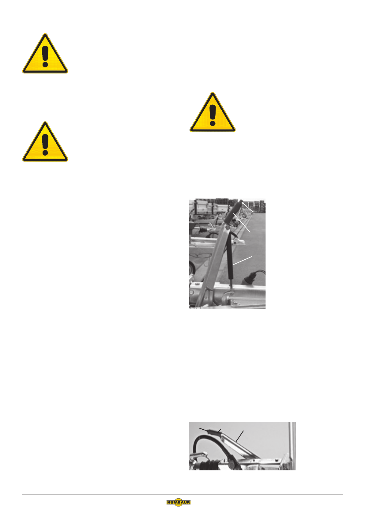
5General safety instructions
Danger of life!
Driving with incorrectly raised support
wheel.
The support wheel blocks the brake
system. The brakes do not react and the
trailer is completely unbraked in critical
situations. In resulting accidents, people
can be injured, killed or objects dama-
ged.
Crank thes support wheel for travel
completely and up so that nothing can
block the support wheel.
Danger of life!
Driving with an unsecured load..
The load or parts of the load can be
thrown out and hit people. This can lead
to injuries or even death.
Secure the load every time you drive.
Danger!
Danger!
Danger of life!
Driving without the jockey wheel fully
cranked up and in the upright position..
The support wheel can break o and be
thrown away and hit people. This can
lead to injuries or even death.
Ensure that the jockey wheel is fully raised and cranked up
for travel
Danger of life!
Driving with incorrect load distribution.
The trailer can skid and break o or cau-
se the towing vehicle to skid as well. This
can injure or kill people and damage
property.
Distribute the load for the journey in
accordance with the applicable laws and
regulations.
Danger of life!
Driving at excessive speed.
The trailer may skid and break o or
cause the towing vehicle to skid as well.
This can injure or kill people or damage
property.
The applicable laws of the respective
country for the maximum permissible
speed when driving as a trailer combina-
tion must be observed.
Danger of life!
Driving with the drive-up ramps suspen-
ded.
The drive-up ramps can be lost while
driving. In the event of an accident,
persons may be injured, killed or objects
damaged.
Stow the drive-up ramps in the ramp
compartment before driving of.
Danger!
Danger!
Danger!