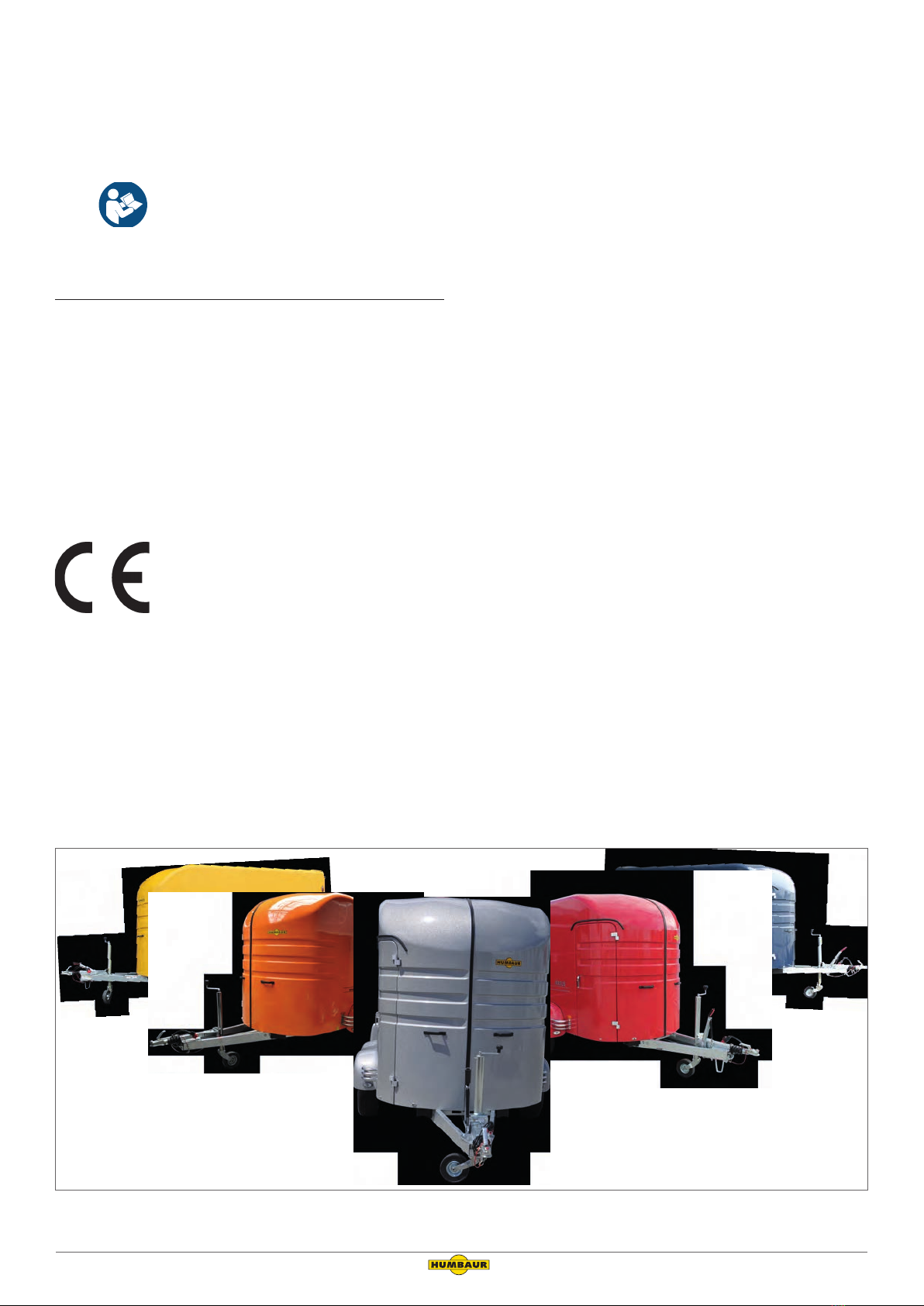
REXUS operating instruction manual (Part 2) Version 2019/01 9
5 General Safety Instructions
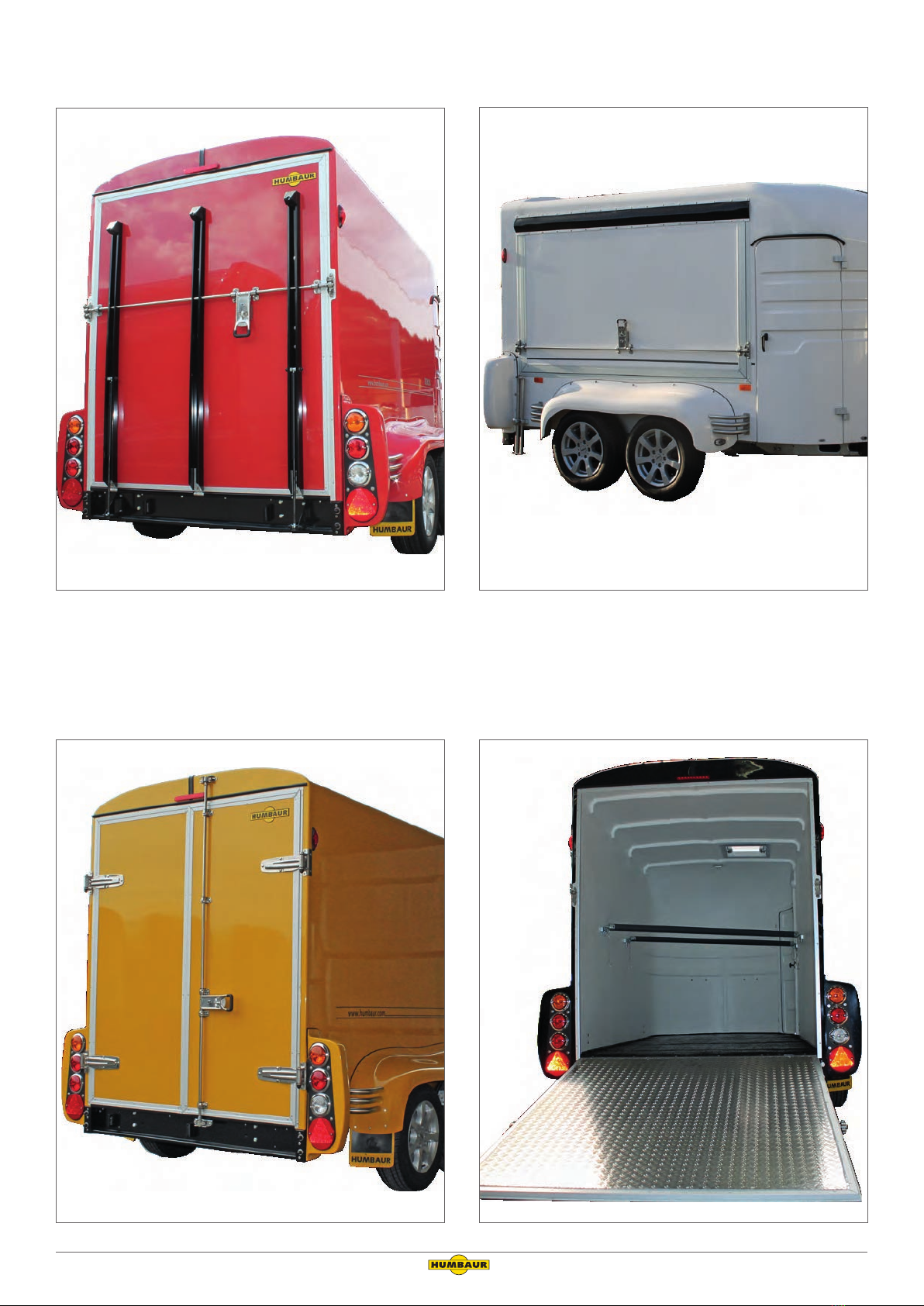
Folding ramp wall!
After unlocking, the ramp wall can fall down
uncontrollably, e.g. from load pressure - risk of
collision!
This can result in feet being crushed.
►►Stand to the side when unlocking the ramp wall.
►►Relieve the load pressure beforehand, if necessary.
►►Allow the ramp wall to fall to the floor if the gas struts
are defective.
Never try to stop it.
►►Keep your feet away from the area round the
ramp wall.
►►Keep people away from the area around
the ramp wall during unfolding.
►►Use .
Swivelling double wing doors!
After unlocking, the double wing doors can swiv-
el uncontrollably, e.g. by load pressure / gust of
wind - risk of collision!
►►Keep yourself and other people clear of the swivel area.
►►Unlock the double wing doors carefully and press against
them, if necessary.
►►Relieve the load pressure beforehand, if necessary.
Swivelling sales hatch!
After unlocking, the sales hatch can swivel up
uncontrollably - risk of collision!
►►Keep yourself and other people clear of the swivel area.
Observe the other general safety recommendations in
the operating instruction manual "Trailers up to 3.5"
(General Points - Part 1).
6 Loading and Unloading
6.1 Load distribution
Before loading, check the max. load capacity that you
are able to transport with your trailer.
Check that the max. permissible body dimensions of
your trailer are not exceeded.
The load distribution works directly on the road handling of the
towing vehicle tension.
NOTICE
Poor / one-sided load distribution of the goods!
Strongly uneven / point load distribution can lead to over-
stresssing and damage to the trailer components.
►►Before loading your trailer, check which load objects are
the heaviest.
►►Position the heaviest objects centrally on the cargo bed
and in the area of the axles.
►►Distribute the goods evenly over the cargo bed
- Avoid point / one-sided load distribution.
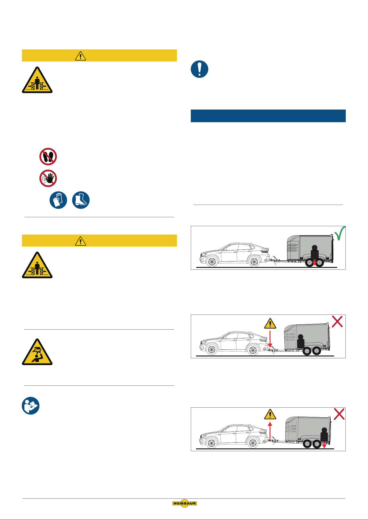
Correct load distribution
Load in axle region
The trailer and the towing vehicle are stable with all wheels on
the ground.
Incorrect load distribution
Load too far forward (to motor vehicle)
The trailer tilts forwards; the towing vehicle tilts backwards =
the max. drawbar load has been exceeded.
Incorrect load distribution
Load too far backwards (to motor vehicle)
The trailer tilts backwards; the towing vehicle tilts forwards =
the drawbar load is too low or negative.