Humless UL 9540 User manual

Version: 1.2 November 2022 © Humless 2022
www.humless.com Page 2
Table Of Contents
Chapter
Description
Page
1.
Introduction ………………………………………………………………………………..………
4
2.
Important Safety Information …………………………………………………………………….
5
3.
Unpacking & Overview …………………………………………………………………………...
7
3.1
Packing List ………………………………………………………………………………………..
7
3.2
Product Overview …………………………………………………………………………………
7
4.
Installation …………………………………………………………………………………………
8
4.1
Precautions ………………………………………………………………………………………..
8
4.2
Selecting Mounting Location …………………………………………………………………….
8
4.3
Mounting the Unit …………………………………………………………………………………
8
5.
Grid (Utility) Connection ………………………………………………………………………….
9
5.1
Preparation ………………………………………………………………………………………...
9
5.2
Connecting to the AC Utility ……………………………………………………………………..
10
6.
Generator connection …………………………………………………………………………….
10
6.1
Preparation ………………………………………………………………………………………...
11
6.2
Connecting to the Generator Input ……………………………………………………………...
11
7.
PV Module (DC) Connection …………………………………………………………………….
12
8.
Battery Connection ……………………………………………………………………………….
15
9.
Load (AC Output) Connection …………………………………………………………………...
16
9.1
Preparation ………………………………………………………………………………………...
16
9.2
Connecting the AC Output ……………………………………………………………………….
17
10.
Communication ……………………………………………………………………………………
18
10.1
Pin Assignment for RS-232 Communication Port ……………………………………………..
19
10.2
Pin Assignment for BMS Communication Port ………………………………………………...
19
10.3
Dry Contact Signal ……………………………………………………………………………….
19
11.
Commissioning ……………………………………………………………………………………
21
12.
Initial Setup ………………………………………………………………………………………..
22

Version: 1.2 November 2022 © Humless 2022
www.humless.com Page 3
13.
Operation …………………………………………………………………………………………..
33
13.1
Interface ……………………………………………………………………………………………
33
13.2
Touch screen Information ….…………………………………………………………………….
33
13.3
Touch Screen Function Keys ………………………………………………………………….
34
13.4
LCD Settings ………………………………………………………………………………………
36
13.5
Query Menu Operation …………………………………………………………………………...
44
13.6
Operation Mode & Display ……………………………………………………………………….
50
14.
Charging Management …………………………………………………………………………...
55
15.
Maintenance & Cleaning ………………………………………………………………………...
57
16.
Trouble Shooting ………………………………………………………………………………….
58
16.1
Warnings …..……………………………………………………………………………………….
58
16.2
Fault reference Codes ……………………………………………………………………………
59
17.
Specifications ……………………………………………………………………………………...
60
Appendix I: Parallel Installation Guide ………………………………………………………….
62
Appendix II: Wi-Fi Operation Guide …………………………………………………………….
69

Version: 1.2 November 2022 © Humless 2022
www.humless.com Page 4
1. Introduction
This hybrid PV Inverter can provide power to connected loads by utilizing PV power, utility power, and battery power.
Hybrid Inverter
Depending on different power situations, this hybrid Inverter is designed to generate continuous power from PV solar
modules (solar panels), batteries, and the utility. When MPP input voltage of PV modules are within an acceptable
range (see specification for the details), this Inverter is able to generate power to feed the Grid (utility) and charge the
battery. This Inverter is only compatible with PV module types of single crystalline and polycrystalline. Do not connect
any PV array types other than these two types of PV modules to the Inverter. Do not connect the positive or negative
terminal of the solar panel to the ground. See Figure 1 for a simple diagram of a typical solar system with this hybrid
Inverter.

Version: 1.2 November 2022 © Humless 2022
www.humless.com Page 8
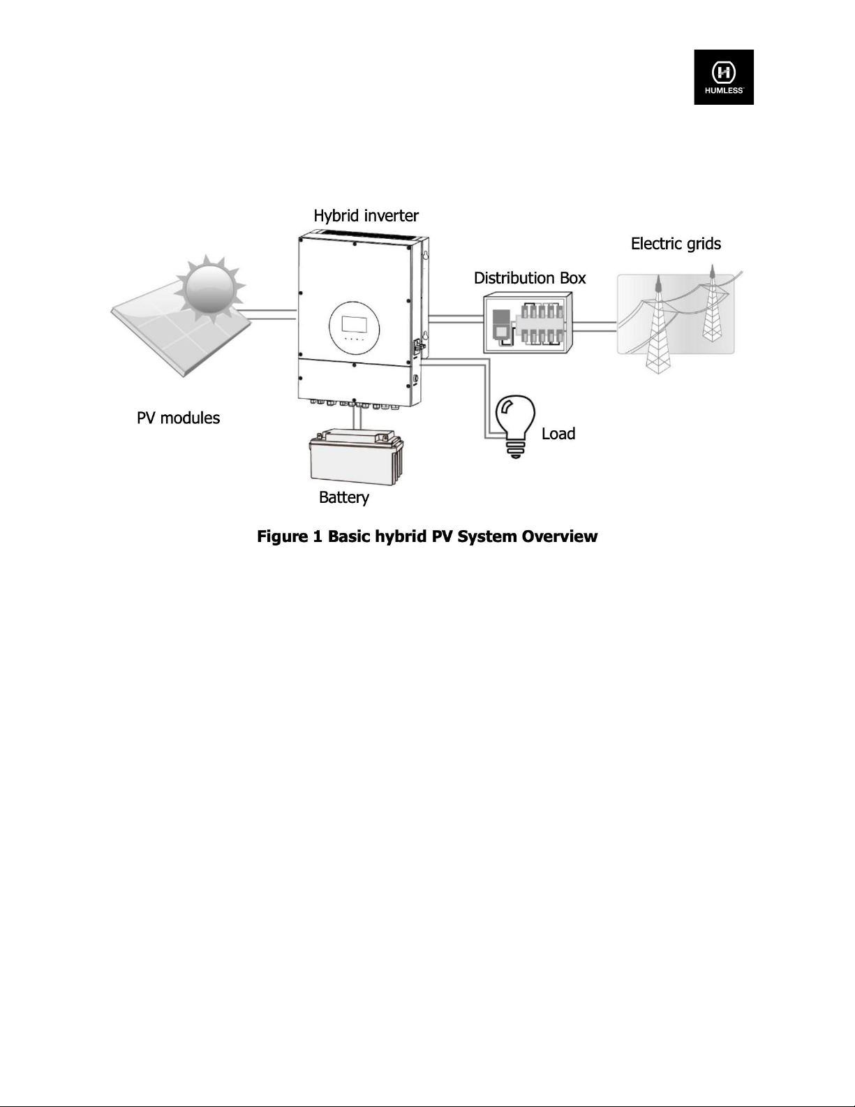
4. Installation
4.1. Precautions
This hybrid Inverter is designed for indoor or outdoor use (IP65), please make sure the installation site meets the below
conditions:
●Do not install in direct sunlight.
●Do not install near flammable liquids.
●Do not install near explosive materials.
●Do not install in a windy or drafty area.
●Do not install where there is the possibility of contact with snow.
●Do not install near an antenna or antenna cable.
●Do not install more than 6500ft (2000m) above sea level.
●Do not install in an area exposed to the elements.
●Do not install in an area with a humidity greater than 95%.
4.2. Selecting Mounting Location
●Select a vertical wall with the appropriate load-bearing capacity, it should also be non-flammable.
●The ambient temperature should be between 77F - 140F (25C-60C) in order to ensure optimal operation.
●Ensure that there is sufficient clearance between components as illustrated in order to ensure sufficient heat
dissipation and adequate access to wiring. Clearances should be 20 inches (50cm) on the top, bottom, and
sides and 40 inches (100cm) to the front.
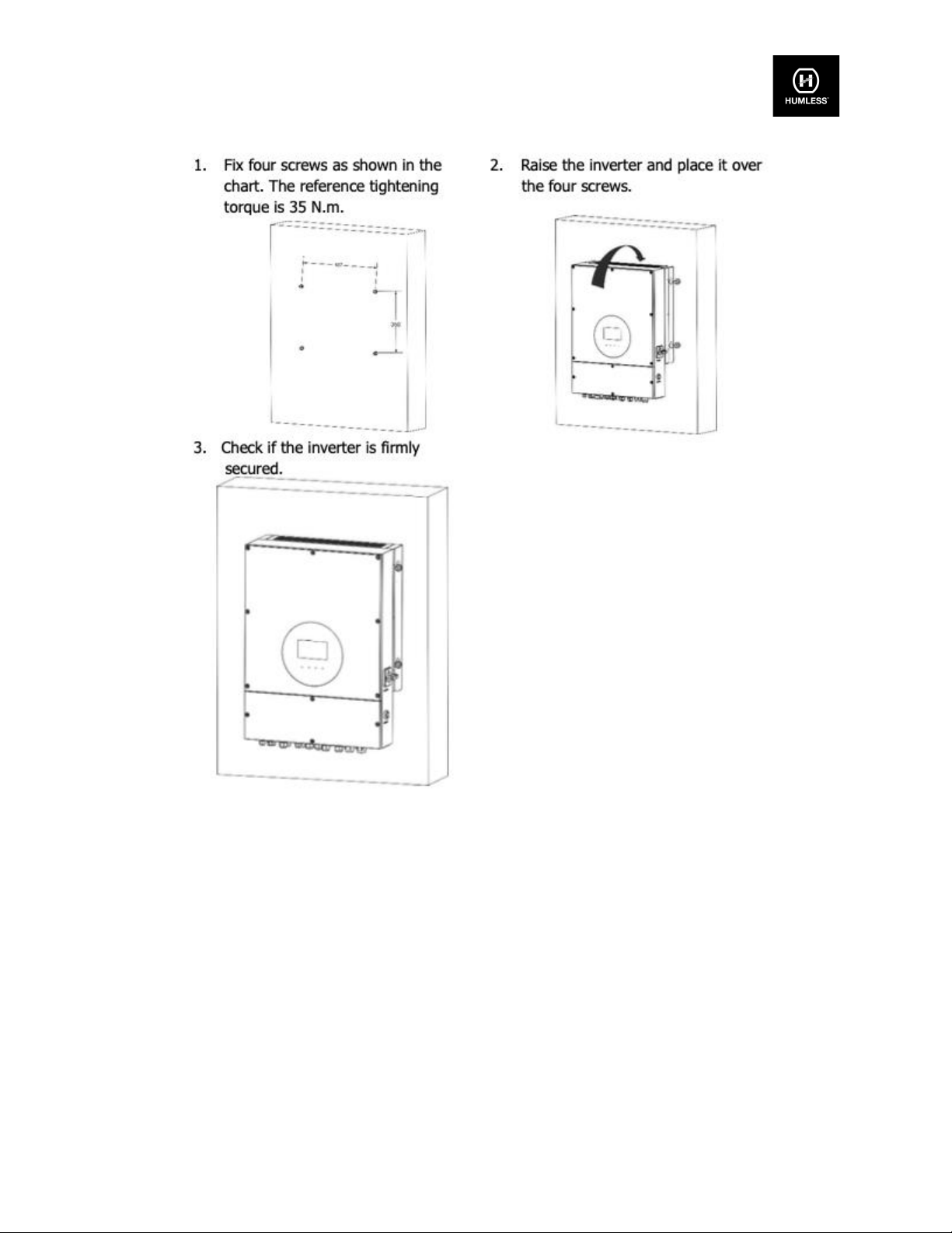
4.3. Mounting the Unit

Version: 1.2 November 2022 © Humless 2022
www.humless.com Page 9
5. Grid (Utility) Connection
5-1. Preparation
NOTE 1: The overvoltage category of the AC input is III. It should be connected to the power distribution.
NOTE 2: Before connecting to the Grid, please install a separate AC breaker between the Inverter and the Grid. This
will ensure the Inverter can be safely disconnected during maintenance and fully protected from overcurrent. The
recommended size of the AC breaker is 40A/300V.
WARNING! It is extremely important for system safety and efficient operation to use the appropriate cable for the Grid
(utility) connection. To reduce the risk of injury, please use the proper recommended cable size as below.

Version: 1.2 November 2022 © Humless 2022
www.humless.com Page 10
Suggested cable requirement for AC wire
Nominal Grid Voltage
120VAC per phase
Conductor cross-section (mm2)
10 - 16
AWG no.
8 - 6
5-2. Connecting to the AC Utility
Please follow the below steps to implement an AC input connection:
1. Before making an AC input connection, be sure to open the DC protector or disconnector first.
2. Remove the insulation sleeve 7mm for four conductors.
3. Insert AC input wires accordingto the polarities indicated onthe terminal block and tightenthe terminal screws.
6. Generator Connection
There are two functions with this port:
●One allows generator input as power source
●The other allows second AC output to connect. This output can be turned On or Off by setting
the battery voltage.

Version: 1.2 November 2022 © Humless 2022
www.humless.com Page 11
6.1 Preparation
NOTE 1: The overvoltage category of the AC input is III. It should be connected to the power distribution.
NOTE 2: Before connecting to the Grid, please install a separate AC breaker between the Inverter and the Grid. This
will ensure the Inverter can be securely disconnected during maintenance and fully protected from overcurrent. The
recommended size of AC breaker is 40A/300V.
WARNING! It is extremely important for system safety and efficient operation to use the appropriate cables for the
generator connection. To reduce the risk of injury, please use the proper recommended cable size as below.
Suggested cable requirement
Nominal Grid Voltage
120VAC per phase
Conductor cross-section (mm2)
10 - 16
AWG no.
8 - 6
6.2 Connecting to the Generator Input
Please follow the below steps to implement generator input connection:
1. Before making the generator input connection, be sure to open DC protector or disconnector first.
2. Remove the insulation sleeve 7mm for four conductors.
3. Insert input wires according to the polarities indicated on the terminal block and tighten the terminal screws.

Version: 1.2 November 2022 © Humless 2022
www.humless.com Page 12
7. PV Module (DC) Connection
CAUTION: Before connecting to PV modules, please install separately a DC circuit breaker between the Inverter
and PV modules.
NOTE1: Please use 1000VDC/20A circuit breaker.
NOTE2: The overvoltage category of the PV input is II.
Please follow the below steps to implement PV module connection:
Step 1: Check the input voltage of PV arraymodules. The acceptable input voltage of the Inverter is 120VDC - 600VDC.
This system is applied with two strings of PV array. Please make sure that the maximum current load of each PV input
connector is 15A.
Step 2: Disconnect the circuit breaker and switch off the DC switch.
Step 3: Remove the insulation sleeve 7 mm for positive and negative conductors.
Step 4: Check the correct polarity of the connection cable from PV modules and PV input connectors. Then, connect
the positive pole (+) of the connection cable to the positive pole (+) of the PV input connector. Connect the negative
pole (-) of the connection cable to the negative pole (-) of the PV input connector.
CAUTION: Exceeding the maximum input voltage can destroy the unit!! Check the system before connecting.

Version: 1.2 November 2022 © Humless 2022
www.humless.com Page 15
8. Battery Connection
CAUTION: Before connecting to batteries, please install a separate DC circuit breaker between the Inverter and
batteries.
NOTE1: Only Humless LiFePO4 batteries can be connected to this Inverter (see www.humless.com).
NOTE2: Please use 60VDC/200A circuit breaker.
NOTE3: The overvoltage category of the battery input is II.
The following steps are required in order to connect the battery:
Step 1: Check the nominal voltage of the batteries. The nominal input voltage for the Inverter is 48VDC.
Step 2: Use two battery cables. Remove the insulation sleeve 10 mm and insert the conductor into the cable ring
terminal.
WARNING: Be sure the length of all battery cables is the same. Otherwise, there will be a voltage difference between
the Inverter and battery causing parallel Inverters not to work.
Step 3: Insert battery wires according to the polarities indicated on the terminal block and tighten the terminal screws.
Make sure the polarity at both the battery and the Inverter/charge is correctly connected.

Version: 1.2 November 2022 © Humless 2022
www.humless.com Page 16
WARNING! Incorrect connections will damage the unit permanently.
Step 4: Make sure the wires are securely connected. The reference tightening torque is
5.5~7.0 N.m.
9. Load (AC Output) Connection
9.1 Preparation
CAUTION: To prevent further supply to the load via the Inverter during any mode of operation, an additional
disconnection device should be placed in the building wiring installation.
WARNING! It's very important for system safety and efficient operation to use appropriate cable for AC connection. To
reduce the risk of injury, please use the proper recommended cable size as below.
9.2 Connecting to the AC output

Version: 1.2 November 2022 © Humless 2022
www.humless.com Page 17
Step 1: Before making the output connection, be sure to open the DC protector or disconnector first.
Step 2: Remove the insulation sleeve 7mm for four conductors.
Step 3: Insert AC input wires according to the polarities indicated on the terminal block and tighten the terminal screws.

Version: 1.2 November 2022 © Humless 2022
www.humless.com Page 18
10. Communication
The Inverter is equipped with several communication ports, and it is also equipped with a slot for alternative
communication interfaces in order to communicate with a PC with corresponding software. Follow the below procedure
to connect communication wiring and install the software. Install the monitoring software on your computer. Detailed
information is listed in the next chapter. Once the software is installed, you may initiate the monitoring module and read
data through the communication port.
Wi-Fi Connection
This unit is equipped with a Wi-Fi transmitter. Wi-Fi transmitters can enable wireless communication between off-Grid
Inverters and the monitoring platform. Users can access and control the monitored Inverter with the downloaded APP.
you can download the “SolarPower Wi-Fi” app from the Apple Store® or “SolarPower” on the Google Play® Store. All
dataloggers and parameters are saved in iCloud. For quick installation and operation, please refer to Appendix II -
See the Wi-Fi Operation Guide for details.

Version: 1.2 November 2022 © Humless 2022
www.humless.com Page 19
10.1 Pin Assignment for RS-232 Communication Port
10.2 Pin Assignment for BMS Communication Port
10.3 Dry Contact Signal
There is one dry contact available on the bottom panel, this can be used to control the external generator.
Electrical Parameters
Note: The application of the dry contact should not exceed the electric parameter shown above as this will damage
the internal relay.
This manual suits for next models
2
Table of contents
Other Humless Inverter manuals
Popular Inverter manuals by other brands

Delta
Delta M30A 230 Operation and installation manual

Go Power
Go Power GP-12-300 instruction manual

FRONIUS
FRONIUS Rapid Shutdown Box Duo operating instructions

Tripp Lite
Tripp Lite PowerVerter Plus DC-to-AC Inve owner's manual

FRONIUS
FRONIUS Primo 208-240 3.8-1 Installation instruction

FRONIUS
FRONIUS Tauro 50-3-D quick start guide