manuals.online logo
Brands
  1. Home
  2. •
  3. Brands
  4. •
  5. Hunter
  6. •
  7. Fan
  8. •
  9. Hunter MD520-01 User manual

Hunter MD520-01 User manual

Other Hunter Fan manuals
Hunter DDI User manual

Hunter

Hunter DDI User manual

Hunter 22710 Instruction Manual

Hunter

Hunter 22710 Instruction Manual

Hunter Advocate 59368 User manual

Hunter

Hunter Advocate 59368 User manual

Hunter 82022 User manual

Hunter

Hunter 82022 User manual

Hunter 20531 Manual

Hunter

Hunter 20531 Manual

Hunter Ernest Hemingway Series User manual

Hunter

Hunter Ernest Hemingway Series User manual

Hunter Tunley User manual

Hunter

Hunter Tunley User manual

Hunter Georgetown User manual

Hunter

Hunter Georgetown User manual

Hunter Heathrow Instruction manual

Hunter

Hunter Heathrow Instruction manual

Hunter Minimus 51431 User manual

Hunter

Hunter Minimus 51431 User manual

Hunter 22720 Manual

Hunter

Hunter 22720 Manual

Hunter Captiva 21318 Instruction Manual

Hunter

Hunter Captiva 21318 Instruction Manual

Hunter Fairhaven 53031 Instruction manual

Hunter

Hunter Fairhaven 53031 Instruction manual

Hunter Heritage 90302 Instruction manual

Hunter

Hunter Heritage 90302 Instruction manual

Hunter Type 2 Series Service manual

Hunter

Hunter Type 2 Series Service manual

Hunter 41457-01 User manual

Hunter

Hunter 41457-01 User manual

Hunter 41225-01 Instruction manual

Hunter

Hunter 41225-01 Instruction manual

Hunter 23277 User manual

Hunter

Hunter 23277 User manual

Hunter 20775 Manual

Hunter

Hunter 20775 Manual

Hunter 42606-01 User manual

Hunter

Hunter 42606-01 User manual

Hunter 20517 Manual

Hunter

Hunter 20517 Manual

Hunter 53151 Instruction manual

Hunter

Hunter 53151 Instruction manual

Hunter 23970 Instruction Manual

Hunter

Hunter 23970 Instruction Manual

Hunter Stanley Park 50585 User manual

Hunter

Hunter Stanley Park 50585 User manual

Popular Fan manuals by other brands

Minka Group minkaAire Wave F843 instruction manual

Minka Group

Minka Group minkaAire Wave F843 instruction manual

Airflow Adroit DV50 instruction manual

Airflow

Airflow Adroit DV50 instruction manual

Vornado 270 Series owner's guide

Vornado

Vornado 270 Series owner's guide

comfort air TH-10D instruction manual

comfort air

comfort air TH-10D instruction manual

Livoo DOM386 instruction manual

Livoo

Livoo DOM386 instruction manual

Holmes BLIZZARD HAOF-90 owner's guide

Holmes

Holmes BLIZZARD HAOF-90 owner's guide

Taurus GRECO 16 ELEGANCE manual

Taurus

Taurus GRECO 16 ELEGANCE manual

Quorum PINNACLE installation instructions

Quorum

Quorum PINNACLE installation instructions

Monte Carlo Fan Company 3DIR58RBD-V1 Owner's guide and installation manual

Monte Carlo Fan Company

Monte Carlo Fan Company 3DIR58RBD-V1 Owner's guide and installation manual

Craftmade UH52 installation guide

Craftmade

Craftmade UH52 installation guide

Jocel JVA030658 instruction manual

Jocel

Jocel JVA030658 instruction manual

MIKA MFB1211/GR user manual

MIKA

MIKA MFB1211/GR user manual

Harbor Breeze RLG52NWZ5L manual

Harbor Breeze

Harbor Breeze RLG52NWZ5L manual

Allen + Roth L1405 instruction manual

Allen + Roth

Allen + Roth L1405 instruction manual

ViM KUBAIR F400 ECOWATT Technical manual

ViM

ViM KUBAIR F400 ECOWATT Technical manual

HIDRIA R10R-56LPS-ES50B-04C10 user guide

HIDRIA

HIDRIA R10R-56LPS-ES50B-04C10 user guide

BLAUBERG Ventilatoren CENTRO-M 100 L user manual

BLAUBERG Ventilatoren

BLAUBERG Ventilatoren CENTRO-M 100 L user manual

Triangle Engineering HEAT BUSTER SPL Series owner's manual

Triangle Engineering

Triangle Engineering HEAT BUSTER SPL Series owner's manual

manuals.online logo
manuals.online logoBrands
  • About & Mission
  • Contact us
  • Privacy Policy
  • Terms and Conditions

Copyright 2025 Manuals.Online. All Rights Reserved.

www.ventiladoreshunter.com.br
MD520-01 • 10/06/14 • © Hunter Fan Company
ENGLISH
Important Instructions: Keep Instructions for future use
1
www.hunterfan.com.br
MD520-01 • 10/06/14 • © Hunter Fan Company
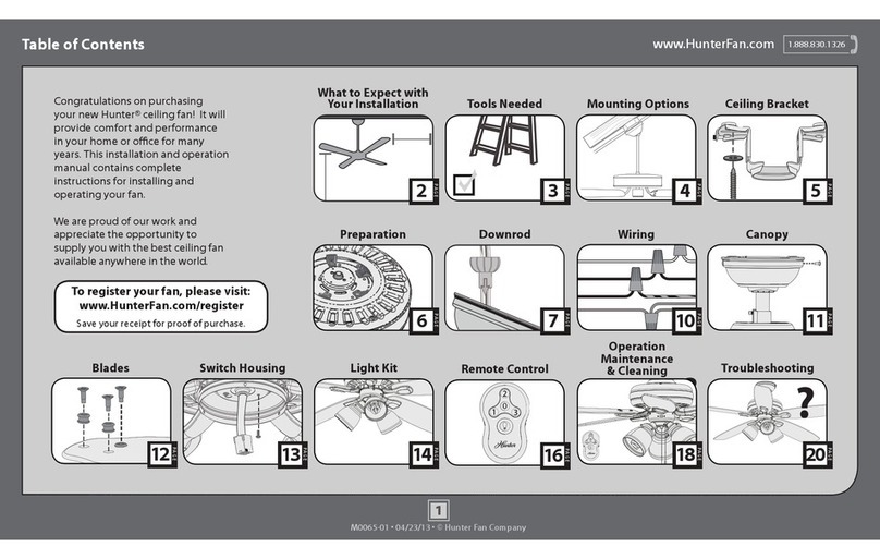
Table of Contents
PAG E
17
Warranty Statement
Congratulations on purchasing your new Hunter®
ceiling fan! It will provide comfort and performance
in your home or ofce for many years. This installation
and operation manual contains complete instructions
for installing and operating your fan.
We are proud of our work and appreciate the
opportunity to supply you with the best ceiling fan
available anywhere in the world.
PAG E
6
Downrod
PAG E
10
BladesCanopy
PAG E
9
PAG E
8
Wiring
Operation, Maintenance,
& Cleaning
Light Kit
PAG E
11
PAG E
15
Wall Control
PAG E
13
Troubleshooting
?
PAG E
16
?
?
PAG E
5
Ceiling BracketMounting Options
PAG E
4
Ladder
PAG E
3
Tools Needed
30 inches
7 feet
PAG E
2
What to Expect with
Your Installation
www.hunterfan.com.br
2
MD520-01 • 10/06/14 • © Hunter Fan Company
What to Expect with Your Installation
w.1 - To reduce the risk of re, electrical shock, or personal injury,
mount fan directly from building structure and/or an outlet
box marked acceptable for fan support of 31.8 kg and use the
mounting screws provided with the outlet box.
w.2 - To avoid possible electrical shock, before installing or
servicing your fan, disconnect the power by turning off the circuit
breakers to the outlet box and associated wall switch location. If
you cannot lock the circuit breakers in the off position, securely
fasten a prominent warning device, such as a tag, to the service
panel.
w.3 - To reduce the risk of re, electrical shock, or motor damage,
use only Hunter Solid State Speed Controls.
w.4 - To reduce the risk of personal injury, do not bend the blade
brackets when installing the blade brackets, balancing the blades, or
cleaning the fan. Do not insert foreign objects in between rotating fan
blades.
w.5 - This appliance is not intended for use by persons (including
children) with reduced physical, sensory or mental capabilities, or
people with a lack of experience and knowledge, unless they have
received instructions regarding the use of the device or under the
supervision of a person responsible for their safety.
w.6 - It is recommended that children be supervised to ensure that
they are not using the appliance improperly
c.1 - All wiring must be in accordance with national and local
electrical codes. If you are unfamiliar with wiring, use a qualied
electrician.
c.2 - Use only Hunter replacement parts.
You may need a
friend to help you.
Check box to see
fan weight
Assess location
0,50 meters
from blade tip to
nearest wall or
obstruction 2,3 meters
from bottom
edge of blade to
the oor
Know your wiring
If you are unfamiliar
with wiring, use a
qualied electrician.
WARNINGS
CAUTIONS
Select a downrod length
1
2
3
Standard Downrod
for ceilings 2,4 -3 meters high
Shorter Downrod
for fans installed close to ceiling
Longer Downrod
for ceilings 3 meters or higher Use ONLY Hunter
Ceiling Fan branded
accessory light kits.
Must be able to
secure the fan to
building structure or
fan-rated outlet box.
Do not use a plastic
outlet box.
www.hunterfan.com.br
Tools Needed
Ladder Pliers Wire Strippers Screwdrivers
Power Drill
(optional)
3.5 mm Drill
Bit (optional)
8 mm Drill Bit
(optional)
If mounting to a support structure, you
will also need these tools.
Hammer
(optional)
3
MD520-01 • 10/06/14 • © Hunter Fan Company
www.hunterfan.com.br
Hang your fan by a standard downrod
(included) or use a shorter downrod (sold
separately) for Low-Prole Mounting.
Mounting Options Ceiling Bracket
Note: Do not hang the fan from a
ceiling that is angled greater than 34°
Support
Structure
Ceiling
Outlet Box
(required)
Angled
Mounting
Style
Standard
Mounting
Style
Support
Structure
Ceiling
Outlet Box
(required)
Carefully choose the installation location
that allows for optimal air ow.
The support structure must be able to support 5
times the weight of the fan. The weight of the fan is
located on the product packaging.
You will need a longer downrod (sold
separately) to hang the fan from a
vaulted or angled ceiling.
If you have a at ceiling: If you have an angled ceiling:
Make sure all four (4) bumpers
are still attached.
For angled ceilings, point
opening toward peak.
OFF
Turn Power
4
MD520-01 • 10/06/14 • © Hunter Fan Company
5
www.hunterfan.com.br
MD520-01 • 10/06/14 • © Hunter Fan Company
Ceiling Bracket (continued)
Refer to warning w.1 on pg. 2
To avoid possible electrical shock, before
installing your fan, disconnect the power by
turning off the circuit breakers to the outlet
box associated with the wall switch location.
Use wood screws
(included) when securing
to support structure with
approved electrical outlet
box. Drill 3.5 mm pilot
holes in support structure
to aid in securing ceiling
bracket with hardware
found in the hardware
bag.
Use machine screws
(provided with outlet
box) when securing to
existing ceiling fan-rated
outlet box. Make sure
it is securely installed
and is acceptable for fan
support of 31.8 kg or less.
Note: Do not mount ceiling fan to a
plastic outlet box.
Use concrete anchors (included)
when securing to support structure
with approved outlet box in a concrete
ceiling. Drill 8 mm pilot holes in
support structure. Hammer the M6
expansion anchors into the holes until
the ends are ush with the ceiling.
Install the washer, isolator, and nut
found in the hardware bag to
the expansion anchors.
6
www.hunterfan.com.br
MD520-01 • 10/06/14 • © Hunter Fan Company
Downrod
Sold Separately
Longer
Downrod
for angled
ceilings or
ceilings 3 m or
higher
Standard
Downrod
for ceilings 2,4-3 m
high
Option 1
Option 2
skip to next page
Included
(pre-assembled)
If you need a longer downrod, follow the steps
in the “Instructions for Installing a Longer
Downrod” manual included with your fan.
7
www.hunterfan.com.br
MD520-01 • 10/06/14 • © Hunter Fan Company
Downrod (continued)
20 cm
1 cm
C
U
T
&
S
T
R
I
P
(not to scale)
DO NOT PICK THE FAN UP BY
THE CANOPY OR WIRES. Place
the downrod ball into the slot in
the ceiling bracket.
Put the wires and downrod through
the canopy. Let the canopy sit
loosely on top of the fan.
20 cm 1 cm
The wires can be cut, but leave
at least 20 cm extending from
the top of the downrod.
8
www.hunterfan.com.br
MD520-01 • 10/06/14 • © Hunter Fan Company
Wiring
Turn the splices upward and push them carefully back through the hanger bracket
into the outlet box. Spread the wires apart, with the grounded wires on one side of
the outlet box and the ungrounded wires on the other side of the outlet box.
Refer to CAUTION c.1 on pg. 2
F
R
O
M
F
A
N
F
R
O
M
C
E
I
L
I
N
G
B
R
A
C
K
E
T
F
R
O
M
F
A
N
Using an orange wire
connector from the
hardware bag, connect
the 3 grounding wires
(green, green/yellow
stripe, or bare copper)
coming from the ceiling,
downrod, and hanging
bracket.
(Grounding) Green/Yellow
Stripe
Green/Yellow
Stripe
Blue
Brown
(Grounded)
Note: To connect the wires,
hold the bare metal leads
together and place a wire
connector over them, then twist
clockwise until tight.
Using the orange wire
connectors from the
hardware bag, connect the
brown wire (ungrounded)
from the ceiling to the
brown and the black with
white stripe wires from the
fan. Connect the blue wire
(grounded) from the ceiling to
the blue wire from the fan.
Using the orange wire
connectors from the
hardware bag, connect the
blue wire (grounded) from
the ceiling to the blue wire
from the fan.
Connect the brown wire
(ungrounded) from the
ceiling to the brown wire
from the fan. Connect the
second (ungrounded)
wire from the ceiling to
the black with white stripe
wire from the fan.
F
R
O
M
F
A
N
Blue
(Ungrounded)
Brown
Black with white stripe
(Grounded)
F
R
O
M
C
E
I
L
I
N
G
(Ungrounded)
For Dual Switches
For a Single Switch
F
R
O
M
C
E
I
L
I
N
G
F
R
O
M
C
E
I
L
I
N
G
Bl
a
c
k
w
i
t
h
White Stripe
(Ungrounded)