Hussey Seating Metro User manual

Metro™ Seating System – Assembly Instructions
Revision R, August 2021 1
Assembly Instructions

Metro™ Seating System – Assembly Instructions
Revision R, August 2021 2
NOTE: Read these assembly
instructions carefully prior to
product installation. Product
failure and personal injury may
result if instructions are not
followed.
CONCRETE SPECIFICATION:
Minimum concrete compressive strength:
•Normal weight stone aggregate - 3000 PSI
•Light-weight aggregate - 5000 PSI
Minimum concrete thickness (riser mount):
•4 1/2” min. thickness with the first 3”, along the face, clear of
any obstructions (meshing, reinforcing bar, etc.)
NOTE:
Warranty is null and void if Hussey Seating product is installed on
floors or risers not meeting the minimum structural requirements
stated above.
TABLE OF CONTENTS:
Tools Required 3
Minimum Installation Construction (fixed metro) 3
Installation Steps Summary 3
TELESCOPIC METRO
Beam Layout 4
Mechanism Layout 5
Unlock Bar Layout (Manual operation) 6
Unlock Bar Layout (Lift-Assist & Auto-Fold operations) 7
Beam Installation 8
Deck drilling (Auto-Fold operation) 9
Mechanism Attachment (Manual operation) 10
Mechanism Attachment (Lift-Assist & Auto-Fold operations) 11
Unlock Bar Actuator (Manual operation) 12
Unlock Bar Actuator (Lift-Assist & Auto-Fold operations) 13
Trip Assembly (Auto-Fold operation) 14
Trip Assembly Deflector (Auto-Fold operation) 15
Unlock Bar Actuator (Auto-Fold operation) 16
Armrest Installation 17
Dust Cover Installation (Lift-Assist & Auto-Fold operation) 18
Tablet System Installation 19
Chair Module Installation 20
Chair Guard 21
Operation of Chair Units (Manual operation) 22
Operation of Chair Units (Lift-Assist & Auto-Fold operation) 23
Mechanism Motion Adjustment (All operation types) 24
Beam End Cap Installation 25
Seat Numbers / Row Letters / Donor Plates / Graphic Logo 26
FIXED METRO
Anchor Layouts - Floor Mount 27
Anchor Layouts - Riser Mount 28
Chair Size Line Layout 29
Attachment to Concrete Floor 30
Attachment to Concrete Riser 31
Beam Installation 32
ADA Compliant Armrests 33

Metro™ Seating System – Assembly Instructions
Revision R, August 2021 3
Required for all applications:
• Tape Measure
• Pencil
• 6mm Hex Key (Allen Head style)
• Dead-Blow Hammer
• Ball Peen Hammer
TELESCOPIC METRO:
• 3/8 Hex Drive Socket
• Flat Head Screwdriver
• 5mm Hex Key (Allen Head style)
• 8mm Hex Key (Allen Head style)
• 16mm Open End Wrench
• 2 1/8” diameter Hole Saw
• 3/16” diameter drill bit
FIXED METRO:
• Rotary Hammer Drill
• Chop Saw & 100 tooth Carbide
Tipped Cutting Blade
• 1/4” Diameter Masonry Drill Bit
(Floor)
• 9/16” Diameter Masonry Drill Bit
(Riser)
• Setting Tool (Floor)
• Vacuum or Air Compressor to
clean holes
• Adhesive, Dispenser, Brush,
and Nozzle (Riser)
NOTE: Read these assembly
instructions carefully prior to
product installation. Product
failure and personal injury may
result if instructions are not
followed.
CONCRETE SPECIFICATION:
Minimum concrete compressive strength:
•Normal weight stone aggregate - 3000 PSI
•Light-weight aggregate - 5000 PSI
Minimum concrete thickness (riser mount):
•4 1/2” min. thickness with the first 3”, along the face, clear of
any obstructions (meshing, reinforcing bar, etc.)
NOTE:
Warranty is null and void if Hussey Seating product is installed on
floors or risers not meeting the minimum structural requirements
stated above.
TOOLS REQUIRED MINIMUM INSTALLATION CONTRUCTION (Fixed Metro)
INSTALLATION STEPS SUMMARY:
1. Read Assembly Instructions.
2. Review the job package drawings provided by Hussey Seating.
3. Verify field dimensions and floor / riser construction.
4. Utilize the shipping schedule to verify that all listed components are on site.
5. Layout Beams
6. Layout and Mechanisms or Fixed Supports.
7. Layout Unlock Bars
8. Install Beams
9. Drill decks (Auto-Fold only)
10. Attach Mechanisms
11. Install Unlock Bar Actuators
12. Install Trip Mechanisms (Auto-Fold only)
13. Install Armrests.
14. Install Dustcovers (telescopic only).
15. Install Tablet System (when applicable).
16. Install Chair Modules.
17. Install Chair Deflectors
18. Operate Chair Units (telescopic only).
19. Mechanism motion adjustment (telescopic only)
20. Beam End Cap Installation.
21. Seat Number, Row Letter and Donor Plate Installation.
22. Install ADA Compliant Armrests (fixed only).
Assemble units as described. To do otherwise may
result in instability. All screws, nuts and bolts must
be tightened securely and must be checked
periodically after assembly.
Failure to assemble properly, or to secure parts
may result in assembly failure and potential injury.
Assemble units as described. To do otherwise may
result in instability. All screws, nuts and bolts must
be tightened securely and must be checked
periodically after assembly.
Failure to assemble properly, or to secure parts
may result in assembly failure and potential injury.
CAUTION
CAUTION
CAUTION
CAUTION
CAUTION
CAUTION
CAUTION
CAUTION
CAUTION
CAUTION
CAUTION
CAUTION
CAUTION

CAUTION
CAUTION

Metro™ Seating System – Assembly Instructions
Revision R, August 2021 4
1. Lay out the correct sized beams on deck using job package drawings. This is just a rough layout at this point.
BEAM LAYOUT
FLOOR MOUNT LAYOUT
FLOOR MOUNT LAYOUT
FLOOR MOUNT LAYOUT
FLOOR MOUNT LAYOUT
FLOOR MOUNT LAYOUT
Beam
Beam Quantity
& Length

Metro™ Seating System – Assembly Instructions
Revision R, August 2021 5
1. Lay out the fold down mechanisms in position loosely on the deck, using the job package drawings.
Manual - Each beam will get two mechanisms per beam. Determine the spacing of mechanisms using the job package drawings.
Available spacing’s for Manual operation include: 16”, 22”, 34”, 44”, 57” & 70”.
Lift-Assist & Auto-Fold - Each beam will have a minimum of two mechanisms per beam. Determine the spacing for mechanisms using the job
package drawings.
Available spacing’s for Lift-Assist or Auto-Fold operation include: 16”, 22”, 34” & 44”.
* On gangs of 2 or 3 chairs, the mechanisms will be a combination of one mechanism with a gas strut and one
mechanism without.
MECHANISM LAYOUT
FLOOR MOUNT LAYOUT
FLOOR MOUNT LAYOUT
FLOOR MOUNT LAYOUT
FLOOR MOUNT LAYOUT
FLOOR MOUNT LAYOUT
FLOOR MOUNT LAYOUT
FLOOR MOUNT LAYOUT
FLOOR MOUNT LAYOUT
FLOOR MOUNT LAYOUT
Mechanisms
Dimension
between
Mechanisms
Mechanisms
Lift-Assist/Auto-Fold
Manual
Identification Label with Gas
Strut Force value
Wi
Gas Strut

Metro™ Seating System – Assembly Instructions
Revision R, August 2021 6
1. Lay out the correct unlock bars on the deck based on mechanism spacing using job package drawings. (see chart for lengths)
2. Insert the correct length unlock bar into one of the mechanisms. Take the other end of the bar and slide it into to the opposite mechanism.
3. With the mechanisms loosely spaced, this array of parts will be centered on the aluminum beam, which was previously laid out on the deck.
Center to Center
Spacing of
Mechanisms
Length of Unlocking
Bar
16"
18 11/16"
22"
24 5/8"
34"
36 7/16"
44"
47 1/4"
57"
60 1/16"
70"
72 13/16"
UNLOCK BAR LAYOUT (Manual operation)
FLOOR MOUNT LAYOUT
FLOOR MOUNT LAYOUT
FLOOR MOUNT LAYOUT
FLOOR MOUNT LAYOUT
FLOOR MOUNT LAYOUT
FLOOR MOUNT LAYOUT
FLOOR MOUNT LAYOUT
FLOOR MOUNT LAYOUT
FLOOR MOUNT LAYOUT
Unlock Bar - Refer to
chart for sizes

Metro™ Seating System – Assembly Instructions
Revision R, August 2021 7
Unlock bars for Lift-Assist and Auto-Fold Operation will arrive on site with a majority at 60” lengths. Unlock bar Couplers (see image above) will be
required to join multiple unlock bars in a row with more than two mechanisms.
Continue adding the unlock bars + couplers together until the entire gang of mechanisms will act as one unit. The last segment of the unlock bar will
be specific to that length of chairs. Reference the job package drawings.
UNLOCK BAR LAYOUT (Lift-Assist & Auto-Fold operation)
FLOOR MOUNT LAYOUT
FLOOR MOUNT LAYOUT
FLOOR MOUNT LAYOUT
FLOOR MOUNT LAYOUT
FLOOR MOUNT LAYOUT
FLOOR MOUNT LAYOUT
FLOOR MOUNT LAYOUT
FLOOR MOUNT LAYOUT
2145339 - COUPLER|FLD DN MECH|UNLK BAR|GEN2
Unlock Bar
Unlock Bar
Unlock Bar
Coupler
Unlock Bar Coupler must be in this
orientation to avoid interference with
the Dust Cover.

Metro™ Seating System – Assembly Instructions
Revision R, August 2021 8
1. Lay the beam on the mechanisms, rotate the clamp upright. Make sure there is a gap of 1/4” between adjacent beams to allow for
operating clearance.
2. With the beam in position, tighten the mechanism clamps with M6 hex key bit to a torque setting from 170 to 190 in-lbs.
Manual - Center each beam with the center of each pair of mechanisms (Gang).
Lift-Assist & Auto-Fold - Center each beam over the grouping of mechanisms (Gang).
Assemble units as described. To do otherwise may
result in instability. All screws, nuts and bolts must
be tightened securely and must be checked
periodically after assembly.
Failure to assemble properly, or to secure parts
may result in assembly failure and potential injury.
Assemble units as described. To do otherwise may
result in instability. All screws, nuts and bolts must
be tightened securely and must be checked
periodically after assembly.
Failure to assemble properly, or to secure parts
may result in assembly failure and potential injury.
BEAM INSTALLATION
FLOOR MOUNT LAYOUT
FLOOR MOUNT LAYOUT
FLOOR MOUNT LAYOUT
FLOOR MOUNT LAYOUT
FLOOR MOUNT LAYOUT
FLOOR MOUNT LAYOUT
FLOOR MOUNT LAYOUT
FLOOR MOUNT LAYOUT
FLOOR MOUNT LAYOUT
Make sure the beam and upper locking
feature are fully engaged and seated
properly prior to tightening of clamp.
CAUTION
CAUTION
CAUTION
CAUTION
CAUTION
CAUTION
CAUTION
CAUTION
CAUTION
CAUTION
CAUTION
CAUTION
CAUTION
CAUTION
CAUTION
CAUTION
CAUTION
CAUTION
CAUTION
CAUTION
Manual Mechanisms
shown, all others are
similar

Metro™ Seating System – Assembly Instructions
Revision R, August 2021 9
Each gang of Auto-Fold chairs will require two trip assemblies to unlock the rows during closing of the bleacher.
The trip assemblies:
•mounted under the deck starting on 2T
•pass up through holes in the deck
•connect to the unlock bars
Using the approximate mechanism layout (page 5) as a starting point.
1. Look under the decking for obstructions and locate spot for (2) trip assemblies in an area free and clear of deck stabilizers or frame
cantilevers
2. Using framing square, locate the hole a minimum of 6” away from the cantilever to avoid interference with frame columns. Draw a pencil
line perpendicular from the rear riser max of 4” long, centered between the hole spacing in the nosing. (MAXAM only)
If the deck has a riser spacer, the drill template must be spaced off the rear riser the same dimension towards the nosing.
3. Align drill template up tight against the vertical surface of the rear riser and mark hole. (MAXAM only)
Align drill template up tight against rear riser and inbound seam in aluminum decking and mark hole. (MXP & MAXAM aluminum deck
only)
4. Remove the drill template and drill a hole though the decking using the hole saw. Do not cut through the lower leg of the rear
riser, only the decking.
5. Once entire row is complete and drill debris cleaned up, proceed to Mechanism Attachment instructions.
Deck Drilling (Auto-Fold only)
FLOOR MOUNT LAYOUT
FLOOR MOUNT LAYOUT
FLOOR MOUNT LAYOUT
FLOOR MOUNT LAYOUT
FLOOR MOUNT LAYOUT
FLOOR MOUNT LAYOUT
FLOOR MOUNT LAYOUT
FLOOR MOUNT LAYOUT
FLOOR MOUNT LAYOUT
FLOOR MOUNT LAYOUT
FLOOR MOUNT LAYOUT
FLOOR MOUNT LAYOUT
FLOOR MOUNT LAYOUT
MXP & MAXAM (Aluminum deck)
MAXAM (Wood deck)
2150097 - DRILL TEMPLATE|FLD
DN MECH|AUTO-FOLD|MAXAM
2150096 - DRILL TEMPLATE|FLD
DN MECH|AUTO-FOLD|MXP
Inbound deck seam
Locate the hole a
minimum of 6” away
from the cantilever to
avoid interference
with frame columns.
If the deck has a riser
spacer, the drill
template must be
spaced off the rear
riser the same
dimension towards
the nosing.

Metro™ Seating System – Assembly Instructions
Revision R, August 2021 10
This next procedure will be to attach the mechanisms to the riser and deck. This will ensure the chairs are located within the allowable seating
area. In simplest terms you will want to center the amount of chairs within that allowable seating area, between steps or between step and the
end of the bank.
Using the job package drawings for the beam sizes:
1. Add up the total length of beam(s) plus ¼” for every gap between each beam.
2. Take that calculated length and subtract it from amount of allowable seating in that row you are working on. This amount is the “extra”
space you have to work with.
3. Take that “extra” space dimension and divide that in half. This amount will be used to locate your first gang from either end of the allowable
seating area.
4. The mechanisms, unlock bars and beams that are ganged together can now be moved into position. Secure one of the mechanisms to the
deck / riser (see hardware listed above).
5. Once one of the end mechanisms is in its proper place and secured to the deck & riser, secure the second mechanism for this one gang
of seating.
*The mechanism centerline may be shifted from the centerline of the beam a couple of inches one-way or another if required. The
maximum end beam cantilever distance cannot be greater than 22”.
MECHANISM ATTACHMENT (Manual operation)
FLOOR MOUNT LAYOUT
FLOOR MOUNT LAYOUT
FLOOR MOUNT LAYOUT
FLOOR MOUNT LAYOUT
FLOOR MOUNT LAYOUT
FLOOR MOUNT LAYOUT
FLOOR MOUNT LAYOUT
FLOOR MOUNT LAYOUT
FLOOR MOUNT LAYOUT
FLOOR MOUNT LAYOUT
FLOOR MOUNT LAYOUT
FLOOR MOUNT LAYOUT
FLOOR MOUNT LAYOUT
CAUTION
CAUTION
CAUTION
CAUTION
CAUTION
CAUTION
CAUTION
CAUTION
CAUTION
CAUTION
CAUTION
CAUTION
CAUTION
CAUTION
CAUTION
CAUTION
CAUTION
CAUTION
CAUTION
CAUTION
CAUTION
Assemble units as described. To do otherwise may
result in instability. All screws, nuts and bolts must
be tightened securely and must be checked
periodically after assembly.
Failure to assemble properly, or to secure parts
may result in assembly failure and potential injury.
Assemble units as described. To do otherwise may
result in instability. All screws, nuts and bolts must
be tightened securely and must be checked
periodically after assembly.
Failure to assemble properly, or to secure parts
may result in assembly failure and potential injury.
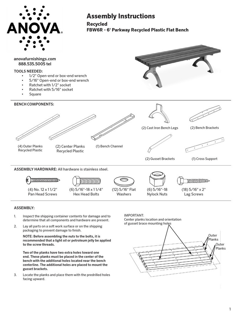
Hardware Required
Wood Deck: 2101714 - SCREW|HEX WSHR HD|#14|1.000 L|BO|TA|SLFT
(2) per mechanism
Aluminum Deck: 2101713 - SCREW|HEX WSHR HD|1/4-14|.813 L|BO|G2|SLFD
(2) per mechanism
Rear Riser: 2101713 - SCREW|HEX WSHR HD|1/4-14|.813 L|BO|G2|SLFD
(2) per mechanism

Metro™ Seating System – Assembly Instructions
Revision R, August 2021 11
This next procedure will be to attach the mechanisms to the riser and deck. This will ensure the chairs are located within the allowable seating
area. In simplest terms you will want to center the amount of chairs within that allowable seating area, between steps or between step and the
end of the bank.
Using the job package drawings for the beam series:
1. Add up the total length of beam(s) plus ¼” for every gap between each beam.
2. Take that calculated length and subtract it from amount of allowable seating in that row you are working on. This amount is the “extra”
space you have to work with.
3. Take that “extra” space dimension and divide that in half. This amount will be used to locate your first gang from either end of the allowable
seating area.
4. The mechanisms, unlock bars and beams that are ganged together can now be moved into position. Secure the first
mechanism in the gang to the deck / riser (see hardware listed above).
5. Once one of the end mechanisms is in its proper place and secured to the deck & riser, secure the second mechanism for this gang
of seating and repeat until all mechanisms in a gang have been secured. Complete the gang by securing the unlock bar clamps near the
center of the gang. This will stop the unlock bar from moving side-to-side.
*The mechanism centerline may be shifted from the centerline of the beam a couple of inches one-way or another if required. The
maximum end beam cantilever distance cannot be greater than 22”.
MECHANISM ATTACHMENT (Lift-Assist & Auto-Fold operation)
(Semi-Automate)
FLOOR MOUNT LAYOUT
FLOOR MOUNT LAYOUT
FLOOR MOUNT LAYOUT
FLOOR MOUNT LAYOUT
FLOOR MOUNT LAYOUT
FLOOR MOUNT LAYOUT
FLOOR MOUNT LAYOUT
FLOOR MOUNT LAYOUT
FLOOR MOUNT LAYOUT
FLOOR MOUNT LAYOUT
FLOOR MOUNT LAYOUT
Assemble units as described. To do otherwise may
result in instability. All screws, nuts and bolts must
be tightened securely and must be checked
periodically after assembly.
Failure to assemble properly, or to secure parts
may result in assembly failure and potential injury.
Assemble units as described. To do otherwise may
result in instability. All screws, nuts and bolts must
be tightened securely and must be checked
periodically after assembly.
Failure to assemble properly, or to secure parts
may result in assembly failure and potential injury.
DO NOT install screws
in these holes
Unlock bar clamps are
only required at one
mechanism location per
gang of chairs.
Target: 1/8” to 1/4” of side to
side unlock bar movement.
Hardware Required
Wood Deck: 2101714 - SCREW|HEX WSHR HD|#14|1.000 L|BO|TA|SLFT
(2) per mechanism
Aluminum Deck: 2101713 - SCREW|HEX WSHR HD|1/4-14|.813 L|BO|G2|SLFD
(2) per mechanism
Rear Riser: 2101713 - SCREW|HEX WSHR HD|1/4-14|.813 L|BO|G2|SLFD
(2) per mechanism

Metro™ Seating System – Assembly Instructions
Revision R, August 2021 12
Once the mechanisms have been attached to the deck and riser, the unlock bar actuators need to be installed.
1. Using a 5mm Allen key remove the bolt at the open end of the actuator. (as shown)
2. Slide the actuator onto the unlock bar. Leave a small gap between the actuator and the mechanism and re-install the previously removed
nut and bolt. Each gang of seating will require (2) actuators, one at each end. These actuators will need to be located inbound of the
mechanisms.
Unlock Bar Actuator (Manual operation)
FLOOR MOUNT LAYOUT
FLOOR MOUNT LAYOUT
FLOOR MOUNT LAYOUT
FLOOR MOUNT LAYOUT
FLOOR MOUNT LAYOUT
FLOOR MOUNT LAYOUT
FLOOR MOUNT LAYOUT
FLOOR MOUNT LAYOUT
FLOOR MOUNT LAYOUT
FLOOR MOUNT LAYOUT
FLOOR MOUNT LAYOUT
2141425 - UNLOCK LEVER|FLD DN MECH|MNL|GEN2|ASSY|BLACK
Exploded View
Assembled View

Metro™ Seating System – Assembly Instructions
Revision R, August 2021 13
Once the mechanisms have been attached to the deck and riser, the unlock bar actuators need to be installed.
1. Slide the actuator onto the unlock bar, leave a small gap between the actuator and the mechanism. (as shown)
2. Using a flat head screw driver, loosen the hose clamp until the loop is open. Place the clamp over the unlock actuator and tighten the strap
around the actuator and the unlock bar. Do not over tighten. Each gang of seating will require (2) actuators, one at each end. These
actuators will need to be located on the right side (looking at the mechanisms) of each end mechanism.
3. Test fit an end cap to make sure the actuator can fit within the end cap cutout.
2147529 - CLAMP|HOSE|WORM
DRIVE|CRES STRAP|21MM-44MM
RANGE|12MM W
SAE No. 20 Hose Clamp
2146479 - ACTUATOR|FLD DN
MECH|UNLK|LIFT-ASSIST|WLD
Unlock Bar Actuator (Lift-Assist & Auto-Fold operations)
FLOOR MOUNT LAYOUT
FLOOR MOUNT LAYOUT
FLOOR MOUNT LAYOUT
FLOOR MOUNT LAYOUT
FLOOR MOUNT LAYOUT
FLOOR MOUNT LAYOUT
FLOOR MOUNT LAYOUT
FLOOR MOUNT LAYOUT
FLOOR MOUNT LAYOUT
FLOOR MOUNT LAYOUT
FLOOR MOUNT LAYOUT
FLOOR MOUNT LAYOUT
FLOOR MOUNT LAYOUT
Assemble units as described. To do otherwise may
result in instability. All screws, nuts and bolts must
be tightened securely and must be checked
periodically after assembly.
Failure to assemble properly, or to secure parts
may result in assembly failure and potential injury.
Assemble units as described. To do otherwise may
result in instability. All screws, nuts and bolts must
be tightened securely and must be checked
periodically after assembly.
Failure to assemble properly, or to secure parts
may result in assembly failure and potential injury.

Metro™ Seating System – Assembly Instructions
Revision R, August 2021 14
Trip Assembly (Auto-Fold operation)
Each gang of Auto-Fold chairs will require two Trip Assemblies to unlock the rows during closing of the bleacher. The closing of the tiers will push
the Trip Assembly up and when connected to the Unlock Bar, this will unlock the rows of seating.
The trip assemblies:
•mounted under the deck starting on 2T
•pass up through holes in the deck
•connect to the unlock bars
Now that you’ve located the holes in the decking (reference Deck Drilling section) the Trip Assemblies can be mounted to the underside. Trip
Assemblies attach to the deck nosing, extend back beyond the rear riser.
1. With the bleacher in the open position, locate the nose plate of the Trip Assembly behind the nosing and attach with the specified
hardware. MAXAM and MXP are different.
2. The pivot/spring mechanism on the long square tube should be in the vertical position and aimed upward.
3. Rotate the long square tube part up closer to the underside of the decking. The pivot/spring portion of the Trip Assembly will go
through the hole previously drilled in the decking.
4. Check that the long square tube is perpendicular to the nosing and the pivot/spring has clearance on all sides as it goes through the
hole in the decking. For best operation, the Trip Assembly can be adjusted side-to-side where it is connected at the nosing. MAXAM
can be moved to the next hole pitch, while MXP is infinitely adjustable.
5. Attachment of this Trip Assembly mechanism to the to the Unlock Bar (above deck) will happen in the next section of this document.
MAXAM Nose Attachment: (2) 1000665 - MACHINE SCREW|HEX HD|3/8-16|1.000
(2) 1000781 - WASHER|SPLT LK|3/8|ZP|G2
(2) 2077817 - NUT|WELD|3/8-16|ZP|T|S1
MXP Nose Attachment: (2) 1000665 - MACHINE SCREW|HEX HD|3/8-16|1.000
(2) 1000781 - WASHER|SPLT LK|3/8|ZP|G2
(2) 2084798 - NUT|CHAN|3/8-16|ZP
MAXAM Trip Assembly
MXP Trip Assembly
Relocate the pivot/spring portion of
the trip assembly to the front most
hole when using rear riser spacer.

Metro™ Seating System – Assembly Instructions
Revision R, August 2021 15
Trip Assembly Deflector (Auto-Fold operation)
The trip mechanisms, in most cases, will be actuated by either the riser on the lower tier or the riser filler. Custom rises that do not require riser
fillers, will need to have a trip mechanism deflector installed.
MAXAM with 11 5/8R, 16R or custom rise
The Trip Assemblies are actuated by contact with the rear riser on 9 5/8R. With other rise situations a Deflector is required to be installed.
1. Locate one Deflector in line with each of the long square tube of the Trip Assembly and flush to the bottom edge of the rear riser.
2. Attach the Deflector to the rear riser with (2) self-drilling screws.
Rear Riser: 2101713 - SCREW|HEX WSHR HD|1/4-14|.813 L|BO|G2|SLFD
(2) per deflector
Trip Assembly Deflector
11 5/8R –P/N 2165390
16R –P/N 2165401

Metro™ Seating System – Assembly Instructions
Revision R, August 2021 16
2147529 - CLAMP|HOSE|WORM
DRIVE|CRES STRAP|21MM-44MM
RANGE|12MM W
SAE No. 20 Hose Clamp
2146478 - ACTUATOR|FLD DN
MECH|UNLK|AUTO-FOLD|WLD
Unlock Bar Actuator (Auto-Fold operation)
Now that the Trip Assemblies have been attached to the nosing, the Unlock Bar Actuators can be assembled to the Unlock Bars.
1. Slide the Actuator onto the unlock bar. The pin of this Actuator will be assembled to the pivot/spring portion of the Trip Assembly
sticking up through the hole in the decking.
2. Remove the cotter pin and one washer from the Actuator and slide this through the hole of the pivot/spring portion of the Trip
Assembly.
3. Re-assemble the washer and cotter pin to the Actuator.
4. Move the Actuator side-to-side to make sure the pivot/spring will be located in the center of the hole in the decking.
5. Using a flat head screwdriver, loosen the hose clamp until the loop is open. Place the clamp over the unlock Actuator and tighten
the strap around the Actuator and Unlock Bar. Do not over tighten. Each gang of seating will require (2) Actuators, one at each Trip
Assembly location.

Metro™ Seating System – Assembly Instructions
Revision R, August 2021 17
Armrest assemblies will be located at the “aisle end” of the beam and between each chair module throughout the row.
1. Locate the first armrest on the beam, rotate the armrest clamp into position and tighten armrest clamp with M6 hex key bit.
2. Using the Center-to-Center dimensions from job package drawing, locate and fasten the remainder of armrests on beam.
3. When seating rows have more than one beam, double armrests are not supplied. An armrest will be attached to one side of the gap in the
beam while the other side of the gap in the beam will remain without an arm. The patron on each side of the gap will share this armrest.
4. If the rise of the stand is less than 11 5/8” it may be necessary to install arm assemblies with glides. The assemblies with glides (factory
Installed) prevent interference between the arm and the nose on the tier above. They should be installed within the seat gang closest to the
1/3 points and not at the ends.
Assemble units as described. To do otherwise may
result in instability. All screws, nuts and bolts must
be tightened securely and must be checked
periodically after assembly.
Failure to assemble properly, or to secure parts
may result in assembly failure and potential injury.
Assemble units as described. To do otherwise may
result in instability. All screws, nuts and bolts must
be tightened securely and must be checked
periodically after assembly.
Failure to assemble properly, or to secure parts
may result in assembly failure and potential injury.
Division of Chair Gang in Thirds for Glide Alignment
ARMREST INSTALLATION
FLOOR MOUNT LAYOUT
FLOOR MOUNT LAYOUT
FLOOR MOUNT LAYOUT
FLOOR MOUNT LAYOUT
FLOOR MOUNT LAYOUT
FLOOR MOUNT LAYOUT
FLOOR MOUNT LAYOUT
FLOOR MOUNT LAYOUT
FLOOR MOUNT LAYOUT
FLOOR MOUNT LAYOUT
Center –To –Center Dimensions of Armrests
Glide

Metro™ Seating System – Assembly Instructions
Revision R, August 2021 18
Once mechanisms are working to satisfaction, dust covers and end caps can be installed. Dust covers come pre-cut to the mechanism
spacings. Refer to chart for cut lengths.
1. Install end caps on the end mechanism. Attach each end cap to both the riser and the deck with (2) fasteners. Be sure that tabs of end
caps are inserted fully into the oval holes in the wall of the mechanism.
•If Lift-Assist & Auto-Fold, add end cap w/cutout
2. Slide the proper length dust cover behind the end cap.
3. Install the next set of end caps similar to step 1.
4. Center the dust cover between the end caps. Be sure that the dust cover fits tight against the inside edge of the end caps without gaps.
Attach the dust cover to the riser with (3) self-drilling screws. Repeat all steps until the covers and end caps in the gang have been installed.
Hardware Required
End Cap: 2101713 - SCREW|HEX WSHR HD|1/4-14|.813 L|BO|G2|SLFD - (1) per end cap (Riser)
2101713 - SCREW|HEX WSHR HD|1/4-14|.813 L|BO|G2|SLFD - (1) per end cap (Aluminum Deck)
2101714 - SCREW|HEX WSHR HD|#14|1.000 L|BO|TA|SLFT –(1) per end cap (Wood Deck)
Dust Cover: 2101713 - SCREW|HEX WSHR HD|1/4-14|.813 L|BO|G2|SLFD –(3) per mechanism (Riser)
Attach End Caps (End Mechanism)
Slide Dust Cover
Attach End Caps (Next Mechanism)
Attach Dust Cover
End cap cutout
required on
Lift -Assist &
Auto-Fold
Ensure tight fit along this
edge before attaching to the
riser (Both ends)
DUST COVER INSTALLATION Lift-Assist (shown) and Auto-Fold (similar)
FLOOR MOUNT LAYOUT
FLOOR MOUNT LAYOUT
FLOOR MOUNT LAYOUT
FLOOR MOUNT LAYOUT
FLOOR MOUNT LAYOUT
FLOOR MOUNT LAYOUT
FLOOR MOUNT LAYOUT
FLOOR MOUNT LAYOUT
FLOOR MOUNT LAYOUT
FLOOR MOUNT LAYOUT

Metro™ Seating System – Assembly Instructions
Revision R, August 2021 19
Adding the tablet assemblies to the armrests needs to be completed prior to installing chair modules.
1. Layout the tablet assemblies on the deck using the job package drawings. These tablet assemblies are handed and will be shown as right
and or left hand operation.
2. Secure the tablet assembly to the armrest assembly using the hardware listed above.
3. Raise the tablet to the “used” position, laying the writing surface over the armrest as if patron was prepared to use the tablet. Lift and
release the tablet assembly to drop to the “stored” position up against the beam. Make sure the tablet goes through its motion in a
controlled manner. The torque in the tablet is controlled by the adjustment screw located on the tablet assembly. The torque has been
pre-set at the factory but can be adjusted when required. Turning the screw clockwise will slow the motion of the tablet.
TABLET SYSTEM INSTALLATION
FLOOR MOUNT LAYOUT
FLOOR MOUNT LAYOUT
FLOOR MOUNT LAYOUT
FLOOR MOUNT LAYOUT
FLOOR MOUNT LAYOUT
FLOOR MOUNT LAYOUT
FLOOR MOUNT LAYOUT
FLOOR MOUNT LAYOUT
FLOOR MOUNT LAYOUT
FLOOR MOUNT LAYOUT
Assemble units as described. To do otherwise may
result in instability. All screws, nuts and bolts must
be tightened securely and must be checked
periodically after assembly.
Failure to assemble properly, or to secure parts
may result in assembly failure and potential injury.
Assemble units as described. To do otherwise may
result in instability. All screws, nuts and bolts must
be tightened securely and must be checked
periodically after assembly.
Failure to assemble properly, or to secure parts
may result in assembly failure and potential injury.
Assemble units as described. To do otherwise may
result in instability. All screws, nuts and bolts must
be tightened securely and must be checked
periodically after assembly.
Failure to assemble properly, or to secure parts
may result in assembly failure and potential injury.
Assemble units as described. To do otherwise may
result in instability. All screws, nuts and bolts must
be tightened securely and must be checked
periodically after assembly.
Failure to assemble properly, or to secure parts
may result in assembly failure and potential injury.
Assemble units as described. To do otherwise may
result in instability. All screws, nuts and bolts must
be tightened securely and must be checked
periodically after assembly.
Failure to assemble properly, or to secure parts
may result in assembly failure and potential injury.
Assemble units as described. To do otherwise may
result in instability. All screws, nuts and bolts must
be tightened securely and must be checked
periodically after assembly.
Failure to assemble properly, or to secure parts
may result in assembly failure and potential injury.
Assemble units as described. To do otherwise may
result in instability. All screws, nuts and bolts must
be tightened securely and must be checked
periodically after assembly.
Failure to assemble properly, or to secure parts
may result in assembly failure and potential injury.
Assemble units as described. To do otherwise may
result in instability. All screws, nuts and bolts must
be tightened securely and must be checked
periodically after assembly.
Failure to assemble properly, or to secure parts
may result in assembly failure and potential injury.
Assemble units as described. To do otherwise may
result in instability. All screws, nuts and bolts must
be tightened securely and must be checked
periodically after assembly.
Failure to assemble properly, or to secure parts
may result in assembly failure and potential injury.
Assemble units as described. To do otherwise may
result in instability. All screws, nuts and bolts must
be tightened securely and must be checked
periodically after assembly.
Torque Adjust Screw
2098240 - CAP SCREW|SCKT HD|M6 X 1.0|20MM
L|ZP
Q000511 - WASHER|M6|SPLT LK|ZP
L|ZP
2101719 - NUT|SCKT FL HD|M6 X
1.0|JOINT CONN|7MM L|BZ
L|ZP

Metro™ Seating System – Assembly Instructions
Revision R, August 2021 20
With the armrests installed at the proper center-to-center dimensions, the chair module installation can begin.
1. Slide the chair module over the back portion of the beam between two armrests.
2. Rotate the chair module forward and up to snap the module into the initial position on the beam.
3. Center the chair module between the armrests and tighten / torque the two module clamp bolts with a M6 hex key bit. The torque
requirement shown above will ensure the chair modules are not over tightened and will not loosen after installation is completed.
Assemble units as described. To do otherwise may
result in instability. All screws, nuts and bolts must
be tightened securely and must be checked
periodically after assembly.
Failure to assemble properly, or to secure parts
may result in assembly failure and potential injury.
Assemble units as described. To do otherwise may
result in instability. All screws, nuts and bolts must
be tightened securely and must be checked
periodically after assembly.
Failure to assemble properly, or to secure parts
may result in assembly failure and potential injury.
Assemble units as described. To do otherwise may
result in instability. All screws, nuts and bolts must
be tightened securely and must be checked
periodically after assembly.
Failure to assemble properly, or to secure parts
may result in assembly failure and potential injury.
Assemble units as described. To do otherwise may
result in instability. All screws, nuts and bolts must
be tightened securely and must be checked
periodically after assembly.
Failure to assemble properly, or to secure parts
may result in assembly failure and potential injury.
Assemble units as described. To do otherwise may
result in instability. All screws, nuts and bolts must
be tightened securely and must be checked
periodically after assembly.
Failure to assemble properly, or to secure parts
may result in assembly failure and potential injury.
Assemble units as described. To do otherwise may
result in instability. All screws, nuts and bolts must
be tightened securely and must be checked
periodically after assembly.
Failure to assemble properly, or to secure parts
may result in assembly failure and potential injury.
Assemble units as described. To do otherwise may
result in instability. All screws, nuts and bolts must
be tightened securely and must be checked
periodically after assembly.
Failure to assemble properly, or to secure parts
may result in assembly failure and potential injury.
Assemble units as described. To do otherwise may
result in instability. All screws, nuts and bolts must
be tightened securely and must be checked
periodically after assembly.
Failure to assemble properly, or to secure parts
may result in assembly failure and potential injury.
Assemble units as described. To do otherwise may
result in instability. All screws, nuts and bolts must
be tightened securely and must be checked
periodically after assembly.
Failure to assemble properly, or to secure parts
may result in assembly failure and potential injury.
Assemble units as described. To do otherwise may
result in instability. All screws, nuts and bolts must
be tightened securely and must be checked
periodically after assembly.
Do not use any type of impact driver to
tighten chair modules to the beam.
Damage to the module will result.
Torque setting from 110 to 130 in-lbs max
Do not use any type of impact driver to
tighten chair modules to the beam.
Damage to the module will result.
Torque setting from 110 to 130 in-lbs max
Do not use any type of impact driver to
tighten chair modules to the beam.
Damage to the module will result.
Torque setting from 110 to 130 in-lbs max
Do not use any type of impact driver to
tighten chair modules to the beam.
Damage to the module will result.
Torque setting from 110 to 130 in-lbs max
Do not use any type of impact driver to
tighten chair modules to the beam.
Damage to the module will result.
Torque setting from 110 to 130 in-lbs max
Do not use any type of impact driver to
tighten chair modules to the beam.
Damage to the module will result.
CHAIR MODULE INSTALLATION
FLOOR MOUNT LAYOUT
FLOOR MOUNT LAYOUT
FLOOR MOUNT LAYOUT
FLOOR MOUNT LAYOUT
FLOOR MOUNT LAYOUT
FLOOR MOUNT LAYOUT
FLOOR MOUNT LAYOUT
FLOOR MOUNT LAYOUT
FLOOR MOUNT LAYOUT
Table of contents
Other Hussey Seating Outdoor Furnishing manuals
Popular Outdoor Furnishing manuals by other brands

Muddy
Muddy The Renegade MQP1500 instruction manual

highwood
highwood Sequoia Professional CM-TBLSQ36 Assembly guide

Kozyard
Kozyard KZF606 Assembly manual

Anchor Fast
Anchor Fast Wooden Grilling Pavilion quick start guide

Amerihome
Amerihome ABGLIDER4 Assembly instructions

sweeek.
sweeek. MOOREA IMOOARM manual

real living
real living OAKMONT GB21-617 Assembly instruction

Hartman
Hartman Amalfi 60903062 Assembly instructions

Patio Post
Patio Post SS63002 Assembly instruction

Weka
Weka B607.003 ASSEMBLY, USER AND MAINTENANCE INSTRUCTIONS

Outdoor living today
Outdoor living today 8x8 Sunshed Garden Shed Assembly manual

real living
real living Oakmont GB19-528 Assembly instruction