HUYU H8M Series Owner's manual

Electrical
Safety Guard
H8M Series
Molded Case Circuit Breaker
Installation and Operation
Instruction
Product Certificate
This product has passed the inspections and meets the
requirements of GB/T 14048.2, and therefore is allowed to
leave the factory.
Inspector:
Date of inspection: See the product or packaging.
Huanyu Group Zhejiang High-tech Co., Ltd.
Inspection
08

- 1 -
The H8M Series Molded Case Circuit Breaker (hereinafter referred to as
“circuit breaker”) is the high-tech product in the 21st century. This product is
characterized by advanced design, reliable performance, high technical
indicators, beautiful appearance, and small size.
1 Purpose and Scope of Application
This circuit breaker is suitable for the power system with AC 50 Hz, rated
isolation voltage up to 800 V, rated working voltage up to 690 V and rated
current up to 800 A. It is used to distribute electric energy and protect
circuits and power supply equipment from overload, short circuit,
undervoltage and other faults, and to prevent the infrequent operation of
the motor.
2 Standards Followed
The product complies with GB/T 14048.2-2008 Low-voltage Switchgear and
Controlgear — Part 2: Circuit-breakers and IEC 60947-2 Low-voltage
Switchgear and Controlgear — Part 2: Low-voltage Circuit Breakers, etc.
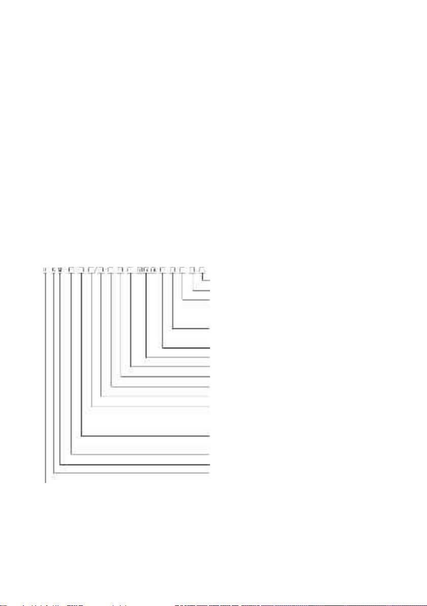
3 Model Description
Overload alarm without tripping is denoted by “I”
Flashover distance: No code with flashover; Code W without flashover
Wiring method
:
No code with wiring in front of the plate; Code H with
wiring behind the plate, C for plug-
in connection, and
CH for pull-out connection (only for 3 poles)
No code for conventional products, and code Y with the special release
with prepaid kilowatt
-hour meter
Application code: No code for power distribution; Code 2 for motor protection
Internal accessory code (see Table
2)
Overcurrent release type (see Table 1)
Type of neutral pole (N pole) of 4
-pole circuit breaker (note)
Number of poles of circuit breaker: 3 for 3 poles; 4 for 4 poles
Circuit breaker rated current In (A) (see Table 3)
Operation mode:
No code for handle direct operation;
Code M for electrical operation;
Code Z for handle rotation operation
Short
-circuit breaking capacity level: C — Basic type; S — Standard type;
H
— Advanced type; U — Current limiting type
Shell frame level rated current Inm (A) (see Table 3)
Molded
Case Circuit Breaker
Design number
Enterprise code
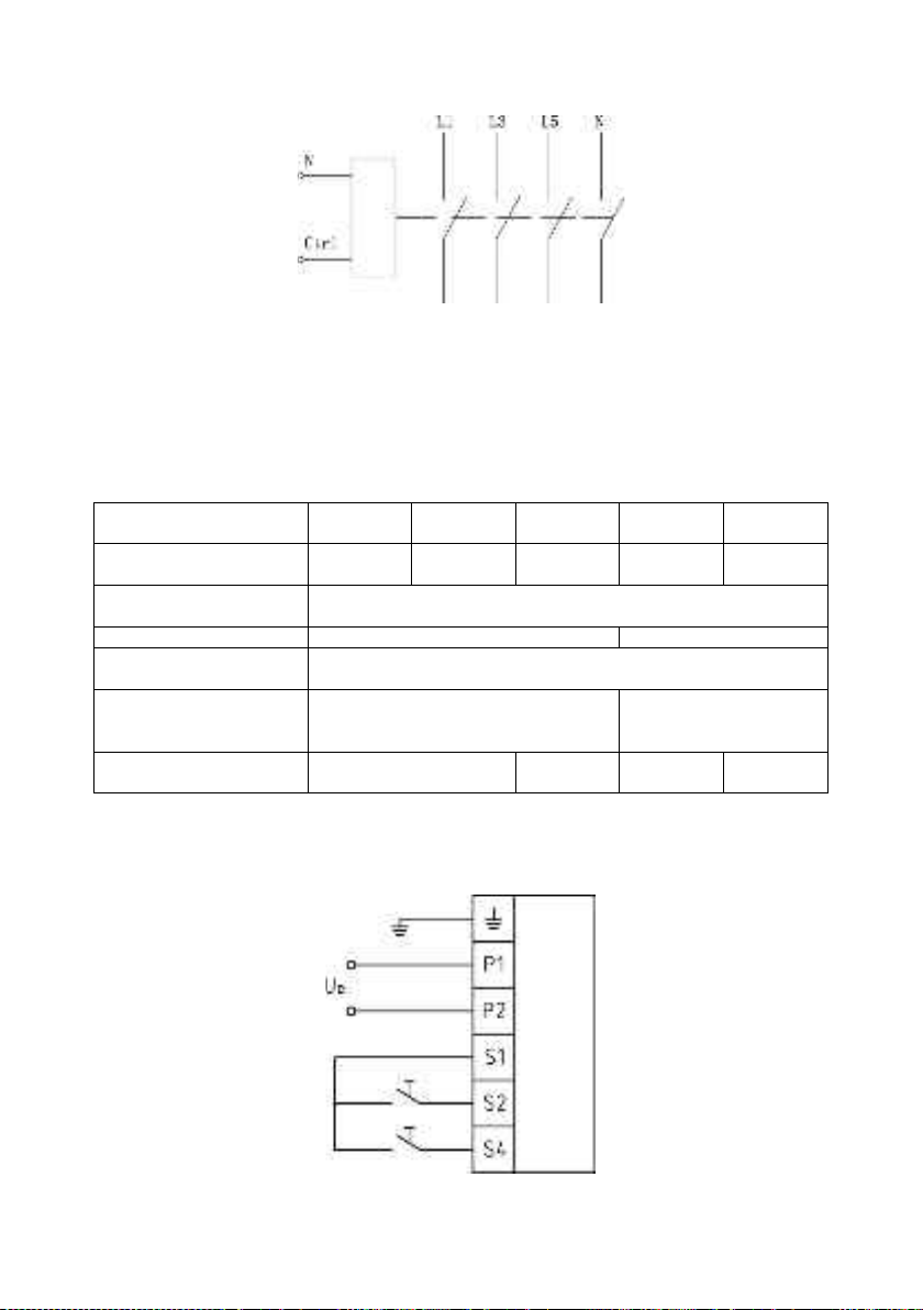
Note: In 4-pole products, two types are provided for the neutral pole (N pole):
Type A: The N pole is not equipped with an overcurrent release and is normally on, and
is not opened/closed with the other three poles.
Type B: The N pole is not equipped with an overcurrent release, and is closed/opened
with the other three poles.

- 2 -
Table 1 Type of overcurrent release
Serial
number
Name Description
1
Delay release
With the overcurrent inverse time limit protection characteristic
2
Instantaneous
release
i.e. electromagnetic release, with the overcurrent instantaneous
operation protection characteristic
3
Complex
release
With the above two functions
Table 2 Internal accessory code
Inm
(A)
I
II
III
Notes
Code
Description
Code
Description
Code
Description
63
100
250
0
N/A
0~2
Number of
auxiliary
contacts
0~2
Number of
alarm
contacts
1
Shunt trip
0~1
0~1
2
Undervoltage
release
0~1 0~1
400
0
N/A
0~5
0~2
II+III≤7
1
Shunt trip
0~3
0~2
II+III≤5
2
Undervoltage
release
0~3 0~2 II+III≤5
3
Shunt/Undervoltage
release
0~1 0~1 II+III≤2
630
800
0
N/A
0~8
0~3
II+III≤11
1
Shunt trip
0~6
0~3
II+III≤8
2
Undervoltage
release
0~6 0~3 II+III≤8
3
Shunt/Undervoltage
release
0~3 0~2 II+III≤5
4 Normal Working Conditions
The circuit breaker is suitable for the following working conditions:
4.1 The ambient air temperature shall not be higher than +40°C or lower
than -5°C.
4.2 Altitude ≤ 2,000 m.
4.3 The relative air humidity shall not exceed 50% at the maximum
temperature of +40°C. A higher relative humidity is allowed at a lower
temperature. The average minimum temperature of the wettest month
shall not exceed +25°C, and the average maximum relative humidity of
that month shall not exceed 90%.
4.4 Contamination grade: Grade 3. There is no explosion danger and no
gas or conductive dust that corrodes metals or damages insulation in
the surrounding air.
4.5 The installation category is Grade III.
4.6 The "1, 3, 5 and N1" terminals of the circuit breaker are connected to
the power supply, and the "2, 4, 6 and N2" terminals are connected to
the load, which cannot be reversed.
4.7 The installation surface of the circuit breaker shall be vertical to the
horizontal plane. The circuit breaker is basically installed vertically, with
the power supply terminal at the top and the load terminal at the bottom,
and can also be installed horizontally.

- 3 -
5 Main Technical Performance Indicators
5.1 The main technical performance indicators are shown in Table 3.
Table 3 Main technical performance indicators
Shell frame level rated current
Inm (A)
63 100 250
Product model
H8M-
63S
H8M-
100C
H8M-100S
H8M-
100H
H8M-
100U
H8HM-
250C
H8M-
250S
H8M-
250H
H8M-
250U
Rated current In (A)
10,16,20
25,32,40
50,63
16,25,32,40,50,63,80,100 100,125,150,160,175,200,225,250
Number of poles
3
3
4
3
4
3
3
3
4
3
4
3
3
Rated insulation voltage Ui (V)
AC 600
AC 800
AC 800
Rated impulse withstand
voltage Uimp (kV)
8
Flashover distance (mm)
≤50(0)*
≤50 (0) *
≤50 (0) *
Rated
ultimate/service
short-circuit
breaking
capacity Ics (kA)
690 V
-
-
5/3
10/5
10/5
-
5/5
10/5
10/5
400 V 35/35 35/35 55/55 85/85 125/
125 35/35 55/55 85/85 125/
125
Operation
performance
(times)
Energizing
8,000
8,000
8,000
De-energizing
20,000
20,000
20,000
Outline dimensions
(mm)
a
75
90
120
90
120
90
90
105
140
105
140
105
105
b
130
155
216
165
240
c 68 68 68
Installation dimensions
(mm)
A
25
30
35
B
111
132
193
126
201
Φ5 5 5
* The flashover distance, if zero, shall be indicated when ordering.

- 4 -
Table 3 Main technical performance indicators (completed)
Shell frame level rated
current Inm (A) 400 630 800
Product model H8M-
400C
H8M-
400S
H8M-
400H
H8M-
400U
H8M-
630C
H8M-
630S
H8M-
630H
H8M-
630U
H8M-
800C
H8M-
800S
H8M-
800H
H8M-
800U
Rated current In (A)
250,300,350,400
400,500,630
630,700,800
Number of poles
3
4
3
4
3
3
3
4
3
4
3
3
3
4
3
4
3
3
Rated insulation
voltage Ui (V)
AC 800 AC 800 AC 800
Rated impulse
withstand voltage Uimp
(kV)
8
Flashover distance
(mm) ≤100 (0) * ≤100 <0) * ≤100 (0) *
Rated
ultimate/
service
short
-
circuit
breaking
capacity
Icu/Ics
(kA)
690 V 10/10 10/10
15/10
35/35 10/10 15/15 20/15 35/35
10/10 15/15 20/15 35/35
400 V 50/50 75/75
100/
100
125/
125 50/50 75/75 100/
100
125/
125 50/50 75/75 100/
100
125/
125
Operation
performance
(times)
Energizing
7,500
7,500
7,500
De-
energizing 10,000 10,000 10,000
Outline
dimensions (mm)
a
140
185
140
180
140 140
210
280
210
280
210 210
210
280
210
280
210 210
b 257 297 275 322 275 322
c 103 200 103 200 103 200
Installation
dimensions (mm)
A 44 70 70
B 194 234 243 290 243 290
Φ7 7 7
* The flashover distance, if zero, shall be indicated when ordering.
5.2 See Table 4 (for power distribution) and Table 5 (for motor) for the
overcurrent protection characteristics.
Table 4 Overcurrent protection characteristics of circuit breakers for
power distribution
Rated current In
(A)
Thermal release (ambient temperature +40°C)
Operating current of
electromagnetic release
(A) [Note]
1.05 In non-operating time (h)
(initial state: cold state)
1.30 In operating time (h)
(initial state: thermal state)
≤63
>1
≤1
(10±2)In
>63
>2
≤2

- 5 -
Table 5 Overcurrent protection characteristics of circuit breakers for
motors
Rated current In
(A)
Thermal release (ambient temperature +40°C)
Operating current
of
electromagnetic
release (A) [Note]
1.0 In non-
operating time
(h)
(initial state: cold
state)
1.2 In operating
time (h)
(initial state:
thermal state)
1.5 In operating
time (min)
(initial state:
thermal state)
7.2 In operating
time (s)
(initial state: cold
state)
In≤63
>2 ≤2
≤2
2<Tp≤10
(12±2.4)In63<In≤250 ≤4 4<Tp≤10
250<In≤800
≤8
6<Tp≤20
[Note]: The operating current of the electromagnetic release of H8M-630 and 800 (400 A ≤ In ≤
800 A) is (5±1) In to 14 In.
Adjustable reference value: Low (4 ~ 6) In; Relatively low (6 ~ 8.3) In; Relatively high (8.3 ~ 10.9)
In; High (10.9 ~ 14) In.
6 Circuit Breaker Accessories
6.1 List of accessory models (see Table 6).
Table 6 List of accessory models
Shell frame level rated current Inm
(A)
63 100 250 400 630, 800
Internal accessories
Alarm contact B1 B2 B3 B4
Auxiliary contact
F1
F2
F3
F4
Shunt trip
FL1
FL2
FL3
FL4
Undervoltage release QY1 QY2 QY3 QY4
Accessory terminal JX
Special release with prepaid
kilowatt-hour meter
Y
External
accessories
Rotation operating handle
CS1-63
CS1-100
CS1-250
CS1-400
CS1-630
Electric operating mechanism
MDX0
MDX1
MDX2
MDX3
MDX4
Mechanical
interlock
3-pole N1-3 N2-3 N3-3 N4-3 N5-3
4-pole
——
N2-4
N3-4
N4-4
N5-4
6.2 Rated values of auxiliary contacts and alarm contacts
Conventional thermal current Ith = 6 A;
Rated working current Ie = 0.79 A (230 V, AC) Ie = 0.47 A (400 V, AC);
Ie = 0.15 A (220 V, DC).
6.3 Shunt trip parameters
Rated voltage Us: AC: 110 V, 230 V, 400 V; input capacity: 180 VA;
DC: 24 V, 48 V, 110 V; input capacity: 60 W.
The circuit breaker can interrupt reliably under (70% ~ 110%) Us, and
the operating time is 10 ms ~ 30 ms.

- 6 -
When the rated control power supply voltage of the shunt trip is DC 24 V, the
maximum length of the copper conductor shall meet the requirements of
Table 7.
Table 7 Maximum length of the copper conductor
Conductor area
Rated control
power supply voltage
Uc (DC 24 V)
1.5mm22.5mm2
100% Uc
150m
250m
80% Uc
100m
160m
If the requirements of the above table are not met, it is recommended to
design the control circuit of the shunt trip according to Figure 1.
Inside the dotted line box is the
schematic diagram of the shunt
trip
Power supply input
KA: DC24V. The current
capacity of the
intermediate relay
contact is 1 A.
The voltage of the input terminal of the
power supply is: AC 50 Hz 230 V, 400 V
Figure 1 Shunt trip control circuit design
6.4 Parameters of the undervoltage release
Rated voltage Ue: AC: 110 V, 230 V, 400 V;
DC: 24 V, 48 V, 110 V.
The circuit breaker can interrupt reliably under (35%~70%) Us, and the
operating time is 10 ms~30 ms. When the power supply voltage is less than
35% Ue, the circuit breaker can be prevented from closing. When the power
supply voltage is more than or equal to 85%, the circuit breaker can be
reliably closed.
6.5 Special release with prepaid kilowatt-hour meter
The rated working voltage Ue of the special release with prepaid kilowatt-
hour meter is AC 240 V/50 Hz. It can work normally in the range of
(65%~110%) Ue. When the Ctrl terminal is cut off, the breaker will delay
opening by 0.5 s ~ 2 s. See Figure 2 for the wiring diagram.

- 7 -
Note: N is connected to the power neutral wire, and Ctrl is connected to the control signal
terminal of the prepaid kilowatt-hour meter.
Figure 2 Wiring diagram of the special release with prepaid watt-hour
meter
6.6 See Table 7 for the parameters of the electric operating mechanism.
Table 7 Main technical parameters of the MDX Electric Operating
Mechanism
Shell frame level rated
current Inm (A)
63 100 250 400 630, 800
Model of electric
operating mechanism
MDX0 MDX1 MDX2 MDX3 MDX4
Rated working voltage
Ue (V)
AC 110 V~230 V, 50 Hz; DC 110V ~220 V
Starting current (A)
≤0.5
≤2
Operating time
(S)
≤0.8
Rated operating
frequency
(times/h)
180 120
Mechanical life
(times)
15,000 9,000 5,000 3,000
The power supply capacity of the electric operating mechanism shall be large
enough to ensure that the voltage applied to the electric operating
mechanism under the starting current is not less than 85% Ue.
6.7 See Figure 1 for the wiring diagram of the electric operating mechanism.
Figure 1 Wiring diagram of the MDX Electric Operating Mechanism
Release
Circuit breaker
L1-N
Rated working voltage Ue
of Ctrl-N: AC 240 V/50 Hz
MDX type
Closed
Open

- 8 -
7 Use and Maintenance
7.1 Considerations before installation of the circuit breaker
The appearance of the circuit breaker is in good condition, and no-load
operation works normally.
The insulation resistance between the poles of the circuit breaker and
the incoming and outgoing line terminals of the same pole in the
interrupting state shall not be less than 1.5 MΩ.
The rated values of the circuit breaker and its accessories shall be
consistent with the working conditions of the installation site.
There shall be no significant impact vibration at the installation, which
meets the normal working conditions.
7.2 The cross-section area of the connecting conductor of the circuit breaker
shall not be less than that specified in Table 8, and the connecting
screws shall be tightened.
Table 8 Cross-section area of the connecting conductor
Rated current In
(A)
10
16
20
32
40
50
63 80 100
125
150
160
175
200
225
250
300
350
400
Cross-section
area of the
conductor
(mm
2
)
1.5 2.5 6 10 16 25 35 50 70 95 120 185 240
Rated current In
(A)
500 630 700, 800
Copper
conduct
or
Pcs
2
2
2
Cross-section
area
(mm
2
)
150 185 240
Copper
busbar
Pcs
2
2
2
Cross-section
area
(mm
2
)
30×5 40×5 50×5
7.3 Various characteristics of the circuit breaker and its accessories are set
by our company according to the order requirements, and cannot be
adjusted freely during use.
7.4 The handle of the circuit breaker can be in three positions: "Closed",
"Open" and "Tripped". When the handle is in the trip position, it shall be
pulled in the "Open" direction to make the circuit breaker trip again, and
then the "Closing" operation can be carried out.
7.5 During the installation of the internal accessories, the circuit breaker
must be tripped and interrupted before installation.

Company Commitment
On the premise that users abide by the use and storage conditions and that
the product seals are intact, if the product is damaged or cannot be used
normally due to manufacturing quality problems within 18 months from the
production date of the product, our company will be responsible for the
repairing or replacement free of charge. If the warranty period expires, users
shall pay for the repair. However, if the damage is caused by the following
circumstances, the fees for repair still shall be charged even within the
warranty period:
(1) Misuse, self-modification, improper maintenance, etc.
(2) Use beyond the standard specification requirements.
(3) Falling, damage during transportation, etc. after purchase.
(4) Earthquake, fire, lightning strike, abnormal voltage, other natural
disasters and secondary disasters, etc.
In case of any questions, please contact the dealer or our customer service
department.
Dear customers:
To protect our environment, please recycle the product or its components
when the product is scrapped. For materials that cannot be recycled, please
handle them properly. Thank you very much for your cooperation and
support.

Huanyu Group Zhejiang High-tech Co., Ltd.
Address: Wenzhou Bridge Industrial Zone, Yueqing City, Zhejiang Province
Tel.: 0577-62889999
Fax: 0577-62885588
Postal code: 325603
http://www.huyu.coin.cn
Service Hotline 400-887-5757
This manual suits for next models
9
Table of contents
Other HUYU Circuit Breaker manuals
Popular Circuit Breaker manuals by other brands

hager
hager XEVS020 Replacement manual

Siemens
Siemens SION 3AE-Z M30 Service & Maintenance

TAVRIDA ELECTRIC
TAVRIDA ELECTRIC ISM_LD Series Application guide

FEDERAL PACIFIC
FEDERAL PACIFIC FUSEMATIC FP25-600 instruction manual

GE
GE Spectra Series installation instructions

Siemens
Siemens SIRIUS 3RV2.4 Original operating instructions