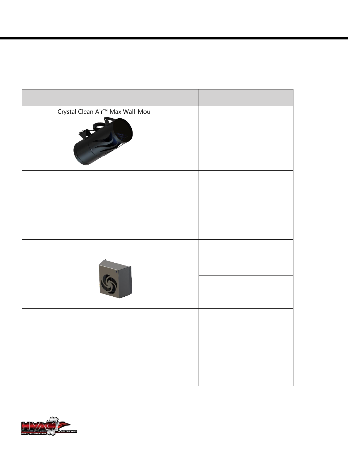
Hvac Crystal Clean Air IAA073M1-02 User manual

CRYSTAL CLEAN AIRTM
Ionization Unit
Installation Manual
Crystal Clean Air™ Ionization Unit Max Wall-Mounted
Crystal Clean Air™ Ionization Unit Max Ceiling-Mounted
Crystal Clean Air™Mini Wall/Ceiling-Mounted
Crystal Clean Air™
Micro

2
Due to our policy of continuous product innovation, some specifications may change without notification.
©HVAC MANUFACTURING AND TECHNOLOGY, Inc., Athens TX. All rights reserved. .
PROPRIETARY DATA NOTICE
This document, as well as all reports, illustrations,
data, information, and other materials are the
property of ©HVAC MANUFACTURING AND
TECHNOLOGY, Inc.
Do not throw away, destroy, or lose this manual.
Please read carefully and store in a safe place for
future reference. Content familiarity required for
proper installation.
The instructions included in this manual must be followed to
prevent product malfunction, property damage, injury, or
death to the user or other people. Incorrect operation due
to ignoring any instructions will cause harm or damage. A
summary of safety precautions begins on page 4.
For more technical materials such as submittals,
engineering data books, and catalogs, visit
www.hvacmfg.com.

3
Due to our policy of continuous product innovation, some specifications may change without notification.
©HVAC MANUFACTURING AND TECHNOLOGY, Inc., Athens TX. All rights reserved. .
Table of Contents
Safety Instructions...................................................................................................................................................... 4
Table of Symbols ........................................................................................................................................................4
Installation..................................................................................................................................................................... 4
Safety Instructions...................................................................................................................................................... 5
Products .........................................................................................................................................................................6
Tools and Materials ................................................................................................................................................... 7
Required Parts (factory provided) ........................................................................................................7
Required Materials for Max, Mini, and Micro (field provided) .........................................................7
Tools Consider for Installation (field provided)..................................................................................7
Unit Nomenclature..................................................................................................................................................... 8
General Data............................................................................................................................................9
Electrical Data........................................................................................................................................10
Crystal Clean Air™ Mini ..........................................................................................................................................11
General Data..........................................................................................................................................11
Electrical Data........................................................................................................................................12
Crystal Clean Air Accessories ...............................................................................................................................13
Crystal Clean Air Max 10" ....................................................................................................................14
External Dimensions (inches) ..............................................................................................................14
Crystal Clean Air Max 10"......................................................................................................................................14
External Dimensions (inches) ...............................................................................................................................14
Crystal Clean Air Mini...........................................................................................................................14
External Dimensions (inches) ..............................................................................................................14
Ionization Placement & Clearance.....................................................................................................................15
Required Clearances for Max Wall Mounted Unit............................................................................15
Required Clearances for Max Ceiling Mounted Unit .......................................................................15
Ionization Placement & Clearance.....................................................................................................................16
Required Clearances for Mini Wall Mounted Unit ...........................................................................16
Required Clearances for Max Ceiling Mounted Unit .......................................................................16
Installation Max Wall-Mounted Unit.................................................................................................................18
Installation Mini Wall/Ceiling-Mounted Units..................................................................................19
Maintenance...............................................................................................................................................................20

4
Due to our policy of continuous product innovation, some specifications may change without notification.
©HVAC MANUFACTURING AND TECHNOLOGY, Inc., Athens TX. All rights reserved. .
Safety Instructions
The instructions below must be followed to prevent product malfunction, property damage, injury or
death to the user or other people. Incorrect operation due to ignoring any instructions will cause
harm or damage. The level of seriousness is classified by the symbols below.
Table of Symbols
DANGER
This symbol indicates an imminently hazardous situation which, if not avoided, will result in
death or serious injury.
WARNING
This symbol indicates a potentially hazardous situation which, if not avoided, could result in
death or serious injury.
CAUTION
This symbol indicates a potentially hazardous situation which, if not avoided, may result in
minor or moderate injury.
Note:
This symbol Indicates situations that may result in equipment or property damage accidents
only.
This symbol indicates an action that must not be performed.
Installation
DANGER
Do not use or store flammable gas or combustibles near the unit. There is risk of product failure, fire,
explosion, and physical injury or death.
WARNING
Do not install, remove the unit by yourself
(customer). Ask an authorized technician to install
the unit.
Improper installation by the user may result in
electric shock, physical injury.
For replacement of an installed unit, always
contact a trained service provider.
Do not install the unit using defective hanging,
attaching, or mounting hardware.
There is risk of physical injury or death.
Dispose the packing materials safely.
•
Packing materials, such as nails and other metal
or wooden parts may cause puncture wounds
or other injuries.
Tear apart and throw away plastic packaging
bags so that children may not play with them
and risk suffocation and death.
Do not install the unit in any location
exposed to open flame or extreme heat.
Do not touch the unit with wet hands.
There is risk of fire, electric shock, explosion, and
physical injury or death.
Install the unit considering the potential for
earthquakes.
Improper installation may cause the unit to fall,
resulting in physical injury or death.

CRYSTAL CLEAN AIRTM
Due to our policy of continuous product innovation, some specifications may change without notification.
©HVAC MANUFACTURING AND TECHNOLOGY, Inc., Athens TX. All rights reserved. . 5
Safety Instructions
WIRING
DANGER
High voltage electricity is required to operate this system.
Adhere to the National Electrical Codes and these instructions
when wiring into a BAS.
Improper connections and inadequate grounding can
cause accidental injury or death.
Turn the power off at the nearest disconnect before servicing
the equipment.
Electric shock can cause physical injury or death.
Properly size all circuit breakers or fuses.
There is risk of fire, electric shock, explosion, physical injury
or death.
WARNING
The information contained in this manual is intended for use
by an industry-qualified, experienced, certified electrician
familiar with the U.S. National Electric Code (NEC) who is
equipped with the proper tools and test instruments.
Failure to carefully read and follow all instructions in this
manual can result in equipment malfunction, property
damage, personal injury or death.
Ensure the unit is connected to a dedicated power source that
provides adequate power.
If the power source capacity is inadequate or the electric
work is not performed properly, it may result in fire, electric
shock, physical injury, or death.
Refer to local, state, and federal codes, and use power wires
of sufficient current capacity and rating.
Wires that are too small may generate heat and cause a fire.
Secure all field wiring connections with appropriate wire
strain relief
.
Improperly securing wires will create undue stress on
equipment power lugs. Inadequate connections may
generate heat, cause a fire and physical injury or death.
Properly tighten all power connections.
Loose wiring may overheat at connection points, causing a
fire, physical injury or death.
OPERATION
DANGER
Do not block the inlet or outlet.
Unit may malfunction
Do not provide power to or operate the unit if it is flooded
or submerged.
There is risk of fire, electric shock, physical injury, or death
Do not allow water, dirt, or animals to enter the unit.
Do not operate the unit with the panel(s) or protective
cover(s) removed; keep fingers and clothing away from
moving parts.
Do not open the inlet grille of the unit during operation.
Removing or servicing the unit.
Periodically check power cable and connection for damage.
Use a dedicated power source for this product.
There is risk of fire, electric shock, physical injury, or death.
Do not operate the disconnect switch with wet hands.
There is risk of fire, electric shock, physical injury, or death.
Periodically verify the hanging bolts and other hardware
securing the unit have not deteriorated.
If the unit falls from its installed location, it can cause
property damage, product failure, physical injury, or death

CRYSTAL CLEAN AIRTM
Due to our policy of continuous product innovation, some specifications may change without notification.
©HVAC MANUFACTURING AND TECHNOLOGY, Inc., Athens TX. All rights reserved. . 6
Products
Table 1: Crystal Clean Air Ionization Units
Unit
Model Number
Crystal Clean Air™ Max Wall-Mounted
IAA073M1-02
IAA103M1-01
Crystal Clean Air™ Max Ceiling-Mounted
IAA103M2-01
Crystal Clean Air™Mini Wall/Ceiling-Mounted
IAA013S1-01
IAC013S2-01
Crystal Clean Air™Micro Wall/Ceiling-Mounted
IAC013C1-01

CRYSTAL CLEAN AIRTM
Due to our policy of continuous product innovation, some specifications may change without notification.
©HVAC MANUFACTURING AND TECHNOLOGY, Inc., Athens TX. All rights reserved. . 7
Tools and Materials
Required Parts (factory provided)
Crystal Clean Air™ Ionization Unit Max Wall-Mounted
•Installation guide (One [1] Each)
•Variable Speed Controller
•Wireless Remote
Note: Hardware Not Supplied
Crystal Clean Air™ Mini Wall/Ceiling-Mounted
•Installation guide (One [1] Each)
•Mounting plate (One [1] Each)
Note: Hardware Not Supplied
Required Materials for Max, Mini, and Micro (field provided)
•4 Heavy duty screws for the type of wall and ceiling material
Tools Consider for Installation (field provided)
•Level
•Screwdrivers
•Drill
•Stud detector
•Drill Bits
•Pencil

CRYSTAL CLEAN AIRTM
Due to our policy of continuous product innovation, some specifications may change without notification.
©HVAC MANUFACTURING AND TECHNOLOGY, Inc., Athens TX. All rights reserved. . 8
Unit Nomenclature
Family
IA = Ionization Air Unit
Type
A = Axial Fans:
C = Centrifugal fans:
Unit Capacity (CFM)
01 = <100
02 = 200
03 = 300
04 = 400
05 = 500
06 = 600
07 = 700
08 = 800
09 = 900
10 = 1000
Electrical Ratings
2=24V 3=110-120V/50-60Hz/1P 4=208-230V/50-60Hz/1P
Model
M1 = Crystal Clean Air™ Ionization Unit Max Wall-Mounted
M2 = Crystal Clean Air™ Ionization Unit Max Ceiling Wall-Mounted
S1 = Crystal Clean Air™ Ionization Unit Mini Wall-Mounted
S2 = Crystal Clean Air™ Ionization Unit Mini Ceiling-Mounted
C1 = Crystal Clean Air™ Ionization Unit Micro Ceiling-Mounted
Features
Mini
01 = Standard Features
02 = Extra Ionization Unit
Max 8"
01 = No longer Available
02 = Standard Features
03 = Filter
04 = Extra Ionization Unit
Max 10"
01 = Standard Features
02 = Filter
03 = Extra Ionization Unit
IA
A
07
4
M1
02
‒

CRYSTAL CLEAN AIRTM
Due to our policy of continuous product innovation, some specifications may change without notification.
©HVAC MANUFACTURING AND TECHNOLOGY, Inc., Athens TX. All rights reserved. . 9
Crystal Clean Air™ Max
General Data
Table 2: Crystal Clean Air™ Max Wall-Mounted Unit General Data
Model No.
IAA073M12
IAA103M11
Ionization Mode Performance
Room Capacity (sqft)
825
1200
Power Input (W)
76
150
Sound Pressure dB(A) (H/M/L)
68 / 42 / 38
62 / 38 / 27
Net Unit Weight (lbs.)
9
13
Shipping Weight (lbs.)
12
16
Shipping Dimensions (in.)
12x12x24
12x12x24
Number of Unit per Pallet
65
65
Communication Cable (No. x AWG)
3 x 18
3 x 18
Fan
Type
Mixed Flow
Mixed Flow
Quantity
1
1
Motor/Drive
Brushless Digitally Controlled / Direct
Airflow Rate H/M/L (CFM)
700 / 425 / 300
1000/625/400

CRYSTAL CLEAN AIRTM
Due to our policy of continuous product innovation, some specifications may change without notification.
©HVAC MANUFACTURING AND TECHNOLOGY, Inc., Athens TX. All rights reserved. . 10
Crystal Clean Air™ Max
Electrical Data
Table 3: Crystal Clean Air™ Max Ceiling-Mounted Unit Electrical Data
Model Number
MCA
MOP
Rated
Amps (A)
Power Supply
Power
Input
Hz
Volts
Phase
W
IAA073M1-02
2.28
3.31
2.03
60
110-120V
1
76
IAA103M1-01
3.01
4.96
2.76
60
110-120V
1
151
MCA : Maximum Circuit Ampacity.
MOP : Maximum Overcurrent Protection.
Units are suitable for use on an electrical system where voltage supplied to unit terminals is within the listed
range limits.

CRYSTAL CLEAN AIRTM
Due to our policy of continuous product innovation, some specifications may change without notification.
©HVAC MANUFACTURING AND TECHNOLOGY, Inc., Athens TX. All rights reserved. . 11
Crystal Clean Air™Mini
General Data
Table 4: Mini Unit Data.
Model No.
IAA013S2-02
IAC023C1-01
Ionization Performance
Room Capacity (sqft)
200
Power Input (W)
15.6
Sound Pressure dB(A) (H/M/L)
47
Net Unit Weight (lbs.)
6.5
Shipping Weight (lbs.)
8
Shipping Dimensions (in.)
11x11x11
Number of Unit per Pallet
155
Communication Cable (No. x
AWG)
3 x 18
Fan
Type
Axial
Centrifugal
Quality
1
1
Motor/Drive
Brushless Digitally Controlled / Direct
Airflow Rate (CFM)
100

CRYSTAL CLEAN AIRTM
Due to our policy of continuous product innovation, some specifications may change without notification.
©HVAC MANUFACTURING AND TECHNOLOGY, Inc., Athens TX. All rights reserved. . 12
Crystal Clean Air™ Mini
Electrical Data
Table 3: Crystal Clean Air™ Max Ceiling-Mounted Unit Electrical Data
Model
Number
MCA
MOP
Rated
Amps
(A)
Power Supply
Power
Input
Hz
Volts
Phase
W
IAA013M1-02
1.81
0.835
0.56
60
110-
120V
1
15.6
IAC023M1-01
MCA : Maximum Circuit Ampacity.
MOP : Maximum Overcurrent Protection.
Units are suitable for use on an electrical system where voltage supplied to unit terminals is within the listed
range limits.

CRYSTAL CLEAN AIRTM
Due to our policy of continuous product innovation, some specifications may change without notification.
©HVAC MANUFACTURING AND TECHNOLOGY, Inc., Athens TX. All rights reserved. . 13
Crystal Clean Air Accessories
Fan Filter Option (filter not included)

CRYSTAL CLEAN AIRTM
Due to our policy of continuous product innovation, some specifications may change without notification.
©HVAC MANUFACTURING AND TECHNOLOGY, Inc., Athens TX. All rights reserved. . 14
Crystal Clean Air Max 10"
External Dimensions (inches)
Figure 5: Dimensions
Crystal Clean Air Max 10"
External Dimensions (inches)
Figure 6: Dimensions
Crystal Clean Air Mini
External Dimensions (inches)
Figure 7: Dimensions

CRYSTAL CLEAN AIRTM
GENERAL INSTALLATION GUIDELINES
Due to our policy of continuous product innovation, some specifications may change without notification.
©HVAC MANUFACTURING AND TECHNOLOGY, Inc., Athens TX. All rights reserved. . 15
Ionization Placement &
Clearance
Crystal Clean Air Ionization units should not be located near to air exhausting inlets of other HVAC
equipment. Supply air outlets can be configured to aid the ionized air disbursement in a uniform
manner. Ionizer should be oriented such that the outlet is slightly below any ceiling fans. Exhaust
fan inlets or other return air points creating a negative pressure should not be within 10.5 times the
diameter of the ionization unit. Proper systems orientation will provide an enhancement to the
Indoor Air Quality (IAQ) and occupant comfort.
Required Clearances for Max
Figure 8: Installing Max Wall-Mounted.
Required Clearances for Max
Coming Soon
Figure 9: Installing Max Ceiling-Mounted
Required Clearances for Max Wall
Mounted Unit
See the figure on the right for required clearance
distances around an installed wall-mounted unit.
•There must be a minimum clearance of 6 inches from
the top of the MAX unit to the ceiling.
•Clearance gap between any wall or enclosure and the
left or right side of the unit must be greater than 4
feet.
•The base of the unit is recommended to be at least
7.0 feet from the floor for adequate disbursement.
•The recommended height top is not to exceed 11
feet from the floor.
Required Clearances for Max Ceiling
Mounted Unit
See the figure on the right for required clearance and
distances around Max ceiling-mounted unit.
•There must be placed slightly below any ceiling fans.
•The base of the unit must be at least 7.0 feet from
the floor for adequate disbursement.
•The recommended height top is not to exceed 11
feet from the floor.
6”
4'

CRYSTAL CLEAN AIRTM
GENERAL INSTALLATION GUIDELINES
Due to our policy of continuous product innovation, some specifications may change without notification.
©HVAC MANUFACTURING AND TECHNOLOGY, Inc., Athens TX. All rights reserved. . 16
Ionization Placement &
Clearance
Crystal Clean Air Ionization units should not be located near to air exhausting inlets of other HVAC
equipment. Supply air outlets can be configured to aid the ionized air disbursement in a uniform
manner. Ionizer should be oriented such that the outlet is slightly below any ceiling fans. Exhaust
fan inlets or other return air points creating a negative pressure should not be within 4.5 times the
width of the ionization unit. Proper systems orientation will provide an enhancement to the Indoor
Air Quality (IAQ) and occupant comfort.
Required Clearances for Mini
Figure 8: Installing Mini Wall-Mounted.
Required Clearances for Mini
Figure 9: Installing Max Ceiling-Mounted
Required Clearances for Mini Wall
Mounted Unit
See the figure on the left for required clearance
distances around an installed Mini wall-mounted unit.
•There must be a minimum clearance of 2 inches
from the top of the Mini unit to the ceiling.
•Clearance gap between any wall or enclosure and
the left or right side of the unit must be greater
than 2 feet.
•The base of the unit must be at least 7.0 feet from
the floor for adequate disbursement.
•The recommended height top is not to exceed 11
feet from the floor.
Required Clearances for Max Ceiling
Mounted Unit
See the figure on the right for required distances around
Mini ceiling-mounted unit.
•There must be placed slightly below any ceiling
fans.
•The base of the unit must be at least 7.0 feet from
the floor for adequate disbursement.
2”
2'
2'

CRYSTAL CLEAN AIRTM
GENERAL INSTALLATION GUIDELINES
Due to our policy of continuous product innovation, some specifications may change without notification.
©HVAC MANUFACTURING AND TECHNOLOGY, Inc., Athens TX. All rights reserved. . 17
Inspection
Unpack and Inspect for Freight Damage
CAUTION
To help avoid injury to personnel and damage to the unit, do not lift the ionization unit by the slots.
Note:
Shipping information and net weights of the Crystal Clean Air Ionization units are listed in the General Data section.
Do not unpack the unit and remove the protective materials until ready to install. Before unpacking, carefully move the
packaged unit to a work area near the installation location.
After opening, if the unit is damaged, repack the unit as it was shipped to you. RETAIN ALL PACKING MATERIALS. In
general, freight damage claims will be denied if the original packing materials are not retained for the claims adjustor to
inspect. Call your supervisor on how to proceed with filing a freight claim and to order a replacement unit.
Before opening the shipping container, check the container labeling to verify the unit received is the correct unit. Verify
the unit capacity, type, and voltage. Refer to the Ionization Units Nomenclature in the General Data section.
1. Before opening the shipping container, verify you have the correct unit.
2. Place the box on a solid surface right side up.
3. Open the top of the box and fold back all of the flaps.
4. Remove the protective packing material and place to the side.
5. Check the unit nameplate data and model number. Verify the unit voltage, and capacities are correct before
proceeding.
6. Locate and retain the factory-supplied parts, etc.
7. Carefully lift the unit and inspect for freight damage. DO NOT lift by the slots. If damage is found, repack the unit
as it was received in the original container.
8. If the unit is undamaged, remove and retain the installation manual.

CRYSTAL CLEAN AIRTM
GENERAL INSTALLATION GUIDELINES
Due to our policy of continuous product innovation, some specifications may change without notification.
©HVAC MANUFACTURING AND TECHNOLOGY, Inc., Athens TX. All rights reserved. . 18
Installation Max Wall-Mounted Unit
WARNING
•
Mounting hardware must be securely installed to prevent the unit falling from its installation location. There is risk of
injury or property damage from falling equipment.
•
When choosing a location for the wall mount, be sure to take into consideration power outlets must be near the unit.
•
Installation work must be performed by trained personnel and in accordance with all local or other applicable codes.
There is risk of injury to personnel from incorrect installation.
Note: Select the location carefully. Unit must be anchored to a strong wall to prevent unnecessary vibration.
Installation Instruction
1. Place the unit on the wall and mark the location of the four (4) holes.
2. Drill four (4) holes and drive the four (4) plastic anchors into each of the drilled holes.
3. Hold the unit in place as you drill the screws into the top left and right of the Crystal Clean Air Max Unit.
4. After the top of the Crystal Clean Air unit is secure, attach the bottom with the remaining two (2) screws. Tighten all
screws.
5. After the unit is anchored, test the installation by gently applying downward pressure with both hands and jiggling to
be sure it is attached securely.
6. If the Crystal Clean Air unit is loose, repeat the steps above and adjust the screws, as necessary. If the Crystal Clean
Air unit is secure, the installation is complete.
7. Plug in the cord into a power outlet and enjoy your Crystal Clean Air.

CRYSTAL CLEAN AIRTM
GENERAL INSTALLATION GUIDELINES
Due to our policy of continuous product innovation, some specifications may change without notification.
©HVAC MANUFACTURING AND TECHNOLOGY, Inc., Athens TX. All rights reserved. . 19
Installation Mini Wall/Ceiling-Mounted Units
WARNING
•
Mounting hardware must be securely installed to prevent the unit falling from its installation location. There is
risk of injury or property damage from falling equipment.
•
When choosing a location for the wall mount, be sure to take into consideration power outlets must be near the
unit.
•
Installation work must be performed by trained personnel and in accordance with all local or other applicable
codes. There is risk of injury to personnel from incorrect installation.
Note: Select the location carefully. Unit must be anchored to a strong wall to prevent unnecessary vibration.
Mounting the Installation Plate —Mini Wall-Mounted Units
The mounting wall must be strong and solid enough to protect the unit from vibration. It must securely hold the
installation plate and the weight of the Crystal Clean Air Unit.
1. Before installation of the plate, confirm the position the screws between unit and mounting plate.
2. Place the mounting plate and mark the location of the four (4) holes. To Ensure the unit is level, use a leveling tool. If
mounting the unit on concrete, consider using anchor bolts.
3. Drill four (4) holes and drive the four (4) plastic anchors into each of the drilled holes.
4. After the mounting plate is secured, simply hang the Crystal Clean Air Mini unit on the mounting bracket.
5. After the unit is anchored, test the installation by gently applying downward pressure with both hands and jiggling to
be sure it is attached securely.
6. If the Crystal Clean Air unit is loose, repeat the steps above and adjust the screws as necessary. If the Crystal Clean Air
unit is secure, the installation is complete.
7. Plug in the cord into a power outlet and enjoy your Crystal Clean Air.

CRYSTAL CLEAN AIRTM
GENERAL MANITENANCE GUIDELINES
Due to our policy of continuous product innovation, some specifications may change without notification.
©HVAC MANUFACTURING AND TECHNOLOGY, Inc., Athens TX. All rights reserved. . 20
Maintenance
No Maintenance is required
Strongly recommend running the unit for one-
hour prior opening to the public.
This manual suits for next models
5
Table of contents