HVC NCA 700 Series User manual

Incorporating
Fire protection
NCA Series 700
Motorised leakage rated fire dampers
(Fire/smoke dampers)
● CE marked against the
requirements of
EN 15650
● Classified in accordance
with EN 13501-3
● Fire tested to EN 1366-2
120 minute installations
for drywall partitions,
masonry walls and
concrete floor slabs
Unique surface mounted
design with factory
punched fixing holes
No backfilling or sealing
of apertures required
Single and multiple
section assemblies
available (CE marked)
Available to suit square,
rectangular, circular and
flat oval ducting
S700: May 2020

www.h-v-c.com
NCA Series 700
Motorised leakage rated fire dampers
Index
Introduction
3 - CE marking
4 - Product overview and features
5 - Damper design
Testing and certification
6 - Non-CE mandated testing - Aerodynamic testing (EN 1751)
7 - CE mandated testing
Installation guide
CE marked installations
8 - Installation S700-2VP
Plate frame for drywall partitions
Vertical installation with ‘E 120 (ve i↔o) S’ rating
9 - Installation S700-2VM
Plate frame for masonry walls
Vertical installation with ‘E 120 (ve i↔o) S’ rating
10 - Installation S700-2HC
Plate frame for concrete floor slabs
Horizontal installation with ‘E 120 (ho i↔o) S’ rating
11 - Further information: Direct field of application
Control panels
11 - Statement regarding control panels
Dimensions
12 - Dimensions with plate frame: Square and circular spigotted
13 - Dimensions with plate frame: Flat oval spigotted
Weight charts
2
Quality assurance
Further information
14 - Single/multiple section assemblies
15 - Installation and maintenance
Important note - Installation into chlorinated environments
16 - Finish details and ordering codes
HVC Supplies (Stourbridge) Ltd is an ISO 9001 certified company.
Assessed to ISO 9001
Cert/Ref No. 1186

NCA Series 700
Motorised leakage rated fire dampers
CE marking
To obtain CE marking, companies and fire dampers themselves
must fully comply with the requirements of BS EN 15650.
Companies must be:
ISO 9001 accredited
Monitoring production through a program of Factory Production
Control (FPC)
Issued with a certificate of constancy of performance by a
notified body
Fire dampers must be:
Fire tested to BS EN 1366-2
Classified to BS EN 13501-3
Thermal release mechanism tested to ISO 10294-4
Stainless steel and multiple damper assemblies assessed
against EN 15882-2
In accordance with the Construction
Products Regulation or CPR
(305/2011/EU) introduced into the UK
on the 1st of July 2013, any fire
dampers sold into the UK and EU
markets must be CE marked.
HVC currently have three CE marked installation methods for
Series 700 fire dampers.
Plate frame in drywall partitions
Plate frame in masonry walls
Plate frame in concrete floor slabs
It is a legal requirement that fire dampers are installed in the way
instructed by the manufacturer. Any other installation is untested
and therefore illegal.
Responsibility for ensuring correct installation lies with all parties in
the supply chain.
This brochure gives a short overview of the installation methods.
For full installation instructions, declaration of performance,
maintenance routine and CE certificates go to:
www.h-v-c.com/installations

www.h-v-c.com
NCA Series 700
Motorised leakage rated fire dampers
NCA Series 700 fire dampers
Designed to maintain compartmentation in buildings at locations
where ductwork penetrates a fire barrier, a fire damper’s basic
function is to prevent fires spreading through ductwork.
NCA Series 700 motorised leakage rated fire dampers go beyond
this basic requirement with their reduced leakage design, making
them suitable for areas requiring dampers with ‘ES’ classification.
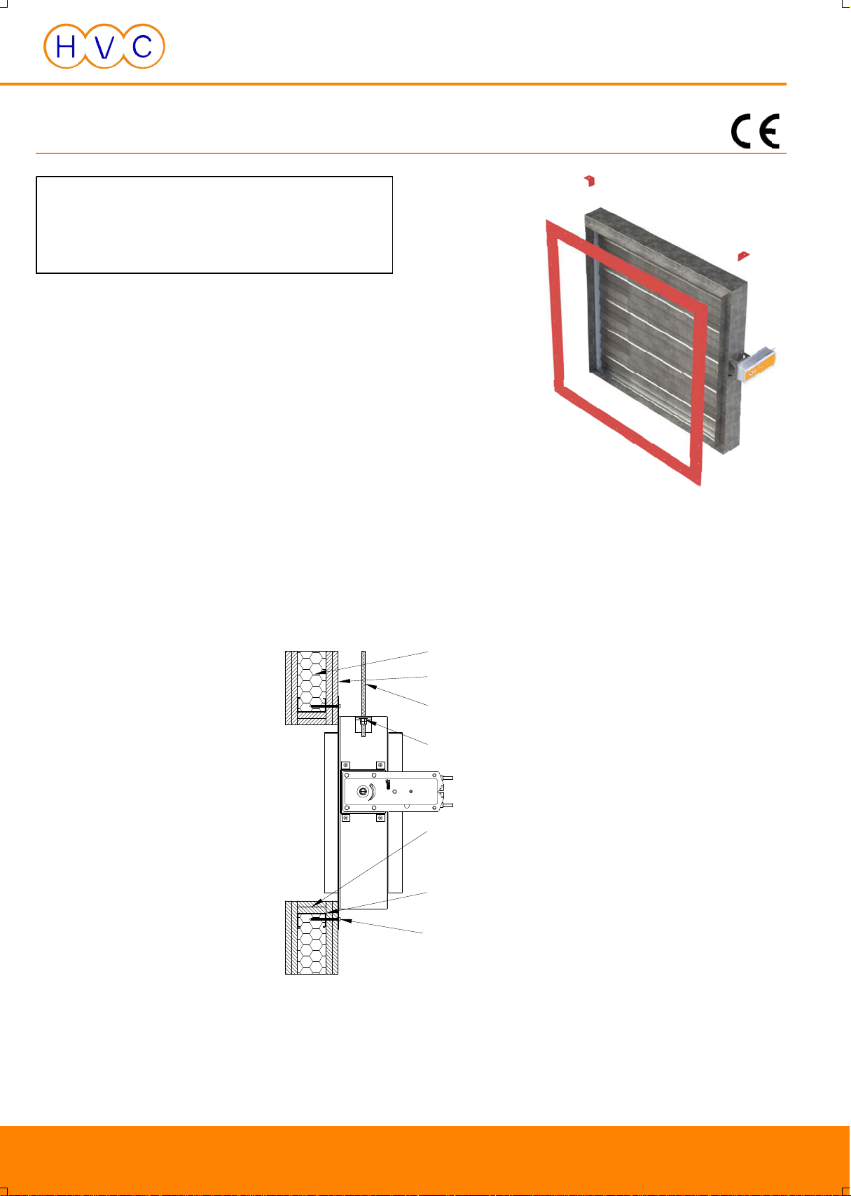
Uniquely easy to install, S700 fire dampers are surface mounted,
making use of fixing lugs and a simple plate frame with factory
punched fixing holes, installations require no backfilling, sealing or
pattress frames. This makes them especially useful for
refurbishment projects where disruption needs to be minimised.
S700 fire dampers are currently available with 120 minute rated
installations to suit drywall partitions, masonry walls and concrete
floor slabs (single sections only). All installations are classified ‘i↔o’
meaning air is permitted to flow in either direction through the
damper.
Actuators are Belimo BF series, are available in 24 or 230 volt
variants and are supplied with a 72°C rated thermal probe.
Design features
Materials Plate frame - 1.5mm galvanised steel
Case, internal frame and actuator mounting bracket - 1.2mm galvanised steel
Blades - 0.7mm galvanised steel (double layered)
Frame side, top and bottom seals - 0.4mm stainless steel (grade 301)
Drive system - Steel throughout (BZP coated)
Sizes Minimum: 200mm x 200mm / 200mm diameter nominal
Maximum: Single section - 1000mm x 1000mm / 1000mm diameter nominal
Multiple section - 2074mm x 2074mm / 2074mm diameter nominal
Units requiring a nominal width/height/diameter of less than 200mm can be supplied using reducing spigots
Operation Opposed blade, linkage driven (out of airstream)
Controls Single section assemblies: Belimo BF24-TN or BF230-TN actuator (power open, spring return, non-modulating)
complete with 72°C thermal probe
Multiple section assemblies: Belimo BF24 actuators (power open, spring return, non-modulating) complete with
relay box assembly (24V or 230V supply) with 72°C thermal probe
4

NCA Series 700
Motorised leakage rated fire dampers
Damper design
1. Plate frame
Serves as the mounting point for
fixing the damper to the partition.
Pre-punched 5mm diameter fixing
holes assist installation on site.
2. Fixing lugs
Mounted at the top of the case on
either side, these serve as
mounting points for hanging the
damper from either 8mm or 10mm
diameter threaded drop rods.
Fixing lugs are not required to be
used in horizontal applications.
3. Case
Comprises the spigots and
encapsulates the inner frame.
4. Inner frame
The main component around which
other components are fitted.
Formed bushes in the side
members hold steel tube axles to
which the blades are mounted.
5. Blades
Aerodynamic formed steel blades
designed to present low resistance
to airflow when open, but also to
provide the required strength and
level of shut-off when closed.
6. Stainless steel seals
Formed stainless steel seals sit
between the inside frame and
blade edges and ends.
7. Belimo BF series actuator
A specialist fire damper actuator
with integrated thermal probe,
powered open during normal use,
springs closed when required.
Positioned on damper’s left side
(as shown) unless specified.
1
2
3
7
4
5
6

www.h-v-c.com
NCA Series 700
Motorised leakage rated fire dampers
Blade leakage: Class 2 achieved
Tested unit size: 1000mm x 1000mm nominal
Product testing - Non-CE mandated
Case leakage: Class C achieved
Tested unit size: 1000mm x 1000mm nominal
Resistance to airflow
Tested unit size: 500mm x 500mm nominal
The blue line gives the resistance to airflow caused by the damper
Aerodynamic testing
S700 motorised leakage rated fire dampers have been tested for
blade leakage, case leakage and resistance to airflow in
accordance with:
BS EN 1751:2014
The testing was carried out in April and May 2019 by BSRIA in
Preston and Bracknell, England.
Copies of the test reports are available on request.
6

NCA Series 700
Motorised leakage rated fire dampers
Product testing - CE mandated
● BS EN 1366-2
Fire resistance test
Vertical installation in drywall partition: Tested for up to 120 minutes
Horizontal installation in aerated concrete floor slab: Tested for up to 240 minutes
● BS EN 13501-3
Classification of fire resistance performance
Classified to: E 120 (ve ho i ↔ o) S
Installation guide
HVC currently have three CE marked installations available for
Series 700 fire dampers.
Installation
code
Frame
type
Substrate Orientation
Nominal size range
(single sections,
w x h / dia, mm)
Nominal size range
(multiple sections,
w x h / dia, mm)
Classification
(EN 13501-3) Page/s
Drywall
partition
Masonry
wall
Concrete
slab Vertical Horizontal
S700-2VP/M
Plate
(P)
(M)
200 x 200* / 200*
to
1000 x 1000 / 1000
1001 x 1001 / 1001
to
2074 x 2074 / 2074
E 120 (ve i↔o) S 8 and 9
S700-2HC Not available E 120 (ho i↔o) S 10
* Units requiring a nominal width/height/diameter of less
than 200mm can be supplied using reducing spigots
7

www.h-v-c.com
NCA Series 700
Motorised leakage rated fire dampers
Installation S700-2VP
NCA Series 700 fire damper c/w plate frame in drywall partition
Installation procedure:
Hang the damper using the two factory fitted fixing lugs from drop rods
(M8/M10) securely attached to a structural element of the building
distinct from the partition itself.
Position the damper spigot (plate frame side) centrally within a correctly
sized aperture, constructed in accordance with our S700 installation
instructions.
Screw the damper to the wall through the factory punched fixing holes
in the plate frame, ensuring all screws gain a positive fix on the steel
framework inside the partition.
Fit the actuator’s thermal probe to the top half of ductwork.
No backfilling or sealing of the aperture, nor a pattress frame are
required.
The damper must be installed so blades run horizontally.
The above is a shortened version of our full installation method and does
not contain all details necessary to perform a compliant installation.
To download full installation instructions, declaration of performance and
maintenance routine, go to:
www.h-v-c.com/installations
Installation classified to (in accordance with BS EN 13501-3):
E 120 (ve i↔o) S
120 minute rated reduced leakage vertical installation
Air permitted to flow in either direction through damper
Permitted for single and multiple section assemblies
Wall cavity filled with mineral
wool
M8/M10 drop rods secured to
structural element of building
distinct from partition itself
M8/M10 washer and 2 qty bolts
locked off against each other
2 x 15mm thick plasterboard
sheets each side of steel stud
2 x 15mm thick plasterboard
strips lining aperture
Drywall screws
securing damper to partition
Steel frame forming aperture
8

NCA Series 700
Motorised leakage rated fire dampers
Installation S700-2VM
NCA Series 700 fire damper c/w plate frame in masonry wall
Installation procedure:
Open the factory punched 5mm diameter fixing holes in the plate frame
out to 8mm diameter.
Hang the damper using the two factory fitted fixing lugs from drop rods
(M8/M10) securely attached to a structural element of the building
distinct from the partition itself.
Position the damper spigot (plate frame side) centrally within a correctly
sized aperture, constructed in accordance with our S700 installation
instructions.
Screw the damper to the wall through the enlarged fixing holes in the
plate frame, ensuring all screws gain a positive fix on the masonry.
Fit the actuator’s thermal probe to the top half of ductwork.
No backfilling or sealing of the aperture, nor a pattress frame are
required.
The damper must be installed so blades run horizontally.
The above is a shortened version of our full installation method and does
not contain all details necessary to perform a compliant installation.
To download full installation instructions, declaration of performance and
maintenance routine, go to:
www.h-v-c.com/installations
Installation classified to (in accordance with BS EN 13501-3):
E 120 (ve i↔o) S
120 minute rated reduced leakage vertical installation
Air permitted to flow in either direction through damper
Permitted for single and multiple section assemblies
Masonry wall
M8/M10 drop rods secured to
structural element of building
distinct from partition itself
M8/M10 washer and 2 qty bolts
locked off against each other
Masonry screws
securing damper to partition
9

www.h-v-c.com
NCA Series 700
Motorised leakage rated fire dampers
Installation S700-2HC
NCA Series 700 fire damper c/w plate frame in aerated concrete floor slab
Installation procedure:
Position the damper spigot (plate frame side) centrally within a correctly
sized aperture, constructed in accordance with our S700 installation
instructions.
Open the factory punched 5mm diameter fixing holes in the plate frame
out to 8mm diameter, then screw the damper to the floor slab ensuring
all screws gain a positive fix.
Fit ductwork to damper spigots and then fit the actuator’s thermal probe
to ductwork.
Fixing lugs are redundant in this installation.
No backfilling or sealing of the aperture, nor a pattress frame are
required.
The above is a shortened version of our full installation method and does
not contain all details necessary to perform a compliant installation.
To download full installation instructions, declaration of performance and
maintenance routine, go to:
www.h-v-c.com/installations
Installation classified to (in accordance with BS EN 13501-3):
E 120 (ho i↔o) S
120 minute rated reduced leakage horizontal installation
Air permitted to flow in either direction through damper
Permitted for single section assemblies only
10
Concrete floor slab
Masonry screws
securing damper to slab

NCA Series 700
Motorised leakage rated fire dampers
Control panels
HVC are able to supply, install and commission a full range of fire
damper control panels to suit S700 fire dampers throughout the UK
and Republic of Ireland, including:
● Single/multiple zone electro-mechanical systems
● Basic addressable systems
● Fully addressable systems
For further information on control panels please contact HVC.
Separation between fire dampers and between fire dampers
and construction elements
● There should be a minimum of 200mm of supporting
construction between fire dampers installed in separate ducts.
● There should be a minimum of 75mm of supporting
construction between the fire damper and any adjacent
construction element, e.g. a wall or ceiling.
Further information: Direct field of application
11
Supporting construction
A test result obtained for a fire damper mounted in or on the face of
a standard supporting construction is applicable to a supporting
construction of the same type with a fire resistance equal to or
greater than that of the standard supporting construction used in the
test (thicker, denser, more layers of board etc.)

www.h-v-c.com
NCA Series 700
Motorised leakage rated fire dampers
Technical drawings
S700BGP
Square spigot (35mm deep)
Spigot 6mm under nominal (duct) width and height
Min nominal size: 200mm W x 200mm H
Max nominal size: 1000mm W x 1000mm H (single section)
2074mm W x 2074mm H (multiple section)
Please note: Units requiring a nominal width/height/diameter of less
than 200mm can be supplied using reducing spigots
This will increase damper depth by 70mm.
S700CGP
Circular spigot (40mm deep)
Spigot 3mm under nominal (duct) diameter
Min nominal size: 200mm dia.
Max nominal size: 1000mm dia. (single section)
2074mm dia. (multiple section)
Please note: Units requiring a nominal width/height/diameter of less
than 200mm can be supplied using reducing spigots
12

NCA Series 700
Motorised leakage rated fire dampers
Weight charts
S700DGP
Flat oval spigot (40mm deep)
Spigot 3mm under nominal (duct) width and
height
Min nominal size: 200mm W x 200mm H
Max nominal size: 1000mm W x 1000mm H
(single section)
2074mm W x 2074mm H
(multiple section)
Please note: Units requiring a nominal
width/height/diameter of less
than 200mm can be supplied using
reducing spigots
Nominal width (mm)
200 250 300 350 400 450 500 550 600 650 700 750 800 850 900 950 1000
Nominal
height
(mm)
200 10 11 11 12 13 13 14 15 15 16 17 17 18 19 19 20 21
271 12 12 13 14 14 15 16 17 17 18 19 20 20 21 22 22 23
371 13 14 15 16 16 17 18 19 20 20 21 22 23 23 24 25 26
471 15 16 17 17 18 19 20 21 22 23 23 24 25 26 27 28 28
571 16 17 18 19 20 21 22 23 24 25 26 27 27 28 29 30 31
671 18 19 20 21 22 23 24 25 26 27 28 29 30 31 32 33 34
771 20 21 22 23 24 25 26 27 28 29 30 31 32 33 34 35 37
871 21 22 24 25 26 27 28 29 30 31 32 34 35 36 37 38 39
971 23 24 25 26 28 29 30 31 32 34 35 36 37 38 39 41 42
1000 23 24 25 27 28 29 30 31 33 34 35 36 37 38 40 41 42
● Weights are in kg and include a Belimo BF actuator
● For multiple sections obtain total weight of component single
sections and add 10% to cover section joint cover plates.
Nominal diameter (m)
200 250 300 350 400 450 500 550 600 650 700 750 800 850 900 950 1000
12 14 17 18 21 23 26 27 31 33 36 38 42 44 48 50 52
13

www.h-v-c.com
NCA Series 700
Motorised leakage rated fire dampers
Single/multiple section assemblies
Single sections
Single section damper assemblies comprise a single damper
section complete with single actuator with integrated 72°C rated
thermal probe (Belimo BF24-TN or BF230-TN).
Multiple sections
Supplied factory assembled and comprising either two or four
dampers depending on the size required.
Each component section uses a single Belimo BF24 actuator which
is connected on site to a fire damper relay box.
Unique to HVC, fire damper relay boxes ensure that the component
single section dampers in a multiple section assembly operate in
unison while opening and closing.
Fire damper relay boxes power up to four actuators and are
equipped with a single thermal probe which should be fitted to
ductwork as normal. Relay boxes should be fitted to the partition or
floor, not ductwork.
PANEL WIRING
230v 50hz
5A FUSED
SUPPLY
FIELD WIRING
L
N
E
E
24v dc 2.5A POWER SUPPLY
L
NN
L
F1
6.3A
24v
0v
2
1ALTERNATIVE
24v dc SUPPLY
BAT 72
THERMAL FUSE
7
6
9
8
11
10
13
12
DAMPER
MOTOR 1
DAMPER
MOTOR 2
DAMPER
MOTOR 3
DAMPER
MOTOR 4
1
2
1
2
1
2
1
2
BELIMO MOTORS TYPE BF24
FIRE DAMPER RELAY BOX CIRCUIT DIAGRAM
14

NCA Series 700
Motorised leakage rated fire dampers
Installation should take into account the requirements of future
maintenance, with a view to providing adequate access to fire
dampers for testing and cleaning purposes.
We are able to supply a full range of access doors to facilitate
access into ductwork.
Installation into chlorinated environments
We are unable to supply S700 fire dampers suitable for installation
into chlorinated environments, swimming baths for example.
Any dampers installed into environments where chlorine is present
shall be considered to be installed in an unsuitable location and will
therefore not be covered by our standard 12 month warranty.
Installation
Maintenance of fire dampers is essential to ensure they remain in
good working condition for the life of the building.
An operation and maintenance manual for NCA Series 700 fire
dampers is available via:
www.h-v-c.com/oandm
Maintenance

www.h-v-c.com
NCA Series 700
Motorised leakage rated fire dampers
16
Finish
Bare metal only
Ordering codes
Codes
1) Quantity
2) Size (mm) (Width x height / diameter) Nominal size (see pages 12 and 13 for available sizes)
3) Series S700 Series 700 motorised leakage rated fire damper
4) Duct connection: B Square spigotted
C Circular spigotted
D Flat oval spigotted
Material: G Galvanised steel
Frame type: P Plate frame
6) Actuator/s: Single section damper assemblies only
BF24-TN Belimo BF series actuator c/w 72°C rated thermal probe, 24 volt
BF230-TN Belimo BF series actuator c/w 72°C rated thermal probe, 230 volt
Multiple section damper assemblies only
BF24 Belimo BF series actuator, 24 volt
Important: S700 fire dampers must be supplied with a factory fitted Belimo BF series actuator.
Actuators must always be used in a power open, spring return (fail closed) configuration with S700 fire dampers.
Single section dampers will be supplied with motors on their left side unless specified (as detailed in this brochure).
Multiple section dampers will be supplied with a relay box.
1 - 500 x 500 - S700BGP - BF24-TN
Example

NCA Series 700
Motorised leakage rated fire dampers
HVC & NCA products
HVC offer the significant advantage of manufacturing both in duct and
duct terminal equipment, making us a one stop shop for all your
HVAC needs.
The products shown below are a selection, not an exhaustive list. Go
to www.h-v-c.com for details on all HVC and NCA products.
HVC: Grilles, Diffusers, Louvres and Volume Control Dampers
NCA: Fire and volume control dampers
17

HVC Supplies (Stourbridge) Ltd
Jason House
Amblecote
West Midlands
DY8 4EY
United Kingdom
Tel: +44 (0)1384 376555
Fax: +44 (0)1384 392555
www.h-v-c.com
Assessed to ISO 9001
Cert/Ref No. 1186
All details within this brochure are correct at
time of publication. However HVC’s policy is
one of continual product development. The right
is reserved to alter any details published in this
brochure without any prior notice. Any changes
will appear on www.h-v-c.com as soon as is
practically possible.
All information in this brochure is designed to
be used for informative purposes only. HVC will
not be legally bound by anything contained
within this publication, or any other information
distributed.
All references to companies not part of the HVC
group of companies are used with the
permission of their respective owners.
Other manuals for NCA 700 Series
1
This manual suits for next models
3
Table of contents
Other HVC Fire And Smoke Damper manuals
Popular Fire And Smoke Damper manuals by other brands

Greenheck
Greenheck EHM-601 Installation, operation and maintenance manual

SIOX
SIOX MIDI SMOKE 2 manual

KOOLAIR
KOOLAIR CEVH Mounting instructions

klimaoprema
klimaoprema RKP-P-N product manual

Trox Technik
Trox Technik FKRS-EU Installation and operating manual

Advanced Air
Advanced Air 0160 Series quick start guide