www.h-v-c.com
Installation guide
NCA Series 400 single blade leakage rated fire damper c/w plate frame
Prior to installation
• Thermal links/probes in particular are vulnerable to damage, take extreme care if storing smaller
dampers within larger dampers. Damaged links/probes must be replaced.
• If damper is to be stored on site, ensure it is stored in a clean and dry environment.
• Immediately prior to fitment, remove all packaging from the unit. Take particular care inspecting
the inside of the unit for any packing materials which may disrupt damper operation.
• Perform a visual check of the damper to ensure it is free from damage.
Installation
• Fire damper installation should only be carried out by competent persons.
• Appropriate PPE should be used throughout the installation.
• Provision for access to both sides of the damper (inside the duct) must be made.
• Any cabling should be tied back so as not to be in contact with the duct.
• Breakaway joints should be used where ductwork connects to a damper spigot, for example
through the use of aluminium rivets.
• Case sealing rings should be lubricated to ease ductwork connection, for example with a
sprayed washing-up liquid solution or similar.
Installation guide: NCA Series 400 leakage rated single blade fire damper c/w plate frame
Approved installation method, operation and installation declaration
Page 1 of 2 - Issue A - 16/03/2022
Installation classified to (in accordance with BS EN 13501-3):
E 120 (ve i↔o) S
120 minute rated reduced leakage vertical installation
Air permitted to flow in either direction through damper
Installation S400-2VP
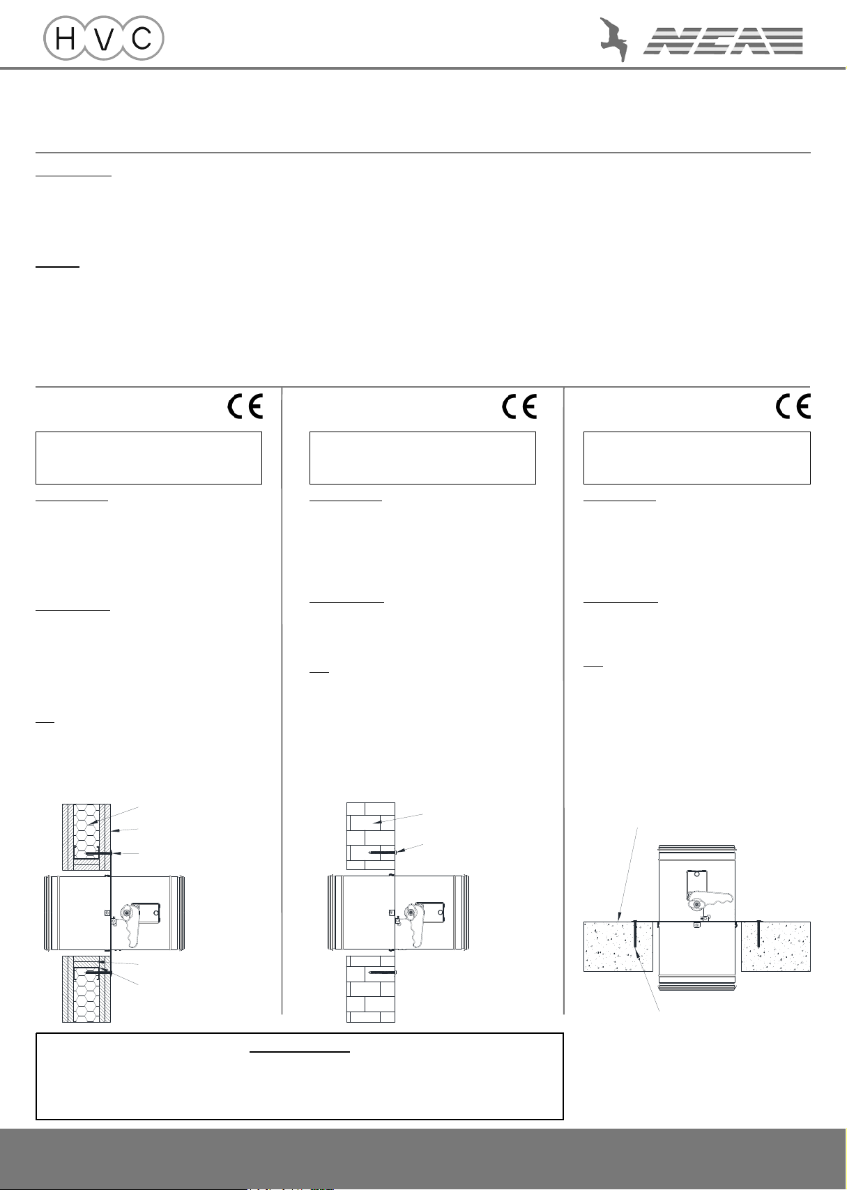
Drywall partition installation
Installation procedure
• Construct drywall partition steel frame incorporating a rectangular
aperture for the damper 94mm larger than damper nominal size.
• Fill wall cavity with mineral wool (optional, see note below) and fix two
layers of plasterboard to both sides of partition and inside of aperture
(lined aperture should be 34mm larger than damper nominal size).
• Centralise damper spigot within aperture.
• Screw damper to partition using all pre-cut 5mm holes in plate
frame, ensure all screws gain a positive fix on the steel aperture frame.
• S400A only - Fit thermal probe to top half of ductwork and connect
actuator to an appropriate power supply.
Material specifications
Wall: Constructed to achieve ‘EI 120’ classification
(or greater) in accordance with EN 1363-1
Minimum thickness 122mm
Stud depth: 62 - 100mm
Plasterboard: EN 520 F rated, 15mm thick
‘Gyproc Fireline’, ‘Knauf DF’ or equivalent
Mineral wool: Minimum density 100kg/m3
Minimum thickness 60mm
‘Rockwool RW5’ or equivalent
Fixing screws: Minimum spec 4.2mm x 65mm drywall screws
Notes
• No backfilling, sealing or pattress frame is required.
• The blade axis must be horizontal.
• The steel aperture frame must be joined to vertical frame members
which are themselves fixed to the supporting construction.
• Mineral wool infill is optional (as per EN 1366-2:2015, clause 13.7).
Installation S400-2VM
Masonry wall installation
Installation procedure
• Construct wall incorporating a square or circular aperture for the
damper 34mm larger than damper nominal size.
• Open the pre-cut 5mm diameter fixing holes in the plate frame out to
8mm.
• Centralise damper spigot within aperture.
• Screw damper to wall using all 8mm holes in plate frame, ensure all
screws gain a positive fix.
• S400A only - Fit thermal probe to top half of ductwork and connect
actuator to an appropriate power supply.
Material specifications
Wall: Constructed to achieve an equivalent or greater fire
resistance as a drywall partition of ‘EI 120’
classification in accordance with EN 1363-1
Minimum thickness 130mm
Fixing screws: Minimum spec 6mm x 60mm masonry screws
Notes
• No backfilling, sealing or pattress frame is required.
• The blade axis must be horizontal.
Installation S400-2HC
Concrete floor installation
Installation procedure
• Construct floor slab incorporating a square or circular aperture for the
damper 34mm larger than damper nominal size.
• Open the pre-cut 5mm diameter fixing holes in the plate frame out to
8mm.
• Centralise damper spigot within aperture.
• Screw damper to slab using all 8mm holes in plate frame, ensure all
screws gain a positive fix.
• S400A only - Fit thermal probe to ductwork and connect actuator to an
appropriate power supply.
Material specifications
Floor: Concrete slab (aerated or normal)
Minimum thickness 150mm
Minimum density 600kg/m3
Fixing screws: Minimum spec 6mm x 60mm masonry screws.
Notes
• No backfilling, sealing or pattress frame is required.
• The damper must sit on top of the floor, not be hung from below.
IMPORTANT NOTE
It is a legal requirement that fire dampers are installed in the way instructed by the manufacturer.
Any other installation is untested and therefore illegal.
Responsibility for ensuring correct installation lies with all parties in the supply chain.
Installation classified to (in accordance with BS EN 13501-3):
E 120 (ve i↔o) S
120 minute rated reduced leakage vertical installation
Air permitted to flow in either direction through damper
Installation classified to (in accordance with BS EN 13501-3):
E 120 (ho i↔o) S
120 minute rated reduced leakage horizontal installation
Air permitted to flow in either direction through damper
• There should be a minimum of 200mm of supporting construction between fire dampers
installed in separate ducts.
• There should be a minimum of 75mm of supporting construction between the fire damper
and any adjacent construction element, e.g. a wall or ceiling.
Where a damper is fitted such that the actuator shall be next to a wall, this should be increased
to 200mm to provide adequate clearance.
• An increase of the gap (area) between the damper and supporting construction of up to 50%
is permitted (as per EXAP report, EN 15882-2:2015, clause X.45).
• A decrease of the gap (area) between the damper and supporting construction is permitted
(as per EXAP report, EN 15882-2:2015, clause X.46).
Recommended spares: S400H - Thermal link in correct temperature rating
68°C (red bulb in link) or 93°C (green bulb in link)
S400A - Thermal probe tripping element - ‘Belimo ZBAT72’
Installation declaration overleaf →
Wall cavity filled with mineral wool
(optional)
2 x 15mm thick plasterboard
sheets each side of steel stud
2 x 15mm thick plasterboard strips
lining aperture
Drywall screws
securing damper to partition
Steel frame forming aperture
Masonry wall
Masonry screws
securing damper to partition
Concrete floor slab
Masonry screws
securing damper to slab