Hwayuan Electric NB-250/315LT User manual

NB-250/315LT
MIG WELDING MACHINE
MANUAL
INSTRUCTION
(PLEASE READ CAREFULLY BEFORE OPERATION

Safety Depends on You
Huayuan arc welding and cutting equipments are designed and built with safety in mind. However, your overall safety can be increased by
proper installation.
DO NOT INSTALL, OPERATE OR REPAIR THIS EQUIPMENT WITHOUT READING THIS MANUAL AND THE SAFETY PRECAUTIONS CONTAINED
THROUGHOUT. And, most importantly, think before you act and be careful.
Special Attention (Very Important):
●AVOID FALLING DOWN WHEN THE WELDING MACHINE IS PLACED ON THE INCLINED PLANE.
●IT’S CAN NOT BE USED FOR UNFREEZING PIPELINES.
●THE SHIELD RANK OF THIS SERIES OF WELDING MACHINE IS IP21S, AND IT IS NOT SUTABLE FOR WORKING IN THE RAIN.
Purchase Date:
Serial Number:
Machine Type:
Purchase Place:

C a u ti o n s
Arc and arc rays may harm health.
Arc welding can be hazardous. All performing welding workers ought to have health qualification that provided by authority
organization. Protect yourself and others from possible serious injury or death. Keep children away. Pacemaker wearers should consult
with their doctor before operating. Be sure that all installation, operation, maintenance and repair procedures are performed only by
qualified individuals.
1Electric shock can kill: The electrode and work (or ground) circuits are electrically “hot” when the welder is on.
Do not touch these “hot” parts with your bare skin or wet clothing, Wear dry, hole-free gloves to insulate hands.
Users need to follow the below items to avoid electric shocks:
Insulate yourself from work and ground using dry insulation. Make certain the insulation is large enough to cover your full area of
physical contact with work and ground. Otherwise, use automatic or semiautomatic welding machines, DC welding machines as
possible as you can.
In semiautomatic or automatic wire welding, the electrode,electrode reel, welding head, nozzle or semiautomatic welding gun are
also electrically“hot”.
Always be sure the work cable makes a good electricalconnection with the metal being welded. The connection should be as close
as possible to the area being welded.
Ground the work or metal to be welded to a good electrical(earth) ground.
Maintain the electrode holder, work clamp, welding cable and welding machine in good, safe operating condition. Replace
damaged insulation.
Never dip the electrode in water for cooling.
Never simultaneously touch electrically“hot”parts of electrode holders connected to two welders, because voltage between the
two can be the total of the open circuit voltage of both welders.
When working above floor level, please do wear safety belt to avoid falling or losing balance on electric shock.
2Arc rays can burn: Use a shield with the proper filter and cover plates to protect your eyes from sparks and the
rays of the arc when welding or observing open arc welding. Headshield and filter lens should conform to nation
standards.
Use suitable clothing made from durable flame-resistant material to protect your skin and that of your helpers from the arc rays.
Protect other nearby personnel with suitable, non-flammable screening and/or warn them not to watch the arc nor expose
themselves to the arc rays or to hot spatter or metal.
3Fumes and Gases can be dangerous: Welding may produce fumes and gases hazardous to health. Avoid
breathing these fumes and gases. While working in limited room, use enough ventilation and/or exhaust to keep
fumes and gases away from the breathing zone, or use the respirator.
Shielding gases used for arc welding can displace air and cause injury or death. Always use enough ventilation,especially in
confined areas, to insure breathing air is safe.
Do not weld in locations near chlorinated hydrocarbon vapors coming from degreasing, cleaning or spraying operations.The heat
and rays of the arc can react with solvent vapors to form phosgene, a highly toxic gas, and other irritating products.
Read and understand the manufacturer’s instructions for this equipment and the consumables to be used, including the material
safety data sheet (MSDS) and follow your employer’s safety practices. Make sure they are asepsis and innocuity.
4Spatter: Welding or cutting spatter can cause fire or explosion.
Remove fire hazards from the welding area.If this is not possible, cover them to prevent the welding sparks from
starting a fire. Remember that welding sparks and hot materials from welding can easily go through small cracks

and openings to adjacent areas. Avoid welding near hydraulic lines. Have a fire extinguisher readily available.
Where compressed gases are to be used in the field, special precautions should be used to prevent explosion.
When not welding, make certain that no electriferous part is touching the work piece or the work stage. Accidental contact can
create a fire hazard.
Do not weld containers or lines, which are not proved to be innocuity.
Do not heat, cut or weld tanks, drums or containers until the proper steps have been taken to insure that such procedures will not
cause flammable or toxic vapors from substances inside. They can cause an explosion even though they have been“cleaned”.
Spatter might cause burn. Wear leather gloves, heavy shirt, cuffless trousers, high shoes and a cap over your hair to prevent from
burning by spatter. Wear the ear shield when performing sideways or face up welding. Always wear safety glasses with side
shields when being in a welding area.
The welding cables should be as close to the welding area as possible, and the short, the better. Avoid welding cables going
through the building framework, lifting chains, AC or DC cables of other welding machines and appliances. The welding current is
strong enough to damage them while having short circuit with them.
5Cylinder may explode if damaged.
Make sure that the gas in the storage cylinder is qualified for welding, and the decompression flowmeter, the
adapter and the pipe are all in good condition.
Always keep cylinders in an upright position securely chained to an undercarriage or fixed support.
Be sure to put the cylinder in the working space with no crash or shake, and far from welding area.
Never allow the electrode, electrode holder or any other electrically“hot”parts to touch a cylinder.
Keep your head and face away from the cylinder valve outlet when opening the cylinder valve.
Valve protection caps should always be in place and hand tight except when the cylinder is in use or connected for use.
6Power: (For electrically powered welding and cutting equipment) Turn off input power before installation,
maintenance and repair to avoid accidents.
Huanyuan welding equipment is Ι class safeguard equipment; please install the equipment in accordance with
the manufacturer’s recommendations by specific persons.
Ground the equipment perfectly in accordance with the manufacturer’s recommendations.
7Power:(For engine driven welding and cutting equipment)
Work in ventilated place or outdoors.
Do not add fuel near to fire or during engine starting or welding. When not working, add fuel after engine is
cooling down; otherwise, the evaporation of hot fuel would result in dangers. Do not splash fuel out of the fuel
tank, and do not start the engine until complete evaporation of the outside fuel.
Make sure that all the safeguard equipments, machine cover and devices are all in a good condition. Be sure that
arms, clothes and all the tools do not touch all the moving and rotating components including V belt, gear and fan
etc.
Sometimes some parts of the equipment have to be dismantled during maintenance, but you still have to keep the strongest
safety awareness .
Do not put your hand close to fans and do not move the brake handle while operating.
Please remove the connection between the engine and the welding equipment to avoid sudden starting during maintenances.
When engine is hot, it is forbidden to open the airtight cover of the radiator water tank to avoid hurt by the hot vapor.
8Electromagnetic: Welding current going though any area can generate electromagnetic, as well as the welding
equipment itself.
Electromagnetic would affect cardiac pacemaker, the cardiac pacemaker users should consult one’s doctor first.
The effect of electromagnetic to one’s health is not confirmed, and it might have some negative effect to one’s health.
Welders may use following method to reduce the hazardous of electromagnetic:

a. Bundle the cable connected to the work piece and the welding cable together.
b. Do not enwind partially or entirely your body with the cable.
c. Do not place yourself between the welding cable and the ground (work piece) cable, if the welding cable is by your left side,
then the ground cable should be by your left side too.
d. The Welding cable and the ground cable are as short as possible.
e. D e. Do not work near to the welding power source.
9Lifting equipment: carton or wooden boxes package the welding machines supplied by Huayuan. There is no
lifting equipment in its wrapper. Users can move it to the prospective area by a fork-lift truck, then open the
box.
If there are rings, the machine can be transited by rings. While Huayuan Welding Machine Manufacture reminds
users, there is potential risk to damage the welding machine. So it is better to push the welding machine by its
rollers unless special situations.
Be sure that the appurtenances are all removed off when lifting.
When lifting, make sure that there is no person below the welding machine, and remind people passing by at any
moment.
Do not move the hoist too fast.
10 Noise: Huayuan Welding Machine Manufacture reminds users: Noise beyond the limit (over 80 db) can cause
injury to vision, heart and audition depending on oneself. Please consult local medical institution. Use the
equipment after doctor’s permission would help to keep healthy.

CONTENT
1 Summary ........................................................................................................................................
1
1.1 Model introduction ..............................................................................................................................1
1.2 Features .............................................................................................................................................. 1
1.3 Usage .................................................................................................................................................. 1
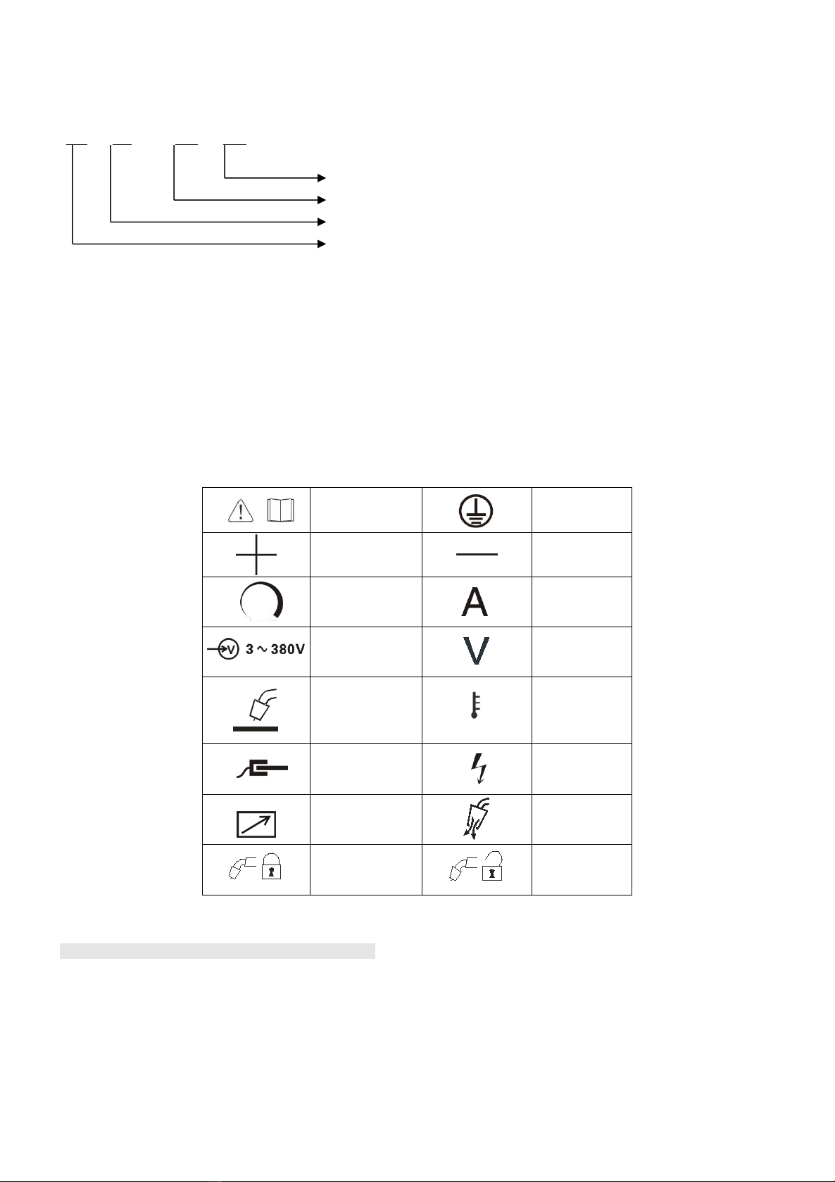
1.4 Symbols Introduction ........................................................................................................................... 1
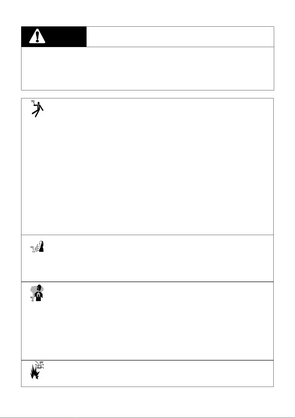
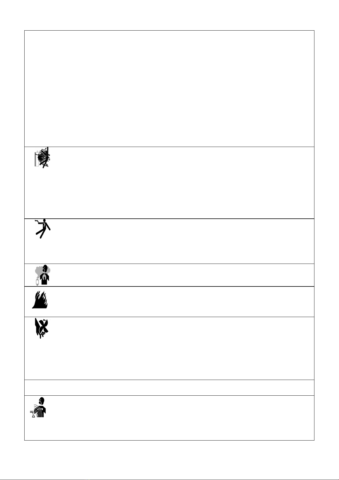
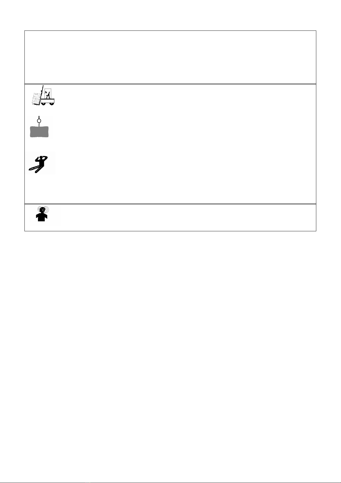
1.5 Safety attentions ..................................................................................................................................1
2 Working condition and environment ...............................................................................................
2
2.1 Operation place ................................................................................................................................... 2
2.2 Power supply .......................................................................................................................................2
3 Technical Parameters ......................................................................................................................
2
4 Products system introduction ..........................................................................................................
3
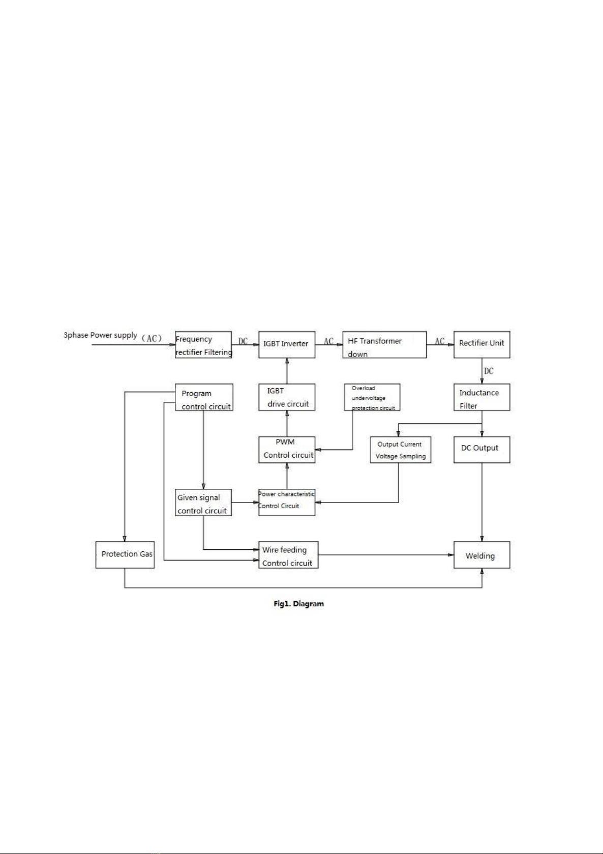
4.1 Summarize of working principles ..........................................................................................................3
4.2 Main electric diagram .......................................................................................................................... 3
4.3 Block schematic diagram ......................................................................................................................3
5 Panel function introduction .............................................................................................................
4
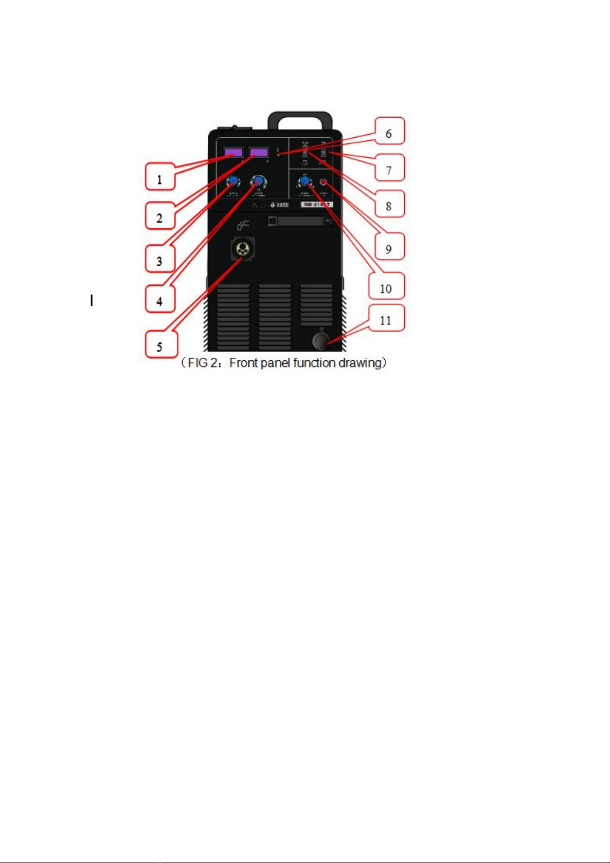
5.1 Front Panel function drawing ............................................................................................................... 4
5.2 Rear Panel Function Drawing ................................................................................................................5
Gas bottle bracket(Optional)introduction and installation drawing ............................................................. 5
6 Installation .....................................................................................................................................
7
6.1 Power supply: ...................................................................................................................................... 7
6.2 Installation (please refer to figure 8) .....................................................................................................7
7 Operation .......................................................................................................................................
7
7.1 Operating instructions ..........................................................................................................................7
7.2 Matters need attention ........................................................................................................................ 8
8 Maintenance and repairing .............................................................................................................
9
8.1 Matters need attention ........................................................................................................................ 9
8.2 Maintenance ....................................................................................................................................... 9
8.3 Trouble shooting ..................................................................................................................................9
8.4 Main parts list ..................................................................................................................................10
9 Packing list ..................................................................................................................................
13
10 Drawing ....................................................................................................................................
14

1
1 Summary
1.1 Model introduction
N B — □□□ LT
Product series
Rated welding current(A)
Semi-automatic welding
Gas shield welding machine
1.2 Features
Striking arc under high voltage and slow wire feed. Smooth and stable arc striking with high success rate;
Adopting unique feedback control circuit of arc voltage and current, stable welding process, little spatter, strong adaptability of
wire extension change, wide adjusting range for matching current and voltage, well-shape weld appearance;
Adopting high performance ball-eliminating circuit, the diameter of ball on wire end almost the same as wire diameter, high
success rate at arc striking;
1.3 Usage
Widely applied in the fields of automobile, steel furniture, filing cabinet, security door, guard railing, and building decoration, suitable
for all position welding on the mild carbon steel in thickness 0.8~6mm;
Ф0.8、Ф1.0 solidwire is suitable.
1.4 Symbols Introduction
Please read
manual
Connect earth
cable
Positive
negative
Up/down
current
Input voltage
voltage
MIG/MAG
Over heat
Connection with
workpiece
Dangerous
voltage
Remote control
Clear air
(check-air)
Self-lock
non self-lock
1.5 Safety attentions
To you and others safety, please do abide by the below items:
The welding machine should be grounded reliably:
To prevent electric shock, please do ground the green-yellow wire well;
Wear protective equipments
To prevent the hurt of welding gas, dust, arc, spatter and noise, please do wear some protective equipments and install necessary
ventilation devices. Keep kids away from the dangerous area;

2
The cylinder of shielding gas should be fixed well to ensure there is no shock;
Welding machines and procedure should be away from combustible and explosive material,do not weld closed container. It is
dangerous to weld the hand-hole of container,please make sure there is no combustible and toxic gas on the weld before
operation;
Keep sharp objects and other wastes away from the inner machine;
If dropping or cracking, the welding machine can not be used again without checking by qualified individuals.
2 Working condition and environment
2.1 Operation place
If machine is not operated according to the below items, the welding performance should be poor even damage the machine!
The machine should be placed in where there is no sunshine shooting, rain, dust, etchant gas and combustibles, the environment
temperature is to be in the range of -10℃~40℃.
The machine should be placed in where there is no metal waste;
Keep the welding power source away from wall or other closed objects at least 30cm, the distance between two welding
machine is also said to more than 30cm;
Operate this machine in where there is no wind.
Operate this machine in where the altitude is lower than 1000m.
2.2 Power supply
Power:3~50Hz380VAC
Fluctuation range of distribution voltage:<±15%
Fluctuation range of frequency:<±1%
Unbalance ratio of three phase voltage:<±5%
When engine generator is used: make sure the output power of the generator is 2 times larger than the rated input power of
welding power source, compensating coil is also needed.
3 Technical Parameters
Item
Unit
Model
NB-250LT
NB-315LT
Input power
V/Hz
3~380/415V 50/60Hz
Rated input capacity
KVA
10.3
14.6
Rated input current
A
15.7
22.1
rated output current
A
250
315
rated output voltage
V
26.5
29.8
Rated open voltage
V
64
Duty rated
-
35%(40℃)
efficiency
-
85%
86%
efficiency factor
-
0.74
0.75
Output Voltage
adjustment
V
15~32
Wire feeding speed
m/min
1.5~28
Suited wire diameter
mm
Φ0.8、Φ1.0
Cooling mode
-
Air cooling
Insulation grade
-
F
Ingress protection
-
IP21S
Dimension(L×W×H)
mm
640×300×595
Power net weight
kg
38
39

3
The static external characteristic of this machine is dropping characteristic, it`s rated duty cycle is 35%, which means in a 10
minutes work cycle, the welding machine can work 3.5 minutes(stop 6.5 minutes) under the rated current. If it is forced to use over the
rated duty cycle, the inner temperature will exceed the set temperature. To avoid poor working or burning, a overheating protection
function is set: when overheating, the indicator light lights and there is no outputing from the welding machine, it can work again after the
temperature dropping.
When welding current is lower than 200A, the gas flow is 8-15L/min, when the welding current is larger than 200A, the gas flow is
15-25L/min.
4 Products system introduction
4.1 Summarize of working principles
This series of CO2/MIG/MAG inverter gas shield welding machine adopts the latest electron device----IGBT is the key inverter device.
The three phase AC power is transformer into 20KHz high frequency voltage after bridge rectified. The high frequency voltage output
welding voltage after transforming, rectifying and filtering.
4.2 Main electric diagram
Please refer to the attached figure
4.3 Block schematic diagram

4
5 Panel function introduction
5.1 Front Panel function drawing
Function of figures 2 as below:
1. Digital display meter of voltage:when machine is not working, it display preset voltage, when machine is working, it display the
actual welding voltage;
2. Digital display meter of current:to display the actual welding current;
3. Adjusting knob of welding voltage: to adjust the welding voltage;
4. Adjusting knob of welding current: to adjust the welding current;
5. Plug seat of welding torch: plug of welding torch, Europe type interface;
6. Over heating indicator light: when the welding machine is working in high temperature environment and working overload, the
temperature of radiator is higher than 75℃±5℃, the protection circuit begin to work, and then output current will be cut. At the same
time, the cooling fan go on working, after the temperature get down, the welding machine will work normal again. The indicator light
will also light when the air flue jammed or cooling fan damaged.
7. Change-over switch of welding & gas checking: before welding, to adjust the shield gas flow, turn it on "gas checking". Turn it on
"welding" position when welding.
8. Change-over switch of self-lock & non-lock: when it is put on"self-lock", press the torch button and then the arc can be stroke,
loosen the button, welding will keep on normally, press the button again, welding finishes. When it is put on "non-lock", press the
button, welding begins, loosen the button, welding finishes.
9. Manual wire feeding button: press it and the wire feeder work. Wire feeding speed can be adjusted by welding current. When wire
diameter is small, the wire feeding speed should be slow to prevent bending the wire.
10. Arc characteristic adjust knob: Gas welding,use to adjust and control the different period current rate of melting drop process,
adjust the knob directly affect the arc soft/hard,spatter,welding shape and arc stability.Recommend use standard characteristic.
Note:large spatter if arc hard,otherwise small.
11. -(power output negative): use to connect the earth cable;

5
5.2 Rear Panel Function Drawing
1) Input cable of three phase power: connect to distribution box, connect the green-yellow wire to ground wire reliably;
2) Heater power source interface:Heater connector,output voltage 36VAC;
3) Wire feeding fuse holder:Used for short connect and over current protection of Wire feeder power supply circuit,inside Fuse
8A;
4) Control fuse holder:used for short connect protection of welding machine control circuit,inside fuse 1.5A;
5) Over current protection switch(Air switch):welding machine have abnormal,disconnect the power source then protect.The
switch only for protection,another power switch shall be configured during installation welding machine.
6) Cooling fan: To cool power source;
Gas bottle bracket(Optional)introduction and installation drawing
1) Gas bottle bracket parts introduction as FIG4:
(FIG 4 Gas bottle bracket part drawing)
Note: Gas bottle bracket is the optional!!!
2) Gas bottle installation drawing:
U-Style
bracket
Support
plate
Support
plate

6
(FIG 5 Gas bottle bracket installation drawing)
(FIG 6 Gas bottle U-Style bracket installation drawing)
Note: if buy gas bottle bracket together machine,please remove the two rear wheels and install them on the support plate of bracket,Then
install U-stype bracket and done,refer to Fig 5 and 6.
Fig 7 is the comparison for the welding
machine which with and without bracket.
standard Power source Power source with gas bottle bracket(Optional)
(FIG 7)
M8 screw
(18pcs)
M6 screw
(6pcs)

7
6 Installation
6.1 Power supply:
Specification
NB-250/270LT
NB-315LT
Capacity of power supply switch(A)
25
32
Capacity of fuse (A)
23
30
Sectional area of power supply line (mm2)
≥2.5
≥2.5
Sectional area of ground wire(mm2)
≥4
≥4
6.2 Installation (please refer to figure 8)
Make sure the distribution switch is cut down, and then connect the welding machine. Do not operate with wet hands. Do not
put anything on the power cable. Connect all the parts well. Install according to the below orders:
Connect the three phase power cable to the power switch of distribution box well, the green-yellow line of welding machine
should be reliably connected with ground wire in the distribution box.
Connect the quick coupling of ground wire with the socket of workpiece, tighten it by clockwise, connect the other end of
ground wire with workpiece reliably.
Insert the plug of torch into socket, fasten the ring nut and tighten the torch.
Install the CO2pressure flow regulator on the gas cylinder, fasten the nuts;
Connect the plug of CO2pressure flow regulator heater to the socket in the back panel;
Connect the φ8 gas line to the output air cock of CO2pressure flow regulator, and connect the other end of gas line to input air
cock, clamp it with hoop. Please use standard shield gas, or there will be welding defect.
7 Operation
7.1 Operating instructions
A. Installation of electrode wire (see figure 9 as reference)
Open up the left upper panel of welding machine, stand the panel on it;
Adjust the catch of electrode wire reel, the stretch out direction of catch should be same as the axis direction of wire reel shaft,

8
put wire reel on the shaft. Adjust the catch of electrode wire reel, the stretch out direction of catch should be vertical with axis
direction of wire reel shaft, fast it to prevent rolling out.
Make sure the wire slot diameter of wire feeding wheel is same as the electrode wire diameter;
Loosen the clamp handle of wire feeder, put up the wire wheel, pull out the wire tip, cut off the deformation part, insert the
wire tip into the wire guide pipe, it reach torch connector through guide tube, press the wire wheel and fasten it with suitable
strength;
B. Make sure the diameter of contact tip is same as the used electrode wire;
C. Put three phase switch on, press the button of "Manual wire feed", adjust welding current to get suitable wire feeding speed,
loosen the button till 15---20mm electrode wire is sticked out.
D. Put the switch of "welding/gas checking" on "gas checking" position, unscrew the switch of gas cylinder with a suitable speed till
get the wanted gas flow value, and then put the switch on "welding" position;
E. Adjust the button of "welding current" by actual needed current;
F. If welding current is confirmed, the welding voltage can be figured out by the formula of U (welding voltage )=14 +
0.05×I(welding current), adjust the button of "welding voltage" and make it displayed on digital meter;
G. Change-over switch of self-lock & non-lock: when it is put on"self-lock", press the torch button and then the arc can be stroke,
loosen the button, welding will keep on normally, press the button again, welding finishes. When it is put on "non-lock", press
the button, welding begins, loosen the button, welding finishes;
H. After finishing the above adjustment, wear required safety equipments, then normal welding process can be operated;
I. To get excellent welding performance, the "welding current" and "welding voltage" should be adjusted when welding.
7.2 Matters need attention
A. When welding, the cable of welding torch can not be bended too much, or it will affect normal wire feeding;
B. Lubricating grease or engine oil can not be used on wire feeding roll and wheel;
C. The contact tip of welding torch is consumable, after long time use, the welding current may unstable, please replace it in time;
D. The nozzle of welding torch is consumable, please replace it in time. When clear the spatter on nozzle, please take it down and
clear lightly. A spatter prevent grease is recommended to use, which can clear spatter easily and lengthen the service life of
nozzle.
E. After long time use, dust get into the wire feeding pipe of welding torch, which may affect normal welding, so please take the
pipe out at fixed period and wash with kerosene or dry compressed air, shake the pipe before cleaning;
F. When welding, please control the wire length between nozzle and workpiece. Generally, the length should be 10 times as wire
diameter; If too long, there will be unstable welding current, more spatter and air hole; if too short, the nozzle will be easily
blocked by spatter;

9
8 Maintenance and repairing
8.1 Matters need attention
A. When maintain or repair, the power must be cut off.
B. Since this machine is filtered by large capacity and high voltage electrolytic capacitor, it can not be opened and repaired in 5
minutes after cutting off power.
8.2 Maintenance
A. Check connectors at fixed period to see if they become flexible or if there is poor contact;
B. Keep machine clean: the service life will be shorten because of dirty in the machine, so please open and clean the machine at
least half a year;
8.3 Trouble shooting
A. The three phase voltage should be 380±15%, check and make sure the voltage is in this range;
B. Make sure the power switch is not damaged, and the fuse and power cable are installed reliably, or there may be open phase or
poor contact;
C. Make sure the connection of welding cable is good.
D. Check if welding switch or cable is damaged, and if nozzle, contact tip, tip table and shunt are burned or damaged;
Common faults and eliminating methods:(see below sheet)
Faults
Reasons
Eliminating methods
1.Put power on, the
power indicator do not
light
1.Open phase of three phase
power;
2.The power switch is old and
damaged;
3.The 1.5A fuse of power
control is melt;
1.Check the three phase power switch;
2.Replace power switch;
3.Replace the fuse;
2.Welding machine do
not work, under
voltage indicator light
1.Open phase on three phase
power;
2.Under voltage on three
phase power;
Check three phase supply power, make
sure supply voltage fit the required
voltage;
3.Press torch switch,
wire wheel moves, but
there is no wire
sending out from
torch, or the wire
feeding is unstable
1.The wire wheel is not tighten;
2.The diameter of wire slot is
not same as electrode wire;
3.The contact tip is blocked by
spatter;
4.The wire reel slog is abraded;
5.The wire feeding pipe of
torch is blocked;
6.The torch cable is excessive
bended;
1.Fasten the wire wheel;
2.Replace wire slot;
3.Eliminate the spatter on contact tip;
4.Replace wire feeding wheel;
5.Clean the dirty or dust in wire feeding
pipe by dry compressed air or replace it
with a new one;
6.Make the bending diameter of torch
cable larger than 300mm;
4.Welding machine do
not work, the over
heating indicator lights
1.The environment
temperature is too high;
2.There is something wrong
with the cooling fan;
3.The temperature relay is
damaged;
1.Make welding machine rest for a
moment;
2.Check the power of cooling fan or
replace cooling fan;
3.Replace the temperature relay;
5.The gas heater frosts
1.Poor contact on heater plug
seat;
2.Open circuit on heater
resistance wire;
1.Check the plug and socket of heater;
2.Repair or replace heater;
6.Press torch switch,
the wire feeding wheel
do not move or there is
no welding current
1.Open circuit on welding torch
cable;
2.The wire feeding motor is
damaged;
3.The PCB is damaged;
1.Check the control cable of welding
torch;
2.Repair the wire feeding motor or replace
it with a new one;
3.Repair or replace PCB;

10
7.There are too many
air holes on welding
seam;
1.CO2gas is not pure;
2.The gas flow is not enough;
3.There is grease dirt or rust on
welding seam;
4.The wind in the welding place
is too heavy;
5.CO2gas circuit is blocked or
blab;
6.Gas valve doen`t actuate;
7.Deformation on nozzle;
1.Use high purity CO2gas;
2.Adjust the gas flow;
3.Eliminate the grease dirt or rust on
welding seam;
4.Do something to reduce the wind in
welding place;
5.Check the gas circuit, dredge it or block
it;
6.Replace the nozzle of welding torch;
8.There is too much
spatter or the welding
current is not stable
1.Open circuit on three phase
power;
2.Wrong welding standard;
3.Bad electrode wire quality;
4.There is grease dirt or rust on
work piece or electrode wire;
5.The distribution voltage
fluctuates heavily;
6.The electrode wire sticks out
too long;
7.The diameter of wire slot is
not same as electrode wire;
8.Something wrong with the
shield gas;
9.Wrong model of contact tip
or the tip hole is damaged;
10.Too much dirt in wire feed
pipe;
11.Ground wire gets flexible;
1.Check three phase supply power, make
sure supply voltage fit the required
voltage;
2.Adjust the welding standard;
3.Replace electrode wire;
4.Clean the grease dirt or rust;
5.Make sure the fluctuation range of
distribution voltage is in 380 VAC±15%;
6.The stick out length should be 10 times
more than wire diameter;
7.Replace the wire slot;
8.Use high purity gas;
9.Replace contact tip;
10.Clean the wire feeding pipe;
11.Fasten the ground wire;
9.Wire is feed without
pressing torch
1.Short circuit on switch;
2.Manual wire feeding button
is damaged;
1.Repair or replace welding torch;
2.Replace manual wire feeding button;
10.Current and voltage
can not be adjusted
1.The potentiometer of current
and voltage is damaged;
2.The PCB is damaged.
1.Replace potentiometer;
2.Repair or replace the PCB;
11.There is wire
feeding, but no current
spark, or there is noise
in machine
1.The fast recovery diode is
damaged;
2.IGBT is damaged;
3.Circuit or other components
are damaged;
1.Check and replace the damaged fast
recovery diode;
2.Replace IGBT or PCB;
3.Check and replace the damaged parts;
!SPECIAL ATTENTION: If there some problems that can not be judged or solved, please do not hesitate to contact our company to get
some technical assistance. Please do not repair or open the machine arbitrarily. There is high voltage after cutting power for 10 minutes,
only qualified electrician can operate!
8.4 Main parts list
NB-250LT

11
No.
Item
Model
Note
1
PCB
PN10
2
Saturation inductance
3
Capacitor
HYC4010
4
Filter reactor
5
Hall sensor
TKC500BR
6
Capacitor
100μF/500VAC
7
Control transformer
TN03
8
Air breaker
DZ47s-C25
9
IGBT tube
DG40F12T2
10
Fan
12038HA2BL
11
Capacitor
HYC2005
12
PCB
PT07
13
Gas valve
YG2T-2/DC24V
14
Wire feeder
SSJ-4A
15
Main transformer
16
Linear inductance
NB-315LT

12
No.
Item
Model
Note
1
PCB
PN10
2
Saturation inductance
3
Capacitor
HYC3004
4
Filter reactor
5
Hall sensor
TKC500BR
6
Capacitor
100μF/500VAC
7
Control transformer
TN03
8
Air breaker
DZ47s-C25
9
IGBT tube
DG40F12T2
10
Fan
12038HA2BL
11
Capacitor
HYC2005
12
PCB
PT07
13
Gas valve
YG2T-2/DC24V
14
Wire feeder
SSJ-4A
15
Main transformer
16
Linear inductance

13
9 Packing list
1. Welding machine 1
2. Ground wire 1
3. Welding torch 1
4. Heater 1
5. Attached documents:Operation manual、Certificate、Warranty 1
★6.Gas bottle bracket 1set(Optional)

14
10 Drawing
QF1
TM1
C2
C7
C1
C6
C3
L2
C4
L3
FU1
1 .5 A
D2 5
+15V
1
O ut
3
-15V
2
0V
4
TA1
TC1
17V
17V
36V 17V
380V
220V
7 98 0
9 3
9 2
9 4
8 5
8 7
9 0
6 66 56 86 7 PV1
6 4
6 3
6 1
6 2
G2 E2 G1E1G4 E4 G3E3 2 4 2 5
G1
G2
G3
G4
E1
E2
E3
E4
1
2
3
4
5
6
7
8
1 0
7
1 1
1 2
1 8
1 7
1 5
2 0
2 1
2 2
2 3 2 4
2 5
AP1
8 6
8 9
8 8
9 1
27V
27V
8V
26V
1 00
9 9
加热器电源
RT2
PA1
6 0
5 9
5 7
5 8
V1
L4
2 6
HL 1
过 热
7 57 6 7 8
KT 1
7 7
C 5R 1
7
8
EV1
C1 1
TA2
R 6
C8
C1 2
V2
4 24 44 33 0 3 3
SA1
检 气
5 3
3 1 3 1 3 0 5 6
SA2
自 锁 / 非 自 锁
5 4 3 43 5
焊 接 电 流
3 63 7
短 接
4 04 1
送 丝
收 弧 电 流
4 94 7 4 8
4 64 5
启 动
SB4 SB 3
RP4
3 83 9
焊 接 电 压
RP5
收 弧 电 压
5 25 0 5 1
8 3 8 4
27V
+5 V DC
G ND
IN +
IN -
+5 V DC
G ND
IN +
IN -
预 留 功 能
7 2 7 1
7 47 3
欠压指示灯
8 2 8 1
FU2
8 A
5 5
3 2
电 弧 特 性
RP3
1 01
RT1
AP2
AP2
V3
V4
V5
A
-
+
MG1
YV1
送 丝 电 机
Table of contents
Other Hwayuan Electric Welding System manuals

Hwayuan Electric
Hwayuan Electric LGK-40/63IGBT User manual

Hwayuan Electric
Hwayuan Electric LGK-100GBT User manual

Hwayuan Electric
Hwayuan Electric ZDE7-1200 User manual

Hwayuan Electric
Hwayuan Electric ZX7-315IGBT User manual

Hwayuan Electric
Hwayuan Electric ZDE7-1200HD User manual

Hwayuan Electric
Hwayuan Electric ZX7-200 User manual
Popular Welding System manuals by other brands

LOKERMANN
LOKERMANN GRAND TIG 200 DC PFC MV user manual

Migatronic
Migatronic AUTOMIG XE operating manual

Telwin
Telwin ADVANCE 227 MV/PFC TIG DC-LIFT VRD instruction manual

GYS
GYS NEOMIG-i 400 G manual

Miller
Miller XMT 300 CC owner's manual

Parkside
Parkside PPS 40 B2 Operation and safety notes translation of the original instructions