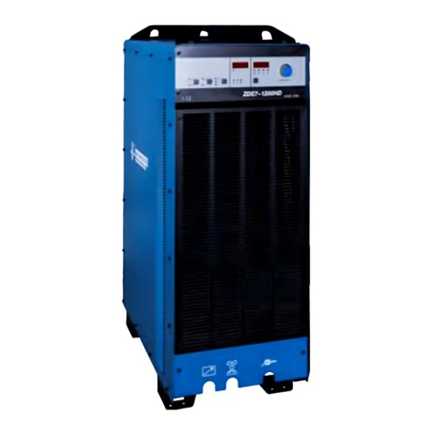
Hwayuan Electric ZDE7-1200HD User manual

ZDE7-1200HD
INVERTER AC/DC SUBMERGED ARC WELDING MACHINE
MANUAL
INSTRUCTION
(PLEASE READ IT CAREFULLY BEFORE OPERATION)

S a f e ty De p e n d s o n Y o u
The arc welding and cutting equipments are designed and built with ample safety consideration. However, proper installing
and operating the machine can increase your safety.
DO NOT INSTALL, OPERATE OR REPAIR THIS EQUIPMENT CASUALLY WITHOUT READING THIS MANUAL THROUGHOUT.
S p e ci a l A t t e n t i o n ( V er y I m p o r t a n t ) :
BE SURE TO AVOID THE WELDING MACHINE FALLING DOWN WHEN IT IS PLACED ON THE GRADIENT GROUND.
IT’S FORBIDDEN UNFREEZING THE PIPELINE BY THE WELDING MACHINE.
THE SHIELD RANK OF THIS SERIAS OF WELDING MACHINES IS IP21S, SO WORKING IN RAIN IS NOT SUTABLE.
This machine EMC is A.
Purchase Date:___________________
Serial Number:____________________
Machine Type:____________________
Purchase Place:____________________

CONTENT
1 Safety warnings .............................................................................................................. 3
2 Product summary ........................................................................................................... 1
3 Technical parameters ...................................................................................................... 3
4 Panel function ................................................................................................................ 5
5 Insert function ................................................................................................................ 7
6 Machine Installation ..................................................................................................... 10
7 Operation ..................................................................................................................... 17
8 Working principle ..........................................................................................................21
9 Maintenance, repair and discard ...................................................................................21
10 Trouble shooting ........................................................................................................22
11 Packing list ................................................................................................................ 25
12 Electric Diagram .........................................................................................................26

1 Safety warnings
Cautions
Arc and arc rays can hurt.
All performing welding workers ought to have health qualification from the authority organization to prevent you and
others from arc radiation and burn. It should be prevented for children to enter into dangerous area as well.
Be careful reading the following important items and the welder safety byelaw from the authority organization. Be sure
that qualified professionals perform all installation, maintenances and repair procedures.
1 Electric shock: The welding circuits are not insulated when welding. If you touch the two output
electrodes of the machine with your bare skin at the same time, it will lead to electric shock,
sometimes even fatal dangers. Users need to follow the items below to avoid electric shocks:
If possible, lay some insulating materials, which are dry and large enough, in your working field. Otherwise, use the
automatic or semiautomatic welding machine, DC welding machine as possible as you can.
Components in the automatic and semiautomatic welding machine such as the welding wire reel, feed wheel,
contact tip and welding head are all electriferous.
Always be sure the machine has been connected perfectly to the work piece with the work cables and should be as
close as possible to the working area.
The work piece should be grounded perfectly.
Make sure that the insulating material of the electrode holder, the grounding clamp, the welding cable and the
welding head are not affected by damp, mildewed or spoilt, and be replaced momentarily.
Never dip the electrode in water for cooling.
Never touch electriferous parts of two welding machines at the same time, because this voltage is supposed to be
two times of welding voltage while the grounding mode is not clear.
While working high above the ground or other places having the risk of falling, please be sure to wear safety belt
to avoid losing balance caused by electric shock.
2 Arc: Use an arc welding mask to protect your eyes and skin from sparks and the rays of the arc, pay
special attention to the filter glass, which must be conformable to the national standard.
Use clothing made from durable flame-resistant material or sailcloth to protect your skin from
hurting by the arc rays.
Remind other nearby personnel before working lest arc rays hurt them by accident.
3 Fumes and Gases: Welding may produce fumes and gases hazardous to health. Avoid breathing
these fumes and gases. While working in limited room, use enough ventilation and/or exhaust to keep
fumes and gases away from the breathing zone, or use the respirator. Do not weld at the same time
when using of degreasing, cleaning or spraying operations. The heat and rays of the arc can react with these gases to
form phosgene, a highly toxic gas,
Some protective gases used in welding might displace the oxygen in the air, and can lead to hurt or even death.
Read and understand the manufacturer’s instructions for this equipment, and validate the health certification of
consumptive materials, make sure they are asepsis and innocuity.
4 Spatter: Spatter can cause fire or explosion.
Remove fire hazards from the welding area. Remember that spatter from welding can easily go
through small cracks and touch fire hazards. Keep the safety of all kinds of lines going though

welding area, including hydraulic lines in the wild.
Where compressed gases are to be used in the field, special precautions should be used to prevent explosion.
When not welding, make certain that no electriferous part is touching the work piece or the work stage. Accidental
contact can create a fire hazard.
Do not weld containers or lines, which are not proved to be innocuous.
It is very dangerous to heat, cut or weld tanks or containers at entry holes. Does not start work until the proper
steps have been taken to insure that there is no flammable or toxic gas.
Spatter might cause burn. Wear leather gloves, heavy shirt, cuffless trousers, high shoes and a cap over your hair
to prevent from burning by spatter. Wear the ear shield when performing sideways or face up welding. Always
wear safety glasses with side shields when being in a welding area.
The welding cables should be as close to the welding area as possible, and the short, the better. Avoid welding
cables going through the building framework, lifting chains, AC or DC cables of other welding machines and
appliances. The welding current is strong enough to damage them while having short circuit with them.
5 Cylinder: Damage of it might cause explosion.
Make sure that the gas in the storage cylinder is qualified for welding, and the decompression
flow-meter, the adapter and the pipe are all in good condition.
Make sure that the installation of cylinder is by the wall and bundled tightly by a chain.
Be sure to put the cylinder in the working space with no crash or shake, and far from welding area.
It is forbidden to touch cylinder with the welding clamp or the work cables.
Avoid facing the cylinder while installing the decompression flow-meter or the gasometer.
When not working, please tighten the valve.
6 Power: (For electrically powered welding and cutting equipment) Turn off input power before
installation, maintenances and repair, so that avoid accident.
The welding equipment is Ι class safeguard equipment; please install the equipment in
accordance with the manufacturer’s recommendations by specific persons.
Ground the equipment perfectly in accordance with the manufacturer’s recommendations.
7 Power:(For engine driven welding and cutting equipment)
Work in ventilated place or outdoors.
Do not add fuel near to fire or during engine starting or welding. When not working, add fuel after
engine is cooling down; otherwise, the evaporation of hot fuel would result in dangers. Do not
splash fuel out of the fuel tank, and do not start the engine until complete evaporation of the
outside fuel.
Make sure that all the safeguard equipments, machine cover and devices are all in a good
condition. Be sure that arms, clothes and all the tools do not touch all the moving and rotating
components including V belt, gear and fan etc.
Sometimes having to dismantle some parts of the device during maintenance, but must keep safety awareness
strongly every time.
Do not put your hand close to fans and do not move the brake handle while operating.
Please remove the connection between the engine and the welding equipment to avoid sudden starting bn
When engine is hot, it is forbidden to open the airtight cover of the radiator water tank to avoid hurt by the hot
vapor.
8 Electromagnetic: Welding current going though any area can generate electromagnetic, as well as the
welding equipment itself.
Electromagnetic would affect cardiac pacemaker, the cardiac pacemaker users should consult

one’s doctor first.
The effect of electromagnetic to one’s health is not confirmed, so it might have some negative effect to one’s
health.
Welders may use following method to reduce the hazardous of electromagnetic:
a. Bundle the cable connected to the work piece and the welding cable together.
b. Do not enwind partially or entirely your body with the cable.
c. Do not place yourself between the welding cable and the ground (work piece) cable, if the welding cable is by your
left side, then the ground cable should be by your left side too.
d. The Welding cable and the ground cable are as short as possible.
e. Do not work near to the welding power source.
9 Lift Equipment: carton or wooden boxes package the welding machines supplied by our company.
There is no lifting equipment in its wrapper. Users can move it to the prospective area by a fork-lift
truck, and then open the box.
If having rings, the machine can be transited using rings. While D&H SÉCHERON Welding Machine
Manufacture reminds users, there is possible risk to damage the welding machine. It is better to
push the welding machine moving in use of its rollers unless special situations.
Be sure that the appurtenances are all removed off when lifting.
When lifting, make sure that there is no person below the welding machine, and remind people
passing by at any moment.
Do not move the hoist too fast.
10 Noise: The Welding Machine Manufacturer reminds users: Noise beyond the limit (over 80 db) can
cause injury to vision, heart and audition depending on oneself. Please consult local medical
institution. Use the equipment with doctor’s permission would help to keeping healthy.
Machine used for pipe unfreezing purpose is prohibited.

1
2 Product summary
2.1 Model instruction
2.2 Main features
1. Adopting digital control technology, easy to operate with beautiful outlook.
2. With arc voltage inspection and sensor react technology, welding cable can lengthen to 70m
3. 100% duty cycle, suitable for heavy industry
4. Software technology, with small volume, light weight and low consumption
5. With AC square wave control technology, adjustable AC frequency, DC deviation and wave balance parameter to improve
the arc voltage stability, control the welding seam depth and deposition speed to get good performance
6. With AC/DC revert connection and DCEN connection exchange function, can get exchange without change the cable
connection
7. Power source can parallel to work to enlarge the output current, which suitable for huge current welding situation and
increase the efficiency
2.3 Application
This AC/DC square wave arc welding rectifier is a power source with multi-functions for submerged arc welding.
Except for good functions with AC/ DC single wire welding and surfacing with band-electrode, it can do twin or
multi wire welding with DC arc welding power source.
Power source can parallel to work to enlarge the output current, which suitable for huge current welding situation.
Widely used for steel structure, bridge, automotive, oven and water electricity filed.

2
2.4 Working circumstance
The machine protection grade is IP21S, can’t work or stock under the rain
Working in living quarters is not recommended
Ambient temperature range:When welding:-10~+40℃;transport and store -25~+55℃
Relative humidity:40℃≤50%;20℃≤90%
The dust, corrosive and acid air or material should be within normal range, except the air come from the welding
process.
The tilting should be no more than 10°,if machine work on the tilting place, anti-tilting measurements should be taken.
Distance from machine to machine, from machine to wall should be more than 50cm.
Working situation should fit standard of GB/T8118-2010。
2.5 Symbol instruction
Read instruction manual
Danger
overheat
Input 3-380V
Input abnormal
Power indicator
Input control
Output control
Remote control
Panel control
CC
CV
AC
DC
AC frequency
DCEP
Wave balance
DCEN
DC deposition
Parameter value adjust
Welding head
SAW
Work piece
Work piece arc voltage input
Control transformer fuse
Ground connect

3
3 Technical parameters
3.1 Technical parameter
Item
Unit
Model
ZDE7-1200HD
Input Power
V/Hz
3~380/415 ±10% 50
Rated Input Capacity
KVA
63.8
Rated Input Current
A
104
Rated Output Current
A
1200
Rated Output Voltage
V
44
Rated AC Output Current/Voltage Range
-
100A/20V~1200A/44V
Rated Open Circuit Voltage
V
92
Rated Duty Cycle
-
100%(40℃)
Efficiency
-
78%
Power Factor
-
0.91
Wave Shape Balance
%
25~75
DC Bias
%
25~75
Cooling Mode
-
Air Cooling
Insulation Grade
-
F
Ingress Protection
-
IP21S
Dimension (L*W*H)
mm
930x470x1250
Net Weight
kg
180
3.2 Characteristics
(1)Slowly CC mode
(2)CV model

4
(3)Sharply CC mode
3.3 Rated duty cycle
Rated duty cycle X=100% means take 10min as a circle, machine can work 10min, that means machine can 24 hours work
without stop. The machine working is under temperature -10℃~+40℃,if ambient temperature over 40℃or too much dust
inside the machine will cause the duty cycle reduce, maybe the machine will be burnt.
3.4 Overheat protection
This machine adopt temperature relay for heat protection, if machine work over the rated duty cycle or ambient
temperature over 40℃cause machine over heat, the temperature relay will stop the machine to avoid burnt.
Machine can continue to work when the inside temperature turn to normal and the overheat indicator off.

5
4 Panel function
4.1 Front top panel instruction
1. Ammeter:Indicate the actual welding current;;
2. Voltmeter:Indicate the actual welding voltage;
3. PARAMETER ADJ.):adjust the welding current under panel control, adjust AC frequency, wave balance and DC
deposition parameter under remote control
4. Power supply indicator:to indicate if the power is energized;
5. Over-load indicator:when machine is under over-load, the indicator lamp is on;
6. Voltage abnormal indicator:when the voltage is abnormal, the indicator lamp is on;
7. Parameter selection: select AC frequency, wave balance and DC deposition under AC mode;
8. Current indicator: it will be on when ammeter show current value.
9. AC frequency( ) indicator: it will be on when ammeter show AC frequency(Hz), can adjust the AC frequency
parameter by turn the knob.
10. Wave balance( ) indicator: it will be on when ammeter show the wave balance(%), can adjust the wave
balance parameter by turn the knob.
11. DC deposition ( ) indicator: it will be on when ammeter show the DC deposition (%), can adjust the DC
deposition parameter by turn the knob.
AC frequency, wave balance and DC deposition indicator select by the parameter adjust knob, 3s after adjustment finish,
the indicator will automatically turn to current indicator on.
12. Polarity select knob: AC/DCEP/DCEN exchange knob
13. AC( )indicator: it will be on when under AC function
14. DCEP(DC+)indicator: it will be on when under DCEP function(welding head terminal is +,work piece terminal is -)
15. DCEN(DC-)indicator: it will be on when under DCEN function(welding head terminal is -,work piece terminal is +)
16. Characteristic select knob: CC and CV mode exchange knob
17. CC mode( )indicator: it will be on when under CC mode(it is slow CC under remote control, sharp CC under
panel control)
18. CV mode( )indicator: it will be on when under CV mode(no such function under panel control)
19. Control selection knob: remote control and panel control exchange knob.

6
20. Panel control( )indicator: machine under panel control when indicator on
21. Remote control( )indicator: machine under remote control when indicator on
4.2 Front bottom panel instruction
1. Remote control plug: power source remote control communication plug, the pin function of the plug as following
table:
2.Welding head( )output terminal: connect with cable from welding head side
3.Work piece( )output terminal: connect with cable from work piece side
4.Arc voltage inspection signal: work piece side arc voltage inspection signal input( )terminal,connect with arc
voltage inspection cable from work piece side
Pin
Name
Function
Note
1
Remote control A
Start signal
Remote control and panel control affected by this signal
2
H
Power given signal
Together with pin 4 output 15V signal, inside power have
150Ω resistor
3
D
Power given signal
Input , resistor>10MΩ,0~15V
4
L
Power given signal
Short connect with pin 12 (GND)inside the machine
5
Remote control B
Start signal
Input together with pin 1(A) , back circuit current <
50mA
6
Arc volt.(work piece)
Arc volt. inspection signal
Output
7
~110VA
AC 110V
Output, isolate from the three phase input power,
frequency(50Hz/60Hz), power 250W
8
~110VB
AC 110V
Output
9
Arc volt.(welding head)
Arc volt. inspection signal
Input
10
PE
Connect shell
Not connect
11
I
Current feedback signal
Output ,welding current/current feedback signal =
(1000A/4V)
12
GND
Ground connect
Reference terminal for pin 3 and pin 11

7
4.3 Back panel instruction
(1)Power switch: over current protection switch, when machine abnormal, this switch will power off to protect the
machine. Please separately connect power switch when install the machine
(2)Communication plug X1: power source parallel control connecter or synchronize control communication plug, input
plug ( ) . Pin 1 is for whole communication signal A, pin 2 is for whole communication signal B, other 5 pin is for
reservation.
(3)Communication plug X2: power source parallel control connecter or synchronize control communication plug, input
plug ( ) . Pin 1 is for whole communication signal A, pin 2 is for whole communication signal B, other 5 pin is for
reservation.
(4)Fuse FU1(5A): used for control transformer over current protection(control circuit, fan, remote control output)
( ).Make sure the power source is no electricity when turn on the fuse.
(5)Power cable connector: three phase power input( );
(6)Ground connect( )screw(M8): must be stable and fit the state standard
(7)Cable fix block: to fix the three phase input cable
5 Insert function
No.
Item
Factory set
Instruction

8
No.
Item
Factory set
Instruction
1.
Penetration set on DCEP
1(on)
1 gear
Step 1: press “parameter selection” for 5s, come into insert function set
mode, voltmeter show “00.”
Step 2: adjust “parameter adjust” make ammeter show “2”, press
“characteristic select”, come into DCEP penetration setting
Step 3: voltmeter show “0”, turn “parameter adjust”, press “pole selection”
when ammeter show “0”, to turn off the penetration adjust t and exit from
the insert function set. Press “pole selection” when ammeter show “1”, to
start the penetration set
Step 4: voltmeter show “1”, turn “parameter adjust”, penetration have 4 gear
select(1st gear the penetration is lightest, the 4th gear penetration is
deepest), press “pole select” to storage then exit.
2.
Up/down slope adjust for AC current exchange
0(off)
Step 1: press “parameter selection” for 5s, come into insert function set
mode, voltmeter show “00.”
Step 2: adjust “parameter adjust” make ammeter show “3”, press
“characteristic select”, come into AC current up/down slope adjust setting
Step 3: voltmeter show “0”, turn “parameter adjust”, press “pole selection”
when ammeter show “0”, to turn off the slope adjust and exit from the insert
function set. Press “pole selection” when ammeter show “1”, to start the
slope control
Step 4: voltmeter show “1”, turn “parameter adjust”, adjust AC up/down
slope (1~100(A/100μs))press “pole select” storage ,the value is 10
Step 5: voltmeter show “2”, up slope and down slope value set same, press
“pole select” to storage, then exit.
3.
System reboot
Step 1: press “parameter selection” for 5s, come into insert function set
mode, voltmeter show “00.”
Step 2: adjust “parameter adjust” make ammeter show “7”, press
“characteristic select”, come into factory set, storage and exit.
4.
Parallel function
0(off)
Step 1: press “parameter
selection” for 5s, come into insert
function set mode, voltmeter show
“00.”
Step 2: adjust “parameter adjust”
make ammeter show “5”, press
“characteristic select”, come into
parallel and multi arc control
Step 4: voltmeter show “0”, set
the master and deputy source,
turn “parameter adjust”, press
“pole selection” when ammeter
show “0”, to set the deputy
power source, Press “pole
selection” when ammeter show
“1”, to set the master power
source

9
No.
Item
Factory set
Instruction
setting
Step 3: voltmeter show “0”, turn
“parameter adjust”, press “pole
selection” when ammeter show
“0”, to off the parallel and multi arc
mode, then exit from insert
function. Press “pole selection”
when ammeter show “1”, to open
the parallel function, when
ammeter show “2” to open the
multi arc function
Multi-function
0(off)
Step 5: voltmeter show “2”, to
set the arc order, turn
“parameter adjust”, press “pole
selection” when ammeter show
“1”, to set the first arc, Press
“pole selection” when ammeter
show “2-6”, to set the 2nd to 6th
arc.
5.
Lack voltage and phase inspection
280
Step 1: press “parameter selection” for 5s, come into insert function set
mode, voltmeter show “00.”
Step 2: adjust “parameter adjust” make ammeter show “7”, press
“characteristic select”, come into “input abnormal inspection”
Step 3: voltmeter show “0”, turn “parameter adjust”, ammeter show
230~330(this value bigger, the voltage inspection sensitive higher),
press ”pole selection” to storage the parameter, then exit.
6.
Remote control start set
0
(on remote control when start)
Step 1: press “parameter selection” for 5s, come into insert function set
mode, voltmeter show “00.”
Step 2: adjust “parameter adjust” make ammeter show “7”, press
“characteristic select”, come into panel control start setting
Step 3: voltmeter show “0”, turn “parameter adjust”, press “pole selection”
when ammeter show “0”, set the power source start on remote control
terminal. Press “pole selection” when ammeter show “1”, set the power
source start automatically, storage and exit.
*Insert function: can set on the front up panel as the above table 4 shows.
*Power source protection function: 6s after power on, the machine can have output.

10
*Intelligent fan function: fan work 2s after machine power source. It continue work on remote control mode. It start to work
when machine power on under remote control mode, and stop work 8min after machine stop work. Each time the fan
start/stop time need no less than 5s. it continue work under overheat situation.
6 Machine Installation
6.1 Hoisting
As following drawing show,(1)、(2)、(3)(4)hoisting hole,can choose(1)and(4)or(2)and(3)or(1)、
(2)、(3)(4)together
6.2 6Foot install dimension
As following drawing show:

11
6.3 6Machine connection
6.3.1、Input power cable connection
This machine requires 3 phase 380v/50Hz power input, so the related power cable and distribution box is needed, as well as
the circuit breaker and ground lead. Reliably connect the protective ground and the yellow-green wire which on the back of
the machine. The wire CSA should no less than the following table:
Model
CSA for input copper
wire (mm2)
Breaker capacity
(A)
Fuse protector
(A)
CSA for ground lead
cable(mm2)
ZDE7-1200HD
≥25
≥16
150
≥150
6.3.2、Output terminal cable connection
(1)Take away the protection pad of the output terminal, connect the welding head and work piece stably with the
power source output terminal, make sure the protection pad ≥10mm away from the cables after the pad installed. Welding
cable shall be no less than 140mm2.
(2)When power source integrated, the control cable one side connect power source output terminal stably, the other
side connect controller, make sure the 12 pin control cable no less than 0.75mm2
(3)Connect one side of the arc voltage inspection cable stably with the power source bottom panel arc voltage
inspection signal terminal, the other side connect with work piece, the cable should be no less than 1.0mm2
6.3.3、Notes for output terminal cable connection
(1)Welding cable square meter small or connect not stable will cause welding performance. Make sure the cable
square meter is big enough and connection is stable. The overheat of the cable shall be caused by small cable or connect

12
unstable.
(2)Make the cable roll up, like the following drawing 12(a)show is prohibited. If roll up is unavoidable, it better use
the way like 12(b)show, make the welding head cable and work cable nearby to reduce circuit inductance.
(a)
(b)
Drawing 12
(3)When work piece too long, it better use slipper mode for ground connect to reduce the cable length, welding cable
length shall be no more than 70m.
(4)Too much inductance for the welding circuit will cause SC welding current and voltage unstable, cause the power
source stability and burn the parts inside.
(5)Arc voltage inspection cable connect with welding cable is prohibited to avoid inductance.
(6)Arc voltage inspection cable shall be as short as possible to reduce the inductance
(7)Taking the position opposite from the work piece during the welding can get better welding performance

13
(8)When the power used for multi arc and parallel function, after ensure the min. distance for each power source, the
communication cable shall be the shorter the better , communication cable shall be less than 1200m
6.3.4、Single wire connection
(1)Work with single wire tractor
Drawing 13
Turn off the three phase input breaker, connect two power source as drawing 13 shows, connect three phase power
source, earth cable, welding head side cable, work piece side cable, 12 pin control cable and arc voltage inspection cable
accordingly.

14
(2)Work with gantry machine
Drawing 14
Turn off the three phase input breaker, connect two power source as drawing 13 shows, connect three phase power
source, earth cable, welding head side cable, work piece side cable, 12 pin control cable and arc voltage inspection cable
accordingly.
6.3.5、Tandem connection
Drawing 15
Table of contents
Other Hwayuan Electric Welding System manuals

Hwayuan Electric
Hwayuan Electric NB-250/315LT User manual

Hwayuan Electric
Hwayuan Electric LGK-100GBT User manual

Hwayuan Electric
Hwayuan Electric ZX7-315IGBT User manual

Hwayuan Electric
Hwayuan Electric LGK-40/63IGBT User manual

Hwayuan Electric
Hwayuan Electric ZX7-200 User manual

Hwayuan Electric
Hwayuan Electric ZDE7-1200 User manual