OPERATING PROCEDURES
MP35.372C
12JUL06
CAUTION:
IMPORTANT:
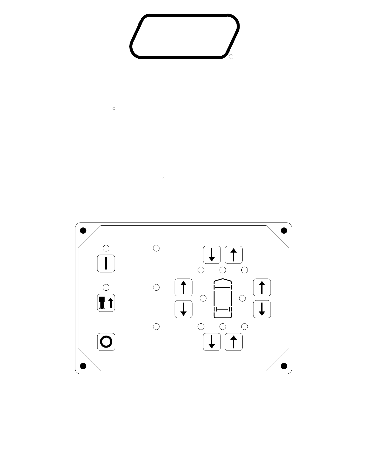
JACK RETRACTION
THE OPERATOR MUST BE SURE THAT
THERE ARE NO OBJECTS UNDER THE VEHICLE AND
THAT ALL PEOPLE ARE CLEAR OF THE VEHICLE.
DO NOT interrupt power to the leveling
system while the "STORE" indicator light is blinking.
DO NOT push the "OFF" button. The system must be allowed
4. If jacks cannot be retracted by the above procedure see
MANUAL JACK RETRACTION Section.
to completely finish the store mode. If the engine was started
2. Press the "STORE" button. The store indicator light will
flash. As each jack retracts, its red WARNING light will go
1. Turn the ignition switch to "ON", "ACC", or start the engine.
Press the "I" button one time. The "I" indicator light will glow
steady.
out. The vehicle can be moved as soon as the red WARNING
lights are out and the green "TRAVEL" light is on, providing
the jacks are in the STORE/TRAVEL position.
before putting the system in the store mode, the vehicle may
be moved when the jacks are in the STORE/TRAVEL position.
This will not interrupt the store procedure.
3. The system will automatically shut down six minutes after
the four individual red "WARNING" lights are out. If any one
red "WARNING" light does not go out, the system will
continue to store for thirty (30) minutes, then shut down
regardless of the "WARNING" lights condition.
THE STORE/TRAVEL POSITION BEFORE TRAVELING.
RESPONSIBILITY TO CHECK THAT ALL JACKS ARE IN
WARNING LIGHTS. IT IS THE OPERATOR’S
CAUTION: DO NOT RELY SOLELY UPON THE
NOTE: If the ROOM CONTROL SWITCH is pushed while
the Leveling System is in the "STORE" mode, the STORE
procedure is interrupted until the ROOM CONTROL SWITCH
is released. If the four red WARNING lights are all out, the
STORE light will continue to blink for six minutes, then the
system will shut off.
MANUAL HYDRAULIC OPERATION
"ACCESSORY" or "ON" position.
the vehicle, and set the parking brake. Turn the ignition to the
SENSING light is on, that side or end of the vehicle is low.
buttons on the right half of the panel. If a yellow LEVEL
3. The vehicle may be leveled using the manual EXTEND
2. Press the "I" button. The indicator light will glow steady.
1. Place transmission in the recommended position for parking
Do not continue to push an EXTEND button
leveling panel and turn the ignition switch to the "OFF"
4. When leveling is completed, push the "OFF" button on the
for more than ten (10) seconds after that pair of jacks are
leveling can be extended to the ground. This provides
Any jack not used for
additional stability against wind and activity in the vehicle.
fully extended.
IMPORTANT:
Jacks will extend (or retract) in pairs to raise (or lower) a side
or end of the vehicle.
Level the vehicle side to side, if necessary, before
leveling the vehicle front to rear.
position.
NOTE: As the jacks extend 1/4" to 1/2" the
red warning light for the jack will come on.
STORE/TRAVEL POSITION
JACK POSITIONS
EXTENDED POSITION