HWH 625 Series User manual

OPERATOR’S MANUAL
ML40394/MP04.2802
08MAR07
Touch Panel Leveling Control
BI-AXIS Hydraulic Leveling
FEATURING:
HWH CORPORATION
(On I-80, Exit 267 South)
2096 Moscow Road | Moscow, Iowa 52760
Ph: 800/321-3494 (or) 563/724-3396 | Fax: 563/724-3408
www.hwh.com
625 SERIES LEVELING SYSTEM
HWH COMPUTER-CONTROLLED
R
Straight-Acting Jacks
AP40393
R
With Optional Air Dump
UNDERSTAND OPERATOR’S MANUAL BEFORE USING. BLOCK FRAME AND TIRES
SECURELY BEFORE REMOVING TIRES OR CRAWLING UNDER VEHICLE.
HWH COMPUTERIZED LEVELING
EXTEND
RETRACT
AUTO
CAUTION!
EMERGENCY
STOP
MANUALAUTO
STORE
LEVEL
DUMP
TRAVEL
MODE
PARK/
NOT IN
BRAKE
R
SLOPE
EXCESS
EXTEND
RETRACT
MANUAL
W
CORPORATION
HH
R

CAUTION !
READ THE ENTIRE OPERATOR MANUAL BEFORE OPERATING.
BLOCK FRAME AND TIRES SECURELY BEFORE CRAWLING UNDER VEHICLE. DO NOT USE LEVELING JACKS OR
AIR SUSPENSION TO SUPPORT VEHICLE WHILE UNDER VEHICLE OR CHANGING TIRES. VEHICLE MAY DROP
AND/OR MOVE FORWARD OR BACKWARD WITHOUT WARNING CAUSING INJURY OR DEATH.
WEAR SAFETY GLASSES WHEN INSPECTING OR SERVICING THE SYSTEM TO PROTECT EYES FROM DIRT, METAL
CHIPS, OIL LEAKS, ETC. FOLLOW ALL OTHER APPLICABLE SHOP SAFETY PRACTICES.
OPERATOR’S MANUAL
KEEP ALL PEOPLE CLEAR OF VEHICLE WHILE DUMPING AIR FROM THE VEHICLE’S SUSPENSION.
DO NOT MOVE THE VEHICLE IF THE VEHICLE IS NOT AT THE PROPER RIDE HEIGHT. CONTACT MANUFACTURER
IMPORTANT: IF COACH IS EQUIPPED WITH A ROOM EXTENSION, READ ROOM EXTENSION SECTION BEFORE
OPERATING LEVELING SYSTEM.
HOW TO OBTAIN WARRANTY SERVICE
THIS IS NOT TO BE INTERPRETED AS A STATEMENT OF WARRANTY
HWH CORPORATION strives to maintain the highest level of
customer satisfaction. Therefore, if you discover a defect or
problem, please do the following:
(563) 724-3396 OR (800) 321-3494. Give your name and
coach was purchased, or the date of system installation,
Notify the dealership where you purchased the
vehicle or had the leveling system installed. Dealership
management people are in the best position to resolve
the problem quickly. If the dealer has difficulty solving
the problem, he should immediately contact the Customer
Service Department, at HWH CORPORATION.
If your dealer cannot or will not solve the problem,
notify the Customer Service Department:
HWH CORPORATION 2096 Moscow Rd. Moscow IA. 52760
address, coach manufacturer and model year, date the
SECOND:
FIRST:
authorization of an independent service facility, to be
defective part, either by appointment at the factory or by the
CORPORATION will authorize repair or replacement of the
determine whether or not your claim is valid. If it is, HWH
HWH CORPORATION personnel will contact you to
during business hours (8:00 a.m. till 5:00 p.m. c.s.t.).
description of the problem, and where you can be reached
determined by HWH CORPORATION. All warranty repairs
must be performed by an independent service facility
authorized by HWH CORPORATION, or at the
HWH CORPORATION factory, unless prior written approval
has been obtained from proper HWH CORPORATION
personnel.
23FEB07
MP14.0002
TECHNICAL SERVICE FOR MOVING THE VEHICLE WHEN NOT AT THE PROPER RIDE HEIGHT.
KEEP ALL PEOPLE CLEAR OF VEHICLE WHILE OPERATING LEVELING SYSTEM OR ROOM EXTENSIONS.

MP24.2852
08MAR07
"EMERGENCY STOP" BUTTON:
any leveling system operation.
"AUTO LEVEL" BUTTON:
"AUTO STORE" BUTTON:
four jacks at the same time. WARNING LIGHTS:
"EXCESS SLOPE" LIGHT:
the leveling system cannot level the vehicle.
"NOT IN PARK/BRAKE" LIGHT:
when the hand/auto brake is not set and the "AUTO LEVEL"
"TRAVEL MODE" LIGHT:
when the ignition is on, when the jacks are retracted and
there are no red WARNING lights on.
MASTER "JACKS DOWN" WARNING LIGHT:
light mounted in the dash separate from the touch panel.
and the ignition is "ON".
BUZZER:
CONTROL FUNCTIONS
INDICATOR LIGHTS (CONTINUED)
CONTROL BUTTONS
Push this button to stop
Push this button to retract all
This indicator will light when
This indicator will light
This indicator light will be on
This is a
This is a jacks down warning.
EXTEND BUTTONS (UP ARROWS):
RETRACT BUTTONS (DOWN ARROWS):
LEVELING LIGHTS:
These buttons will
extend their respective jack pairs to lift the vehicle.
These buttons
will retract their respective jack pairs to lower the vehicle.
The four yellow indicating lights are
level sensing indicators. When a yellow light is on, it
indicates that its side, end, or corner of the vehicle is low.
No more than two lights should be on at the same time.Push this button any time to
The four red lights surrounding the
yellow level indicators are jacks down WARNING lights.
They are functional only when the ignition is in the "ON"
extended 1/4 to 1/2 inch.
start the automatic leveling function.
It will sound if the master "JACKS DOWN"
CONTROL IDENTIFICATION
625 SERIES LEVELING SYSTEM
COMPUTER-CONTROL
or "ACC" position, the system is on, and the jacks are
It will be on when any one or more jacks are extended
button is being pushed.
RETRACT
EXTEND
HWH COMPUTERIZED LEVELING
SECURELY BEFORE REMOVING TIRES OR CRAWLING UNDER VEHICLE.
UNDERSTAND OPERATOR’S MANUAL BEFORE USING. BLOCK FRAME AND TIRES
"EXCESS SLOPE"
Indicator light
"AUTO LEVEL"
AUTO LEVEL/STORE
CANCEL Button
"NOT IN PARK"
Indicator light
Indicator light
"TRAVEL MODE"
Indicator light
Indicator light
AUTO LEVEL
"AUTO STORE"
Button
STORE
Button
RAISE LEFT SIDE
Manual button
LOWER LEFT SIDE
Manual button
EMERGENCY
STORE
AUTO
STOP
AUTO
LEVEL
TRAVEL
BRAKE
MODE
CAUTION!
EXCESS
SLOPE
NOT IN
PARK/
R
LOWER FRONT
Manual button
RAISE FRONT
Manual button
JACK DOWN
Indicator light
RAISE RIGHT SIDE
Manual button
LOWER RIGHT SIDE
Manual button
LEVEL SENSING
Indicator light
(4) yellow
RAISE REAR
Manual button
LOWER REAR
Manual button
MANUAL
RETRACT
EXTEND (4) red
INDICATOR LIGHTS
AUTO LEVEL INDICATOR LIGHT: This light will flash
during the automatic leveling function.
STORE INDICATOR LIGHT: This light will flash during
the automatic store function.
When all four yellow LEVEL lights are out, the vehicle is
level. SEE OPERATOR’S PROCEDURES - AUTOMATIC
MANUAL
DUMP
"MANUAL DUMP"
Button
warning light is on.
"MANUAL DUMP" BUTTON: This is a manual button for
dumping air from the vehicle suspension.
HYDRAULIC LEVELING FOR DETAILED EXPLANATION.

OPERATING PROCEDURES
MP34.0205
08MAR07
GENERAL INSTRUCTIONS
PREPARATION FOR TRAVEL
If parking on soft ground or asphalt paving, a wood block or
pad should be placed under each jack.
Any time a hydraulic leveling process is interrupted, retract
the jacks according to the JACK RETRACTION Section and
then restart the leveling process.
If the hand / auto brake is not set when the "AUTO LEVEL"
button is pressed, the "NOT IN PARK/BRAKE" light will
come on. When the "AUTO LEVEL" button is released the
If the jacks are retracted but a red "WARNING" light is lit
the system needs to be serviced.
If the jacks cannot be retracted according to the JACK
RETRACTION Section, retract the jacks according to the
MANUAL JACK RETRACTION Section. The system
should then be checked.
The leveling system should be cycled once a month or
whenever the vehicle is used, to keep the system in
operating condition.
Maintain adequate clearance in all directions for vehicle, room
extensions, awnings, doors, steps, etc. Vehicle may move in
any direction due to jacks extending or retracting, settling of
the jacks or the vehicle, equipment malfunction, etc..
Any room extension or generator slide should be fully
DO NOT MOVE THE VEHICLE IF ONE
OR MORE JACKS ARE EXTENDED TO THE GROUND.
CAUTION:
"NOT IN PARK/BRAKE" light will go out. The Automatic
retracted before traveling.
Leveling function will not start.
Press the "EMERGENCY STOP" button or turn the ignition
switch "OFF" at any time to stop the operation of the system.
fail to retract completely, extend the jacks back down
to the ground then retract the jacks again.
NOTE: If the vehicle is parked or stored with the jacks
extended for an extended period of time and the jacks
IMPORTANT: Before traveling, the red jack warning
lights must be off the "TRAVEL MODE" light must be on
and he vehicle should be at the proper height for travel.
If lights are not correct for travel, retract jack as
THE LEVELING JACKS ARE STILL IN CONTACT WITH
THE GROUND OR IN THE EXTEND POSITION. THIS
VEHICLE IS EQUIPPED WITH STRAIGHT-ACTING JACKS.
MOVING THE VEHICLE WITH THE LEVELING JACKS
EXTENDED CAN CAUSE SEVERE DAMAGE TO THE
CAUTION:DO NOT MOVE THE VEHICLE WHILE
TRAVELING. CONTACT MANUFACTURER TECHNICAL
SERVICE BEFORE MOVING A VEHICLE THAT IS NOT
AT PROPER TRAVEL HEIGHT.
VEHICLE IS AT THE PROPER RIDE HEIGHT FOR
INTO THE STORE/TRAVEL POSITION AND THE
JACKS AND OR THE VEHICLE AND CREATE A DRIVING
HAZARD. DO NOT RELY SOLELY UPON WARNING
LIGHTS. IT IS THE OPERATOR’S RESPONSIBILITY
TO CHECK THAT ALL JACKS ARE FULLY RETRACTED
described in the JACK RETRACTION Section.
ROOM EXTENSION PROCEDURES
It is recommended to retract room extensions before
the Leveling Procedure before operating room extensions.
MUST be blocked securely. It is recommended to complete
If the vehicle is equipped with kick-down jacks, the wheels
extension read this section carefully.
IMPORTANT: If the vehicle is equipped with a room
retracting jacks.
when the vehicle is supported by the leveling system.
Refer to the vehicle owners manual for proper operation of
IMPORTANT: Do not use a room extension support
room extensions.
NOTE: This manual is intended for vehicles with a spring
or air suspension. If the vehicle has an air suspension
with a manual pilot air dump, refer to the vehicle
manufacturer for operating instructions.

MP34.2707
08MAR07
AUTOMATIC HYDRAULIC LEVELING
1. Place transmission in the recommended position for
parking the vehicle and set parking brake. Turn the coach
engine off. Turn the ignition to the "ACCESSORY" position.
2. At this time, the operator may want to check the jacks
and place a pad under each jack if the ground will not
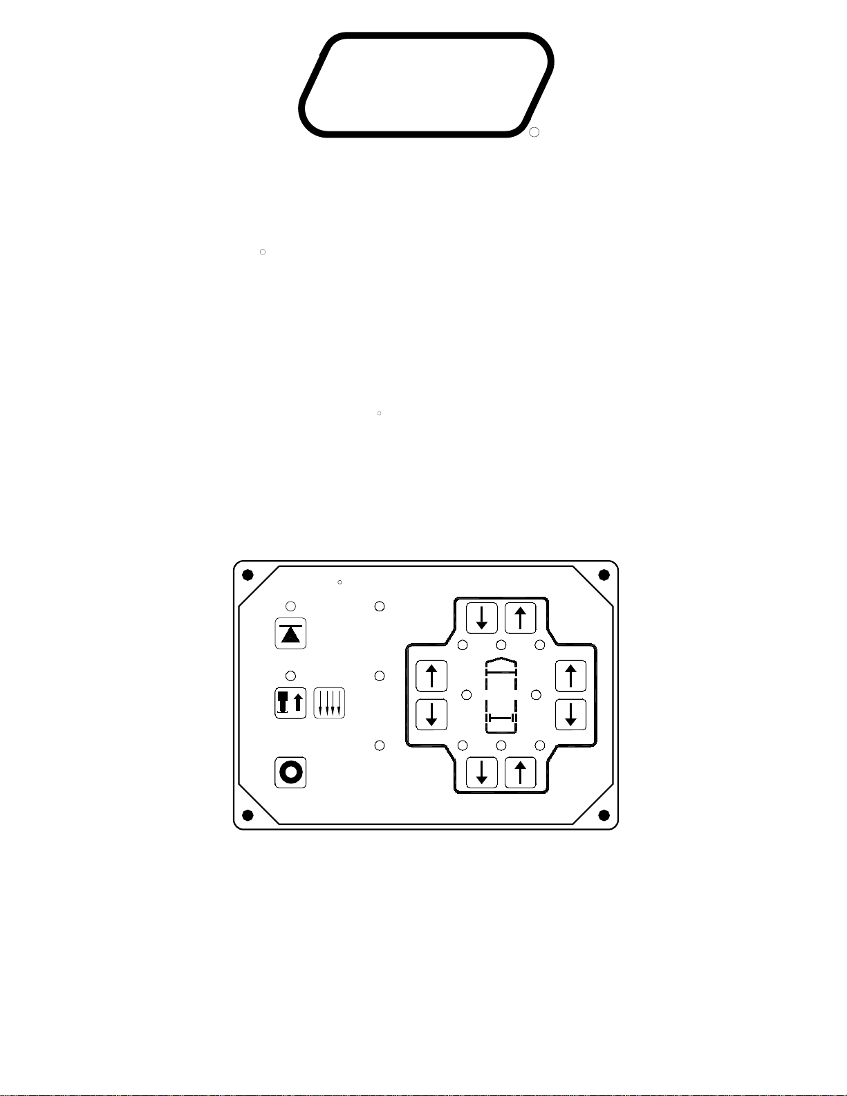
3. Press the "AUTO LEVEL" button one time.
The AUTO LEVEL light will start to flash. Systems
The system will automatically extend the jacks to level the
vehicle and then extend any remaining jacks for stabilizing.
After the system has finished leveling and stabilizing, it will
automatically shut off.
5. Turn the ignition switch to the "OFF" position.
JACK RETRACTION
OPERATING PROCEDURES
625 SERIES LEVELING SYSTEM
support the vehicle.
EXCESS SLOPE SITUATION: In the event the jacks are
unable to level the coach, the "EXCESS SLOPE" light will
come on. Excess slope is two jacks fully extending without
turning the yellow level light out. The system will not stabilize
the vehicle if the "EXCESS SLOPE" light comes on. One or
more jacks may not be extended. The system will shut off
leaving the "EXCESS SLOPE" light on. The "EXCESS
SLOPE" light will remain on if the ignition is in the "ON" or
"ACC" position, until the jacks have been fully retracted
turning the red warning lights out. Push the "STORE" button
to retract the jacks. Move the vehicle to a more level position
or level the vehicle as close as possible according to the
MANUAL HYDRAULIC OPERATION section.
IMPORTANT: During the Automatic Leveling
procedures, pushing the "AUTO LEVEL",
"AUTO STORE" or the "EMERGENCY STOP"
button on the HWH touch panel will stop the
air from the vehicle suspension. After approximately 25
equipped with HWH operated dump will begin to dump
CAUTION:
PERSONS AND OBJECTS ARE CLEAR OF THE VEHICLE.
BUTTON THE OPERATOR MUST BE SURE THAT ALL
PRIOR TO PUSHING THE "AUTO LEVEL"
operation and inhibit proper leveling of the vehicle.
the vehicle engine during leveling can cause erratic
NOTE: If the vehicle has an air suspension, running
NOTE: If the vehicle is equipped with an air suspension
and a manual pilot dump, the suspension air should be
exhausted at this time. Refer to the vehicle manufacturer
for operating instructions.
seconds, the leveling process will begin.
automatic leveling function.
thermal expansion.
automatically retract any jack that extends due to
has been used to retract the jacks, the system will
a jack to extend slightly. When the "STORE" button
NOTE: When traveling thermal expansion may cause
1. Start the engine. Store the jacks immediately.
"WARNING" lights condition.
to store for thirty minutes, then shut down regardless of the
red "WARNING light does not go out, the system will continue
the four individual red "WARNING" lights are out. If any one
out. The system will automatically shut down six minutes after
flash. As each jack retracts, its red WARNING light will go
2. Press the "STORE" button. The store indicator light will
ALL PEOPLE ARE CLEAR OF THE VEHICLE.
THERE ARE NO OBJECTS UNDER THE VEHICLE AND THAT
IMPORTANT: DO NOT interrupt power to the leveling
CAUTION:
THE OPERATOR MUST BE SURE THAT
while traveling, the jacks should be checked as soon as
IMPORTANT: If a red warning light and buzzer come on
THE STORE/TRAVEL POSITION AND THE VEHICLE IS AT
are inflated to the vehicles proper ride height.
the green "TRAVEL" light is on, and the suspension air bags
lights are out, the jacks are in the STORE/TRAVEL position,
3. The vehicle can be moved as soon as the red warning
CHECK THAT ALL JACKS ARE FULLY RETRACTED INTO
WARNING LIGHTS. IT IS THE OPERATOR’S RESPONSIBILITY TO
CREATE A DRIVING HAZARD. DO NOT RELY SOLELY UPON
SEVERE DAMAGE TO THE JACKS AND OR THE VEHICLE AND
WITH THE LEVELING JACKS EXTENDED CAN CAUSE
WITH STRAIGHT-ACTING JACKS. MOVING THE VEHICLE
OR IN THE EXTEND POSITION. THIS VEHICLE IS EQUIPPED
LEVELING JACKS ARE STILL IN CONTACT WITH THE GROUND
DO NOT MOVE THE VEHICLE WHILE THE
a safe parking location is found.
THE PROPER RIDE HEIGHT.
CAUTION:
The system must be allowed to completely finish the
DO NOT push the "OFF" button or turn the ignition key.
system while the "STORE" indicator light is blinking.
4. If jacks cannot be retracted by the above procedure see
MANUAL JACK RETRACTION Section.
STORE mode.
NOTE: If the vehicle is equipped with an air suspension
and a manual pilot dump, place the suspension in the
TRAVEL position at this time. Refer to the vehicle
manufacturer for operating instructions.

OPERATING PROCEDURES
MP34.3012
09MAR07
IMPORTANT: Do not continue to push an EXTEND
MANUAL HYDRAULIC OPERATION
1. Place transmission in the recommended position for parking
2. Place pads under the jack feet if the ground will not support
the vehicle on the jacks.
4. The vehicle may be leveled using the manual EXTEND
(UP ARROW) buttons on the right half of the panel. If a yellow
LEVEL SENSING light is on, that side or end of the vehicle is
Jacks will extend (or retract) in pairs to raise (or lower) a side
or end of the vehicle. Any jack not used for leveling can be
extended to the ground. This provides additional stability
button for more than ten (10) seconds after that pair of
5. When leveling is completed, turn the ignition switch
to the "OFF" position.
against wind and activity in the vehicle. Jacks used to
the vehicle, and set the parking brake. Turn the ignition to the
"ACCESSORY" position.
jacks are fully extended.
3. If applicable, push the "DUMP" button. Wait until all of
the air is exhausted from the vehicles suspension system.
when manual operation of the leveling system is used.
IMPORTANT: Push the "STORE" button before traveling
stabilize the vehicle after leveling is complete should lift the
vehicle slightly after touching the ground.
low. It is best to level the vehicle side to side first, if needed,
before front to rear.
NOTE: if the vehicle is equipped with a manual pilot air
dump, the air must be exhausted from the suspension
before leveling. Refer to the vehicle manufacturer for
instructions.
If necessary, hold the button to exhaust the air.

OPERATING PROCEDURES
MP34.3302
07MAR07
MANUAL JACK RETRACTION
been opened far enough to allow the jacks to retract.
the T-Handle will turn harder. Make sure the valves have
will turn several turns easily. As the valve starts to open,
Large style with T-Handle valve release:
power unit. The upper most manifold should control
NOTE: Multiple manifolds may be present on the
retract the jacks.
if the STORE feature on the HWH control panel will not
Use the manual valve release for retracting the jacks only
DO NOT CRAWL UNDER THE VEHICLE, KEEP A SAFE
DISTANCE IN FRONT AND REAR OF THE VEHICLE.
THE VEHICLE MAY DROP AND/OR MOVE FORWARD
OR BACKWARD WITHOUT WARNING AS THE VALVE
RELEASE IS OPERATED.
1. Locate your power unit-manifold assembly.
2. Allow clearance for the vehicle to lower.
CAUTION:KEEP AWAY FROM THE WHEELS,
point as internal damage may occur to the solenoid.
incorporated into the Breather Cap. Before using read
NOTE: As of APRIL 2002 a 1/4" Nut Driver has been
and understand the last page of this manual.
6. Check that all jacks are now retracted. If yes, continue.
7. Close the valves by turning each valve release clockwise.
DO NOT tighten the manual valve release past this
IMPORTANT: Once the manual valve release is snug,
8. The system should now be repaired before using again.
3. Using the diagram below identify the style
5. Repeat the process by identifying then opening
the two outer valves, if applicable.
LARGE STYLE
WITH T-HANDLE
VALVE RELEASE
SMALL STYLE
WITH VALVE
RELEASE NUT
LARGE STYLE
RELEASE NUT
WITH VALVE
PLASTIC PLUG
BREATHER
CAP
Small style with Valve Release Nut: DO NOT
1/4" valve release nut more than . Turning
the nut more could damage the valve.
release nut is located under a plastic plug that must be
removed to gain access.
could damage the valve.
Large style with Valve Release Nut:
The T-Handle
The 1/4" Valve
turn the
DO NOT turn the 1/4" valve
release nut more than . Turning the nut more
jack functions. (Valve styles and arrangements will vary)
POWER UNIT-MANIFOLD ASSEMBLY
MANIFOLD
of your two center valves.
If no, notify the dealership where you purchased the vehicle
or had the leveling system installed or contact
(The diagram below represents a typical Power Unit-
MANUAL JACK RETRACTION
extensions are fully retracted prior to performing
IMPORTANT: HWH recommends that all HWH room
manual jack retraction procedures.
Manifold Assembly it may not be an exact match to yours).
4. Retract the front jacks by opening the two center valves.
Slowly turn the manual valve releases counter clockwise
until the jacks start to retract.
1 full turn
4 and 1/2 turns
HWH Corporation customer service.

MP44.0001
26FEB07
MAINTENANCE
All major components of the system can be replaced
with rebuilt parts or can be sent to HWH CORPORATION to
be rebuilt, when the system is out of warranty.
UNUSUAL CONDITIONS
OIL LEVEL
ELECTRICAL SYSTEM
The batteries should be in good condition and fully charged.
Weak batteries can cause erratic operation. Battery cable
terminals and battery posts and connections should be kept
clean.
All electrical connections, especially ground connections,
should be clean, tight, free from corrosion and protected
from weathering.
OPERATIONAL CHECK
Review the operator manual and run the system in the
automatic and manual mode. Note any abnormal operation.
Check that the vehicle is level when all the yellow LEVEL
indicator lights are out.
Review the JACK RETRACTION Section.
Check the air dump system by using the manual "DUMP"
button according to the MANUAL AIR DUMP section. If the
system will not dump air or return to the proper ride height,
contact your dealer or HWH Corporation.
NOTE:
Contact you dealer or HWH Corporation for assistance.
It is important that the four leveling jacks are fully retracted
before checking the hydraulic oil level. To check the oil
supply, remove the breather cap from the top of the hydraulic
oil reservoir. The oil level should be approximately one inch
below the top of the reservoir when adequately filled.
FLUID: HWH Specialty Hydraulic Oil is recommended. In an
brake fluid or hydraulic jack fluid. Use of these can damage
and can cause staining should a leak occur. DO NOT USE
Dexron automatic transmission fluid contains red dye
emergency Dexron automatic transmission fluid can be used.
seals.
NOTE:
If driving conditions are unusually muddy, the jacks may
become caked or clogged with mud. This condition may
hamper the proper operation of the leveling system. This
problem may be prevented or remedied by cleaning off each
leveling jack if they become excessively muddy.
In wet or icy weather leveling jacks may become encrusted
with ice. This may cause the leveling system to function
improperly. To eliminate this problem, periodically check the
leveling jacks and break loose any ice which may be
causing improper operation.
Do not move the vehicle while the leveling jacks are still in
contact with the ground. Retract the jacks according to the
"JACK RETRACTION" section and then visually check to
see if the leveling jacks have returned to the
STORE/TRAVEL position.
Check that all lights work according to the INDICATOR
LIGHT section. Correct function of the four red WARNING
lights is essential to the correct operation of the system.
Make sure the jacks will fully retract to the store position.
Jacks should not interfere with any part of the vehicle when
in the store position.
With the jacks extended, check that the jacks can be
retracted using the "T" handles on the solenoid valves.
Refer to the MANUAL JACK RETRACTION section.
NOT IN PARK/BRAKE LIGHT CHECK
1. Turn the ignition on.
2. Set the park brake.
3. Turn the leveling system on.
4. Apply the foot brake or chock the wheels so the
vehicle cannot move.
5. Release the park brake. The Leveling System panel
should turn off.
6. Apply the park brake.
7. If the panel does not turn off when the park brake is
released, the system needs to be checked.

MAINTENANCE/SERVICE
SENSING UNIT ADJUSTMENT
Level the vehicle by placing a bubble level in the center of
the freezer floor or upon whichever surface within the vehicle
that is to be level. Using the Leveling System and the bubble
level, ignoring the yellow LEVEL lights on the Touch Panel,
level the vehicle until the bubble is centered.
The Sensing Unit is mounted inside the Control Box. The
Control Box is mounted to the power unit/valve assembly.
NOTE: If opposing LED’s are lit, there is a problem with
the Sensing Unit.
If LED (A) is lit: Turn the adjustment screw COUNTER
CLOCKWISE until the LED is off.
If LED (C) is lit: Turn the adjustment screw CLOCKWISE
until the LED is off.
If LED (B) is lit: Turn the adjustment nut COUNTER
CLOCKWISE until the LED is off.
until the LED is off.
If LED (D) is lit: Turn the adjustment nut CLOCKWISE
ADJUSTMENT
NUT (5/16")
TOP VIEW - SENSING UNIT
ADJUSTMENT
NUT ADJUSTMENT SCREW
D
C
A
B
CONTROL
BOX WALL
LED’S - LOCATION SIDE VIEW - CONTROL BOX
MAY BE DIFFERENT
07MAR07
MP44.1500
There are four LED’s on the Sensing Unit, A,B,C and D. Refer
to the drawing below. The Sensing Unit is adjusted by turning
the adjustment nut to turn out LED’s B and D. The adjustment
screw will turn out LED’s A and C. If the adjustment nut has
to be turned more than 1/2 flat or the adjustment screw has to
be turned more than 3/4 turn to turn the LED out, there may
be a problem with the Sensing Unit or the mounting of the
Control Box. If two LED’s are on, it is best to make the B-D
adjustments first, then hold the adjustment nut from moving
ADJUSTMENT NUT
while making the A-C adjustment.
ADJUSTMENT
SCREW (Phillips or 1/4")
NUT (7/8" or 3/4")
ADJUSTMENT
With the vehicle level according to the bubble level, if there
are no yellow lights lit on the Touch Panel, the sensing unit is
properly adjusted. If there are yellow LEVEL lights lit on the
Touch Panel, manual adjustments to the Sensing Unit are
needed. A 7/8", 3/4" or 5/16" socket w/driver or box end
wrench and a philips screw driver will be needed.
IMPORTANT: When all 4 LED’s are off, move the
vehicle to an unlevel position so one or two yellow
lights are on. Level the vehicle according to the yellow
LEVEL lights. Recheck the level. If more adjustment is
needed, DO NOT try to adjust the sensing unit until the
yellow level lights go out, instead just "tweak" the
sensing unit, ignoring the LED’s on the sensing unit.
Example: After the initial adjustment and releveling
the vehicle, the front is still low. This means the front
yellow level light is turning off too soon. Determine
which sensing unit light is the front light, A-B-C or D.
Move the adjustment for that light very, very, slightly in
the OPPOSITE direction that is given in the above
instructions for LED’s A, B, C, and D. This will allow
the front yellow light to stay on slightly longer to bring
the front up more. Again, unlevel the vehicle then
relevel the vehicle using the yellow level lights on the
touch panel. Recheck with a level. Repeat the
"tweaking" process until the system levels the vehicle
properly.

BREATHER CAP - DIPSTICK - 1/4" NUT DRIVER
MP84.9999
07FEB07
VALVE RELEASE
NUT 1 1/2" DIAMETER
SOLENOID VALVE
NOTE: DO NOT turn the valve
release nut more than 4 and 1/2
(four and one half) turns counter
clockwise. Damage to the valve
may result.
OIL LEVEL
BREATHER CAP
OIL LEVEL GROOVES
1/4" NUT DRIVER
NOTE: THE BREATHER CAP IS LOCATED
ON THE TOP SIDE OF THE POWER UNIT RESERVOIR.
IMPORTANT: PRIOR TO REMOVING THE BREATHER CAP,
EITHER TO CHECK THE OIL LEVEL OR TO USE THE 1/4" NUT DRIVER,
CLEAN ANY DEBRIS FROM THE TOP OF THE RESERVOIR.
INCLUDING DEBRIS INSIDE THE 1/4" NUT DRIVER.
REMOVE ANY PAINT CHIPS OR OTHER DEBRIS FROM THE DIPSTICK
BEFORE RETURNING THE BREATHER CAP TO THE RESERVOIR,
VALVE RELEASE
NUT
to the valve may result.
turn counter clockwise. Damage
NOTE: DO NOT turn the valve
release nut more than 1 full
PLASTIC PLUG
REMOVE TO
GAIN ACCESS
TO THE 1/4"
VALVE RELEASE
NUT
SOLENOID VALVE
2 1/4" DIAMETER
Other manuals for 625 Series
9
Table of contents
Other HWH Automobile Accessories manuals
Popular Automobile Accessories manuals by other brands

Code 3
Code 3 SuperVisor user guide

Spyder Auto
Spyder Auto PRO-YD-CCO04 Series installation guide

Metra Electronics
Metra Electronics 99-6502 installation instructions

AA Products
AA Products SR-A260 instruction manual

Fortin
Fortin KEY-OVERRIDE-SL2 installation guide

Thule
Thule Rapid 1458 Fitting instructions

FVC
FVC Sprinter Bed System Flarespace installation guide

Telit Wireless Solutions
Telit Wireless Solutions Sat 550 Installation and operation guide

LAS
LAS High Power WHEEL CLAMP quick start guide

NSV International
NSV International Toyota Tundra Lightbar manual

Mont Blanc
Mont Blanc MB RoofBar Flex 02 Fitting instructions

Pyle
Pyle PLCM2720 user manual