- 4 -
3. Wiring Power to the Wireless LED Display
There are two methods for powering the wireless LED display:
a) Method [1]: The wireless display comes with attached power cable and a cigarette lighter
type plug. Simply Insert the plug into the cigarette lighter jack.(Fig. 4).
b) Method [2]*: If you want to route and hide the power cable of the display, you may cut off the
cigarette lighter type plug from the power cable, and wire the cable directly to ACC or "ON"
block of the ignition switch. Strip 1" of the wires. Connect the red wire to +12V and the black
wire to (-) negative or chassis ground. Wrap the connections with vinyl electrical tape.
*Note: although the power wires of the display can be cut off for more flexible
installation, display with its power wires cut off voids warranty on it.
4. Wiring Power to the Control Box
a) Insert the 3-pin plug of the power cable of the control box into its socket labeled PWR on the
side of the main control box (Fig. 3).
b) Locate the +12V and the (-) negative wires from the back up light near the taillight assembly.
If necessary, remove the taillight assembly to locate them.
c) Strip 1/2" of the wires found.
d) Connect the red wire of the power cable to the +12V wire (Fig. 3)
e) Connect the black wire of the power cable to the (-) negative or chassis ground (Fig. 3).
f) Wrap the connections with vinyl electrical tape.
5. Installing the Sensors
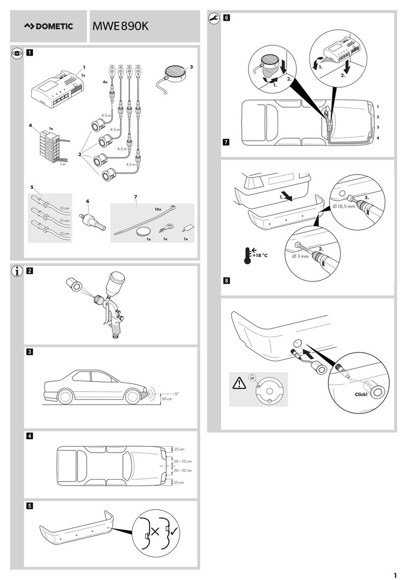
IMPORTANT: (a) To avoid false alert from the system detecting the ground, the sensors should
be mounted between 50cm to 80cm (20" to 32") above the ground and the face of the sensors
need to be vertical or slightly upward angled (Fig. 2). (b) Horizontally, the sensors should be
equally spaced if possible or symmetric to the center of the bumper. (c) The outer two sensors
should be mounted about 15cm (5.9") from the corner of the bumper for better corner coverage.
Note: The bumper surface for mounting the sensors should be as flat and vertical as possible.
For exact color match, you may have the sensors spray-painted. For best results, spray paint
no more than two thin coats (not to be applied with brush or touch-up). And it is recommended
that you have the sensors professionally painted by an auto body shop.
Note: although the sensors can be spray-painted for exact color match to your vehicle,
sensors painted void warranty on them.
a) Refer to Fig. 1 for mounting height and positioning of the sensors.
b) Work under the rear bumper to check the internal structure of it before marking the positions
for drilling holes. You may need to remove the bumper if the view is blocked,.
c) With chalk or marker, mark the position of sensors on the rear bumper. Make sure that the
sensors can be pushed all the way in and that you can feed the wires through.
d) Drill the holes through the bumper at the marks with the Φ21mm drill bit included. Note: if
drilling through metal bumper, use a bi-metal Φ21mm (13/16") drill bit (not included).
e) If necessary, smooth the sharp edge of the holes with a polishing head or small round file.
f) If you have a non-vertical bumper, you may need to use the wedge-shaped plastic sensor
spacers provided. Carefully push each sensor into its sensor spacer to avoid breaking it.
g) Run the sensor wires into the holes drilled. Push the sensors into the holes. Note: When
pushing in the sensors only apply pressure at the edges, not on the middle of the sensor to
avoid damage to the sensor element. The sensors are tapered for a snug fit.
h) Run the sensor wires from the bumper into the trunk or inside of the vehicle through the
existing small vent or rubber grommet in the rear of the trunk or vehicle, and to the control
box. Note: Do not cut the sensors wires.
i) Attach sensor wires to the vehicle body with cable/wire ties so that they will not get in the
way of any moving parts and there are no loose wires hanging down.
j) Plug one sensor at a time into its corresponding socket at the control box, start the engine
and put the vehicle in reverse, the display should show the correct obstacle distance. Repeat
the procedure for the remaining sensors.
