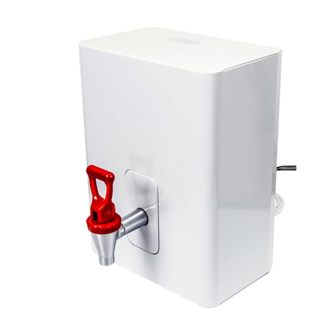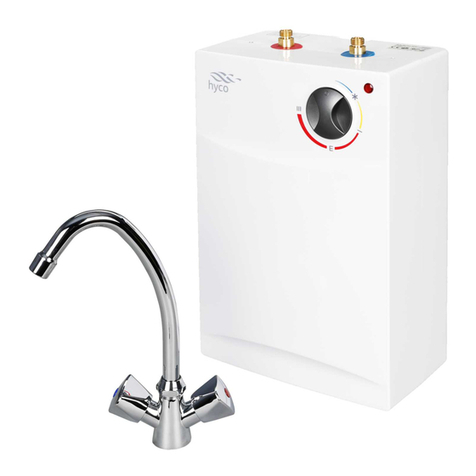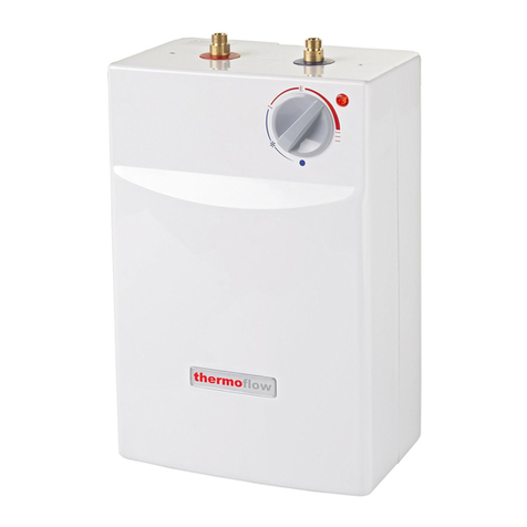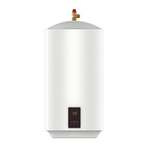
2
4 SITE REQUIREMENTS
4.1 WARNING - The hand wash must not be positioned where it may be subjected to freezing conditions.
4.2 Water requirements. The installation must be in accordance with Water Regulations. To ensure activation of the heating elements, the
hand wash must be connected to a water supply with a minimum running pressure of 1 Bar (14.5 psi) ands a maximum static pressure of 3
Bar (45 psi). If in doubt, the pressure should be checked taking into account of other services from the mains water supply which could
cause the pressure to fall below the minimum. The water supply can also be taken from a cold water storage cistern provided there is a
minimum head of 10m above the unit. It must be an independent supply to the hand wash only.
4.3 If the hand wash is operated outside of the stated pressure parameters, it may not be possible to achieve optimum performance from the
unit throughout the year.
ELECTRICAL REQUIREMENTS
4.4 WARNING - THIS APPLIANCE MUST BE EARTHED
4.5 IMPORTANT The installation, supply cable and circuit protection must conform to BS7671.
4.6 Before making any sort of electrical connection ensure that no terminal within the circuit is live. If in any doubt, SWITCH OFF the whole
installation at the consumer unit.
4.7 The hand wash must only be connected to a mains supply not exceeding 240 Volt ac supply.
4.8 The earthing and protective conductor arrangement within the property, in particular the supplementary bonding in the room containing the
hand wash, shall comply with BS7671.
4.9 Ensure that the supply cable and fuse are sufficient for the rating input of your unit. Please refer to the rating label on the unit.
4.10 A minimum cable size of 1.5 sq. mm must be used. The hand wash can be connected in two different ways:
a) Via a fused and switched connection unit taken as a spur from a 13 Amp ring main
b) As a separate circuit taken directly from a spare way in a consumer unit.
In each case, a double pole isolating switch having a contact separation of at least 3mm in each pole and a minimum rating of 13 amp must be
incorporated in the wiring to the unit.
5. CONSIDERATIONS BEFORE FITTING
IMPORTANT
5.1 The unit must be mounted on a flat surface, which covers the full width and length of the back plate. It is important that the wall surface is
flat, otherwise difficulty may be encountered when fitting the cover.
5.2 Ensure that the hand wash is positioned over the basin because if the pressure relief device operates, water will eject from the bottom of the
unit.
5.3 The outlet of the hand wash acts as a vent and MUST NOT be connected to any form of outlet or any other fitting.
5.4 DO NOT fit the hand wash to the wall and tile up to the case. It must be fitted to a flat and even wall surface. This allows removal for
servicing.
5.5 The control knob is an integral part of the cover - do not attempt to remove it.
5.6 Position the unit on the wall so that the spray will be contained within the basin, and at a convenient height for hand washing
5.7 It must not be installed for use as a shower unit, or in an area where the unit may be subjected to direct spraying .
5.8 A clearance of at least 130mm above and below the unit should be allowed for access to the cover screws.
5.9 Cable entry - can be from the rear (preferred) or from the side. The back plate has a cut-out position to suit the size of cable.
6.0 Pipe Entry. Plumbing entry is from the bottom.
6 FITTING INSTRUCTIONS
6.1 TURN OFF water and electrical supply
6.2 Unscrew the retaining screw on the cover base and lift the cover from the back plate
6.3 Fit the outlet spout DO NOT over tighten - finger tight will be sufficient
6.4 After choosing the correct site for the hand wash, use the back plate as a template and mark the two fixing holes. See 5.1 to 5.7
6.5 Drill holes using 6.5mm diameter masonry drill - BEWARE OF CABLES AND PIPES THAT MAY BE BURIED IN THE WALL
6.6 Use plugs to suit wall and fixing screws supplied
6.7 PIPE CONNECTION. The outlet pipe can be removed to ease installation
6.8 The hand wash has been designed for a 15mm water pipe, fitted to the blue (cold water) inlet by the compression type tap connector to suit
a 15mm pipe.
6.9 Decide where to connect the cold water supply mains feed to the unit. Ensure the pipe you have selected is not a gas pipe or hot water
pipe.
6.10 An isolating stop valve MUST be incorporated to the main water supply to comply with water regulations - see fig 4.
6.11 Cut all necessary pipe work to length with a pipe cutter, not a hacksaw to minimise swarf.
6.12 Assemble the installation before making any soldered joints to ensure that the pipe is the correct length. DO NOT use jointing compounds
on any pipe fittings for the installation
6.13 It is essential to flush the pipe in order to clear debris and swarf.
6.14 Turn the water off after flushing using the isolating stop valve.
6.15 Connect the cold water supply (marked blue on the unit) to the heater inlet, using the tap connector fitting.
6.16 Fit top and bottom screws and secure the back plate to the wall, ensuring it is level.
6.17 Close the hand wash flow control valve by turning the knob fully anticlockwise.
6.18 Turn on the isolating stop valve on slowly, and check for leaks in the pipe work, and rectify where necessary.
6.19 Turn off the isolating stop valve.
7 ELECTRICAL CONNECTIONS
7.1 WARNING - THIS APPLIANCE MUST BE EARTHED
7.2 CAUTION!! When working on electrical appliances, ensure they are NOT LIVE. If in any doubt, SWITCH OFF THE ELECTRICITY
SUPPLY AT THE MAINS.
7.3 A double-pole isolating switch having a contact separation of at least 3mm in each pole MUST be incorporated in the circuit - see
paragraphs 4.10 and 4.11
7.4 The cable entry should have been decided before fitting the back plate - see 5.8
7.5 Remove the screw and clamping bar from the cable clamp.
7.6 Feed the cable into the back plate (unscrew the back plate for easy feeding if necessary).
7.7 Strip the outer sheath of the cable to a point about 5mm above the clamp, thus ensuring that the cable is clamped across its outer sheath.
7.8 Strip the insulation from the cores and make connections : Red/Brown to “L” Live terminal;
Black/Blue to “N” Neutral terminal


