4”–12” Insta-Valve 250 | Installaon Instrucons | 7
© 2021 Hydra-Stop | All Rights Reserved. | Specicaons subject to change without noce.
2.3.8)
2.3.9)
NOTE:
2.3.10)
2.3.11)
2.3.12)
2.3.13)
2.3.14)
NOTE:
2.4.0 Installing the Hydra-Tapper
2.4.1)
NOTE:
2.4.2)
2.4.3)
NOTE:
NOTE:
NOTE:
2.4.4)
2.4.5)
• 6” core sample: 3.5”
• 8” core sample: 3.5”
2.4.4)
2.4.5)
2.4.6)
NOTE:
2.4.7)
2.4.8)
2.5.0 Performing the Core Sample
2.5.1)
2.5.2)
GPM at 1800 PSI.
2.5.3)
NOTE:
2.5.4)
NOTE:
2.5.5)
2.5.6)
2.5.7)
2.5.8)
2.5.9)
2.5.10)
2.5.11)
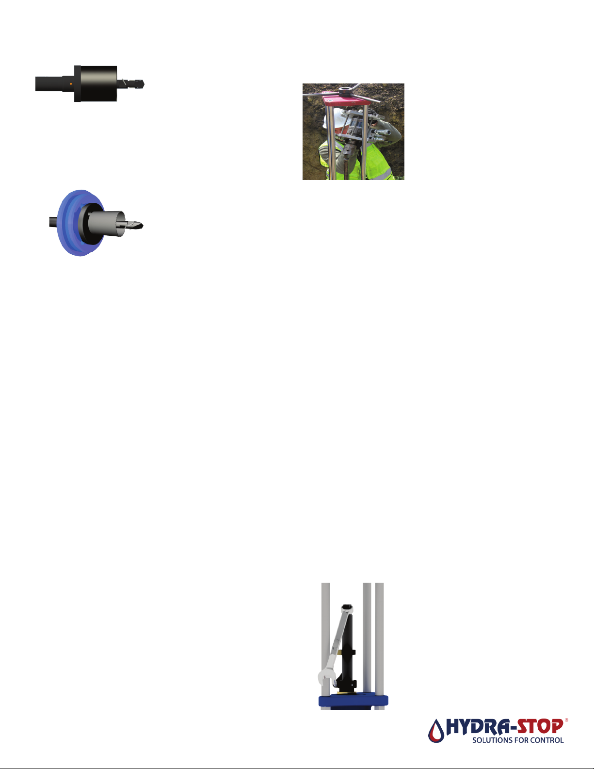
Figure 10
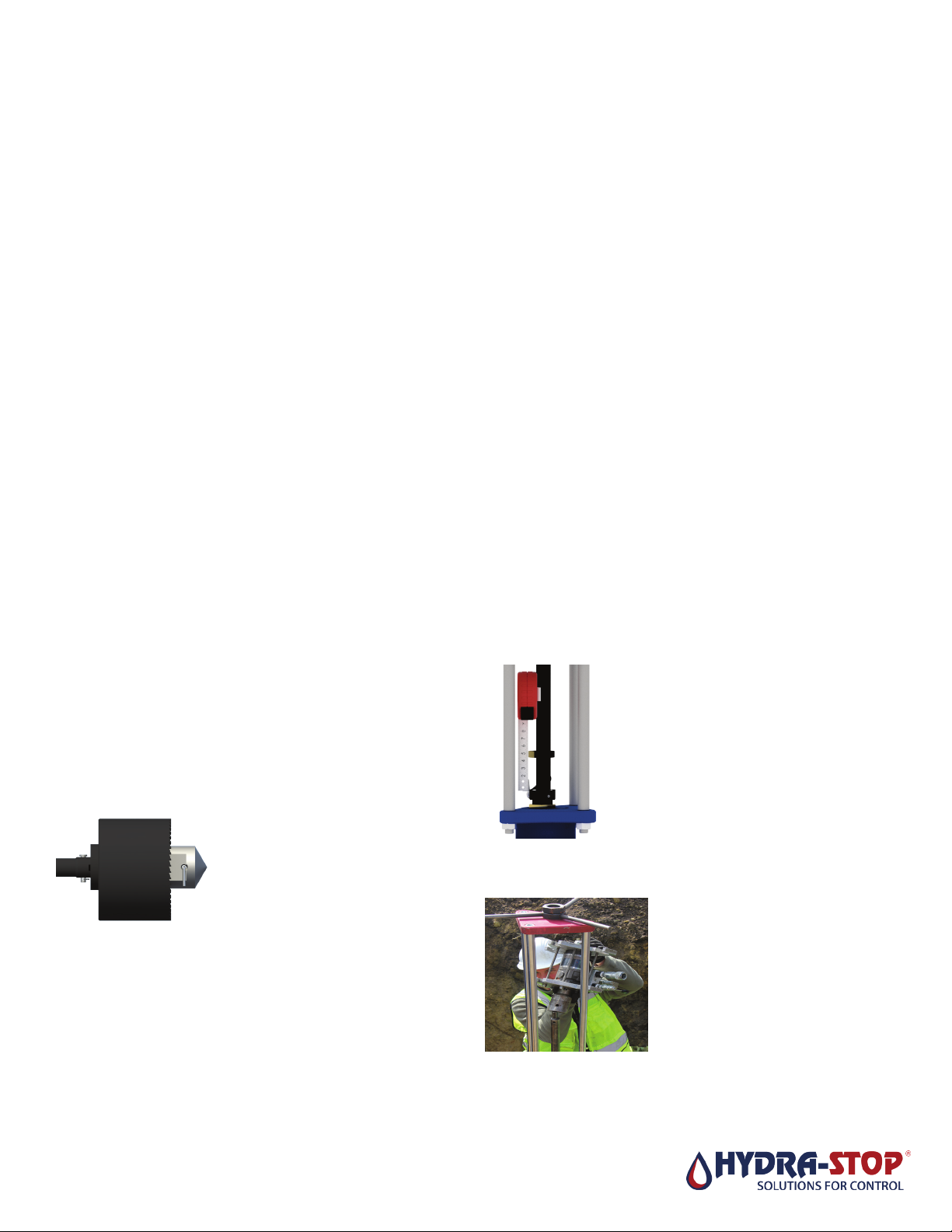
Figure 11
Figure 12
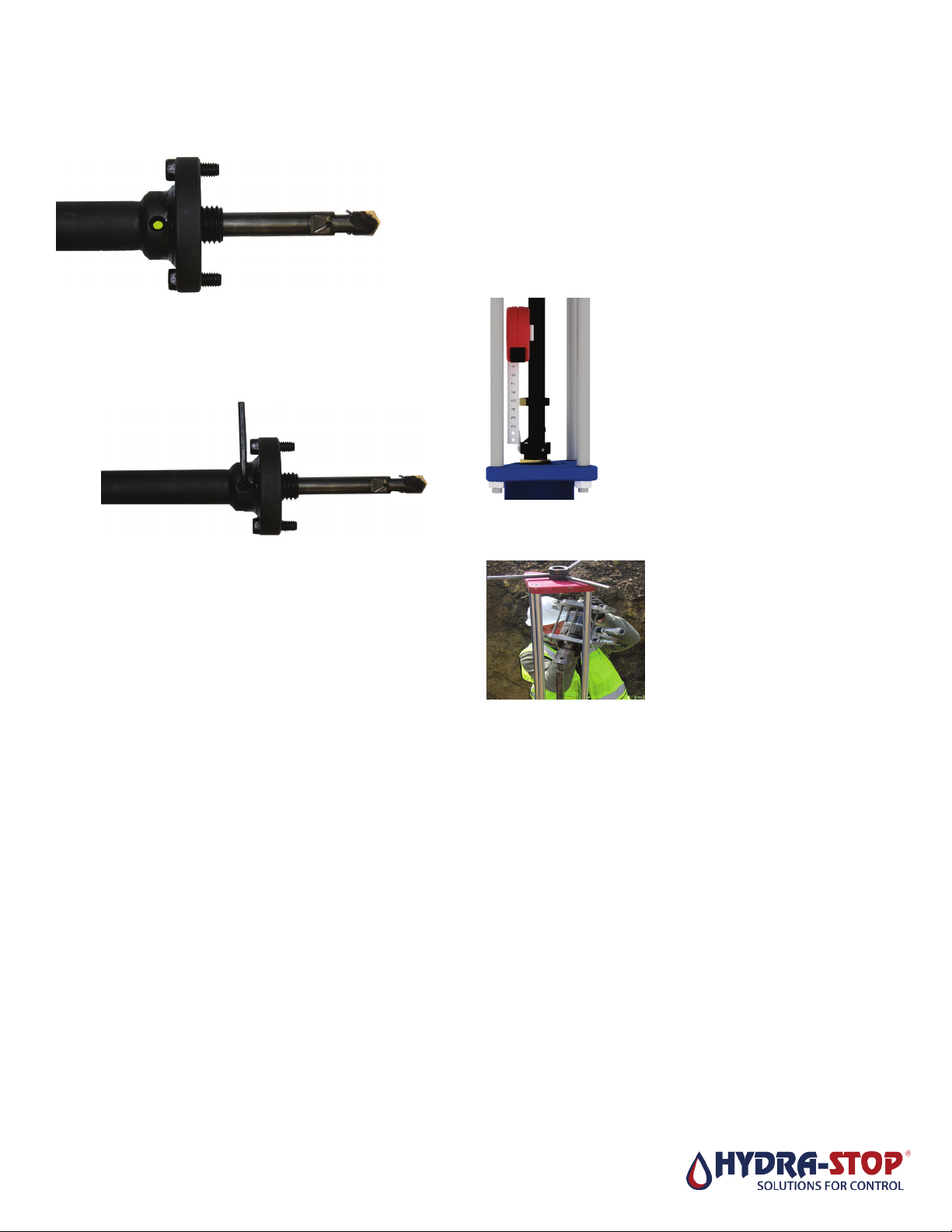
Figure 13