Hydra ECHO Quick guide

ECHO
AC Wall-Mounted EV charger
ELECTRIC VEHICLE CHARGER
INSTALLATION AND INSTRUCTION MANUAL

✆
01268 205 121
| www.hydraev.co.uk | sales@hydraev.co.uk
2
CONTENTS
SAFETY ...................................................................................................................................................................................3
Safety Identication .......................................................................................................................................................3
INTRODUCTION.....................................................................................................................................................................6
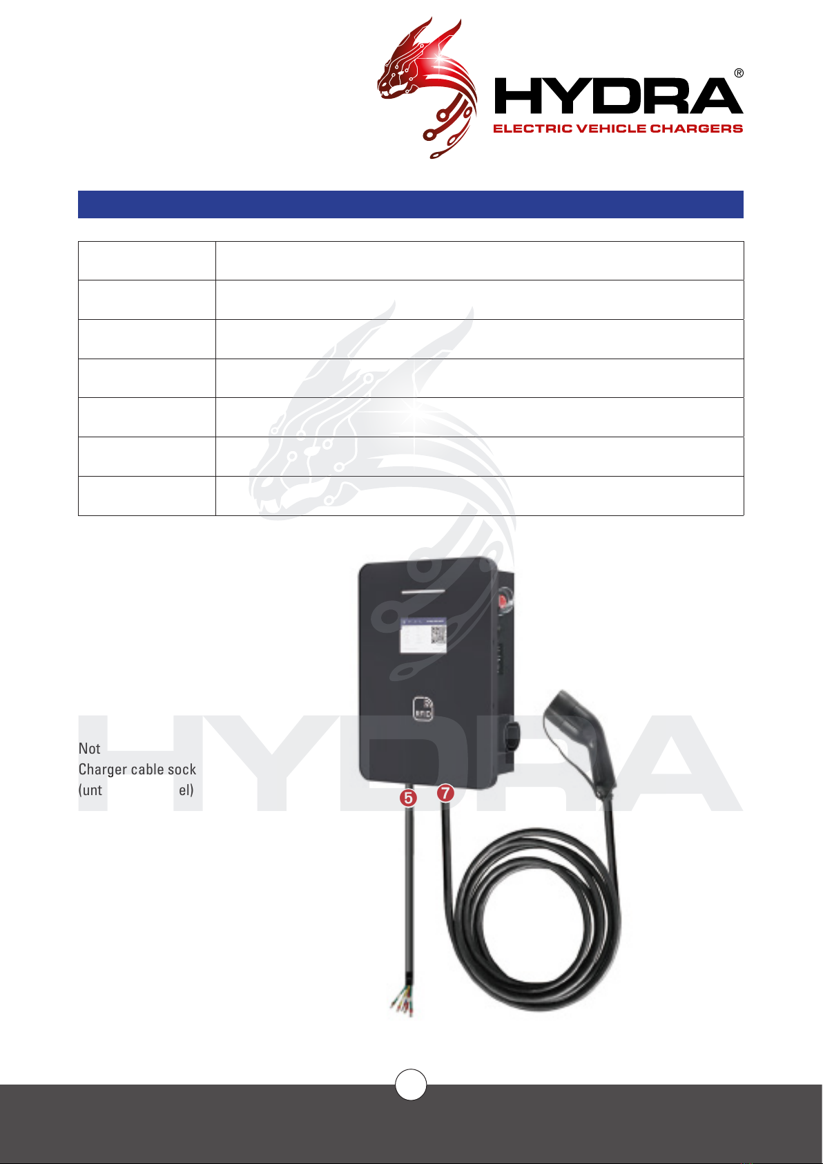
Appearance .....................................................................................................................................................................6
Technical Specications................................................................................................................................................7
Technical Specications (Continued)..........................................................................................................................8
Product Features.............................................................................................................................................................9
INSTALLATION ....................................................................................................................................................................10
Procedure.......................................................................................................................................................................10
Network connectivity requirements ..........................................................................................................................11
Tool preparation ............................................................................................................................................................12
Socket and Tethered.....................................................................................................................................................13
Internal Structure..........................................................................................................................................................14
Product Parameter .......................................................................................................................................................15
List of Products and Accessories ..............................................................................................................................16
Site Space Requirements ............................................................................................................................................17
Installation Instructions ...............................................................................................................................................18
Electrical Requirements...............................................................................................................................................19
Installation Step 1 .........................................................................................................................................................20
Installation Step 2 .........................................................................................................................................................21
Installation Step 3 .........................................................................................................................................................22
Installation Step 4 .........................................................................................................................................................23
Installation Step 5 .........................................................................................................................................................24
AFTERSALES........................................................................................................................................................................25
Aftersales Service ........................................................................................................................................................25
Disclaimer ......................................................................................................................................................................25
Maintenance..................................................................................................................................................................25
Procedures.....................................................................................................................................................................25
During Installation.........................................................................................................................................................26
After Installation............................................................................................................................................................26
PROCEDURES ......................................................................................................................................................................27
APPENDIX............................................................................................................................................................................28
Fault Diagnostics...........................................................................................................................................................28

✆
01268 205 121
| www.hydraev.co.uk | sales@hydraev.co.uk
3
SAFETY
SAFETY ANNOUNCEMENTS
Before operating the EV charger, read the instructions and precautions carefully to reduce the risk of accidents.
The “caution, warning, hazard” notices in the product and product manual do not represent all safety concerns
to be observed and are only intended to supplement the various operational safety precautions.
In carrying out the company’s product and equipment operations, you must comply with relevant industry safety
norms and strictly abide by these instructions to provide the appropriate equipment precautions and special
safety instructions
IDENTIFICATION DESCRIPTION
Indicates that care must be taken with the operation or condition of hazardous voltage
Important security information must be followed very carefully
Indicates risk of burns from high-temperature areas or areas with high
component temperatures
Ground protected connection point
DC electricity
AC electricity
Indicates that the said action must be performed using clothing and/or personal
protective equipment provided by the employer
Type A Residual Current Devices (RCD)
Type B Residual Current Devices (RCD)

✆
01268 205 121
| www.hydraev.co.uk | sales@hydraev.co.uk
4
SAFETY
ELECTRICAL SAFETY
HIGH VOLTAGE
Some components of the power system operate with high voltage. Direct or indirect
contact with these components through non-insulated protective material poses a fatal
hazard.
The installation of AC power supply equipment must comply with safety regulations, and personnel carrying out
the installation of AC equipment must be qualied in high voltage AC-power operation.
It is strictly prohibited to wear watches, bracelets, rings or other conductive objects on your wrist or hand.
Turn off the power immediately if you nd water or moisture in the electric cabinet. When operating in humid
conditions, water should be strictly prevented from entering the equipment.
A “Do not operate” sign must be hung on switches and buttons that are not to be used during installation.
Construction of high-voltage lines can cause re or electric shock accidents.
The racking and wiring of AC cables through the area must comply with the local
regulations and specications. Only personnel qualied for high-voltage and AC
operations can carry out various high-voltage operations.
TOOLS
Special tools must be used for all high AC voltage operations.
THUNDERSTORMS
High AC voltage operations during thunderstorms are strictly prohibited.
Strong electromagnetic elds are produced in the atmosphere during thunderstorms. To avoid lightning
damage to equipment and personnel, do not carry out any operations during thunderstorms.
ELECTROSTATICS
Static electricity generated by the human body can damage electrostatic-sensitive
components on boards such as large-scale integrated circuits (ICs). To prevent static
damage to sensitive components, personnel must wear an anti-static bracelet when in
contact with equipment (hand-held boards, circuit boards, IC chips, etc.). The anti-
static bracelet must be well-grounded on the other end.

✆
01268 205 121
| www.hydraev.co.uk | sales@hydraev.co.uk
5
SAFETY
SHORT CIRCUITS
It is strictly prohibited to short-circuit the power supply system to the positive and
negative poles or to short the non-ground pole to ground during operation. Short
circuits can cause equipment to burn and pose a personal safety hazard.
In addition, the polarity of the cables and interface terminals must be strictly checked when carrying out live
work.
Power distribution operation space is limited. Before any operation, close attention must be paid to the choice
of operating space.
An insulation tool must be used during operation.
When working with electricity, care must be taken to keep your hands, wrists and arms steady, to prevent
accidents from a tool slipping, or from too much movement of a tool or your body.
SHARP CORNERS
When moving equipment by hand, wear protective gloves to prevent cuts.
POWER CABLE
Make sure that the cable label is correct before connecting the cable.
SIGNAL LINE
The signal cable should be tied separately from the power cable and at
least 15mm away.

✆
01268 205 121
| www.hydraev.co.uk | sales@hydraev.co.uk
6
INTRODUCTION
APPEARANCE
Use Car Parks / Public Charging Station
Material Metal housing
Installation type Wall Mounted
Cable layout Bottom
Weight 5-10kg
Cable length 4m
Charging socket Type2
1 Touch Screen
2 Door Lock
3 RFID Card reader
4 LED status lights
5 Power input
6 RJ45 input
7 Charger Output
(tethered)
Not shown:
Charger cable socket
(untethered model)
➊➊
➋➋
➌➌
➍➍
➏➏➎➎➐➐

✆
01268 205 121
| www.hydraev.co.uk | sales@hydraev.co.uk
7
INTRODUCTION
TECHNICAL SPECIFICATIONS
COMPONENT
SPECIFICATIONS
Dimensions 500(H)mm x 370(W)mm x 290(D)mm
Weight 5kg (no cable) -10kg (with cable)
Cable length ≥4.2m/SOCKET
Shell material Aluminium Alloy
Screen 5” LCD touch screen
POWER
CHARACTERISTICS
Input voltage TN-S 240V AC (single phase)
400V AC (three phase) ±10%
Input frequency 50hz/60hz
Rated power 7kW (single phase)
22kW (three phase)
Measurement accuracy ≤±0.5%
Output voltage Same as input voltage
Output current 7kW/22kW-32A
Efciency ≥94%
Factor ≥0.99
DESIGN FEATURES
UI RFID Card Reader, LCD touch screen, Emergency
Stop Button
Standard GB/T, TYPE2 and IEC61851-1/2017
COMMUNICATION
Web interface Wired Ethernet, 3G/4G
OCPP OCPP 1.6J

✆
01268 205 121
| www.hydraev.co.uk | sales@hydraev.co.uk
8
INTRODUCTION
WORKING
ENVIRONMENT
Use Indoor/Outdoor
Operating temperature -30°C ~ +55°C
Operating humidity 5% to 95%
Elevation <2000m
Protection level IP55
Cooling method Ambient air cooling
Ground detection 30mA
Sound level ≤50db (normal input/output power at ambient 25°C)
RoHS Meets the R5 requirements of the RoHS directive
TECHNICAL SPECIFICATIONS (CONTINUED)

✆
01268 205 121
| www.hydraev.co.uk | sales@hydraev.co.uk
9
INTRODUCTION
PRODUCT FEATURES
The HYDRA ECHO AC Charger has a modern design and user-friendly interface, designed for domestic and
workplace use.
SAFETY FEATURES
Hardware protection features:
Overcurrent protection
Overvoltage protection
Over-temperature protection
Emergency stop protection
Lightning protection
Type B RCD
Comprehensive software protection features, providing multiple protections
Meets IEC61851-22 requirements
All components have CE certicates
The SECC controller has gone through the TÜV test
SMART
The terminal charger is connected to the Open Charge Point Protocol platform online
Remote diagnostics, remote upgrades
Compatible with GB/T Type 2 and IEC61851-1/2017
Internal high-precision MID AC meter
Supports simultaneous charging of multiple connectors
The OCPP platform sets the maximum output power according to the time period
Support for credit card Point Of Sale payment (optional)
Support for OCPP1.6-J (later direct upgrade to 2.0)
CONVENIENT
Wireless or wired communication, exible networking
Open communication protocol for sweep charge, swipe charging and API services
Several settings to end the charge
Time limit
Amount of electricity
Auto lled
OPTIONAL FEATURES
Plug&Charge (optional)

✆
01268 205 121
| www.hydraev.co.uk | sales@hydraev.co.uk
10
INSTALLATION
PROCEDURE
SAFETY INSTRUCTIONS
The operating voltage and current inside the charging system are high, and the following regulations should be
observed at all times to ensure personal safety:
1.Chargingsystemsmust only be installedbypersonnel who have beentrainedin,and have sufcient knowledge
of, the charging system. Always follow safety precautions and local safety regulations during installation.
2. To operate inside the charging system, make sure that the charging system is not live. The power input to the
charging system must be disconnected.
3. Distribution cable wiring should be reasonable and protective to avoid accidental contact when operating
power supplies.
VISUAL INSPECTION
Upon product delivery, check that the package is not damaged and that the label is complete and correct. If
there is an issue, immediately inform the carrier and take photos as evidence. At the same time, immediately
contact the manufacturer to discuss the issue.
Only after the goods arrive at the installation site can they be opened and the boxes opened for inspection.
Start by opening the box with the packing slip, taking out the packing list and checking it against each item.
Next, check the serial number of the box, the equipment packaging, the number and type of accessories and
the integrity of all items.
Following the packing list, check that accessories and accompanying documents are complete (refer to the
shipping list) and store the accessories and documents properly.
Carry out a visual inspection to ensure that the product is free of abnormal marks showing collisions, and of
scratches, cracks, dents, rust, breakage, or peeling of paint.
Sign receipt documents, make a record of the situation, keep documents and scan them for archives, or give
them to relevant parties.
ACCESSORY LIST
The packing list comes with the shipping documents.

✆
01268 205 121
| www.hydraev.co.uk | sales@hydraev.co.uk
11
INSTALLATION
NETWORK CONNECTIVITY REQUIREMENTS
The recommended way to connect to the network is to access 4G wireless communication. A SIM card meeting
local networking requirements is required. Make sure the local signal strength is strong and stable; otherwise
a signal amplier must be installed.
If there is no local 4G communication signal, a standard wired internet connection is available. Wired
connections must meet the following requirements:
RJ45 Ethernet
Network cable type: 5e class or greater, 8P plus PE, shielding wire.
It is recommended that the line length is less than 75m. Greater than 75m length requires a customised
engineering solution.
Minimum bandwidth required:
Upstream: 128 kbps
Downstream: 4 Mbps
Demand connection reliability: 99.9%.
For special congurations, please contact us.

✆
01268 205 121
| www.hydraev.co.uk | sales@hydraev.co.uk
12
INSTALLATION
NAME DESCRIPTION QTY
Multimeter Checking the electrical connections and electrical parameters 1
Electric impact drill Drilling 1
Impact drill bit (Ø 14mm) Drilling 2
Tape measure (5m) Measurement 1
Level ruler Measurement 1
Crosshead screwdriver Unpacking 1
Pliers Unpacking 1
Wire Stripper Removing the insulation sheath / jacket 1
Terminal pressure line pliers Pressing the terminals 1
Bevel cutting pliers Cutting the cable 1
Light hammer Unpacking, tapping, adjustment 1
Carrying equipment Moving and hoisting charger 1
PVC tape and sheath Insulation tape and insulation cladding connection 1
Personal protection tools Ensuring the health and safety of operators 1
TOOL PREPARATION
STANDARD TOOLS

✆
01268 205 121
| www.hydraev.co.uk | sales@hydraev.co.uk
13
INSTALLATION
SOCKET
1.LCD Screen
2.Rd
3.LED Light
4.Type2 Socket
5.LAN port
6. E-STOP
TETHERED
1.LCD Screen
2.Rd
3.LED Light
4.Type2 Socket
5.LAN port
6. E-STOP
➊➊
➊➊
➋➋
➋➋
➌➌
➌➌
➍➍
➍➍
➎➎
➎➎
➏➏
➏➏

✆
01268 205 121
| www.hydraev.co.uk | sales@hydraev.co.uk
14
INSTALLATION
INTERNAL STRUCTURE
1. LED Light Bar
2. 4.3 inch screen
3. RFID Card Module
➊➊
➋➋
➌➌

✆
01268 205 121
| www.hydraev.co.uk | sales@hydraev.co.uk
15
INSTALLATION
INTERNAL STRUCTURE
1 Motherboard
2 LAN Port
3 SIM
4 RCD Switch
5 Protective Earth
6 Input Power Wires
7 A+6 leakage insurance
8 LAN Port Extension Cable
9 MID Certied Electric Meter
➊➊
➋➋
➌➌
➍➍
➎➎
➏➏
➐➐
8
9

✆
01268 205 121
| www.hydraev.co.uk | sales@hydraev.co.uk
16
INSTALLATION
PRODUCT PARAMETERS
Product Series Commercial-SINGLE Tethered Commercial-SINGLE SOCKET
Charging interface IEC 61851 GB/T 20234 GB/T 18487-
2015, GB/T 20234-2015 IEC 61851
Input Voltage Range 220VA ± 20% (1-phase) / 380VA ± 20%(3-phase)
Output Voltage Range 220VA ± 20% (1-phase) / 380VA ± 20%(3-phase)
Rated output current 32A
Rated power 7kW/ 22KW
Working Frequency 45/65 Hz
Networking method 4G/LAN
Bluetooth N/A
Control mode OCPP1.6 J (QR code / RFID)
IP grade ≥ IP55
Working Temperature -40 °C ~ + 60 °C
Working Humidity 5%-95% Non-condensing
Special Protection UV resistance
Working altitude ≤ 2000m
Operating instructions On-screen display / Buzzer
Status indication On-screen display /LED breathing light
Application Scenario Outdoor indoor parking and charging
Weight ~ 11kg ~10kg
Dimension 500(H)mm x 370(W)mm x 290(D)mm 500(H)mm x 370(W)mm x 190(D)mm

✆
01268 205 121
| www.hydraev.co.uk | sales@hydraev.co.uk
17
INSTALLATION
LIST OF PRODUCTS AND ACCESSORIES
S/N Name Specication /
Material
Quantity Remarks
1 EV Charging Station EV Charger Body 1
2 Installation Manual 1
3 Expansion Screw M10X80 4 For installation of EV Charing
station and ground
4 Anti-theft Screws M4X10 with lock
core 4 For wall brackets 1 and 2 to
be mounted to the body of
the EV Charging station
5 Wall Mounting Brackets 1,2 2
6 Charging Card RFID Card 3

✆
01268 205 121
| www.hydraev.co.uk | sales@hydraev.co.uk
18
INSTALLATION
INSTALLATION INSTRUCTIONS
TRANSFER LOADING AND UNLOADING
Do not drop or hit the device.
INSTALLATION
Secure the base to the wall.
NB: To avoid the back plate distorting when being screwed onto the wall, it is recommended that you x
each screw loosely one at a time and then tighten slowly once all screws are in place.
Carefully and slowly lower the charger into place.
Make sure that the cable has been passed into the cabinet along the seal sleeve.
Ensure that the cabinet holes and bolts are aligned.
Lock the nuts to 95.5 Nm.
Keep the device upright – do not tilt more than ±15°
Mount the charging pile on the hanger and lock the charging pile

✆
01268 205 121
| www.hydraev.co.uk | sales@hydraev.co.uk
19
INSTALLATION
ELECTRICAL REQUIREMENTS
Cable type: Three-phase, ve-core (TN-C-S/TN-S) conrming the need for shielding as required by local laws
or norms. Single Phase, three core, as above.
Cable diameter requirements are determined by the contractor or electrical engineer, based on power,
distance and industry standards, or the following recommendations:
ZR-YJV-multi-core-sheath power cable.
The voltage level is 450/750V or higher.
A temperature of at least 90°C should be achieved.
PE Safety ground wire requires the same size model as the N wire, or uses the following recommended
requirements:
When the phase line is greater than 35 mm2, the ground line should be no less than half of the
phase line section.
When the phase line is greater than 16 mm2 and less than or equal to 35mm2, the ground line
should be consistent with the phase section.
The section of the ground line must not be less than 16 mm2.
The recommended power distribution input wire diameter of the charger should not be less than the following
recommended values and should have a separate circuit breaker and leakage. Please see table below:
Charger power(kW) 7 22
Input voltage(V) 230V 400V
Input current(A) 16 32
Recommended line
diameter (mm2) 10 16

✆
01268 205 121
| www.hydraev.co.uk | sales@hydraev.co.uk
20
INSTALLATION
INSTALLATION STEP 1
Screw Type Quantity to be used (pcs) Description (use)
Expansion screws,stainless steel
M8X10 4 Mounting brackets 1,2 and
wall mounting
Step 1
Conrm the location of the openings in the wall and tap in the expansion screws.
Other manuals for ECHO
1
Table of contents
Other Hydra Batteries Charger manuals