Hydra ZODIAC Quick guide

ZODIAC
AC wall-mounted home charger
ELECTRIC VEHICLE CHARGER
INSTALLATION AND INSTRUCTION MANUAL
ZODIAC-V0005-06.05.2022

✆
01268 205 121
| www. hydraev.co.uk | sales@hydraev.co.uk
2
CONTENTS
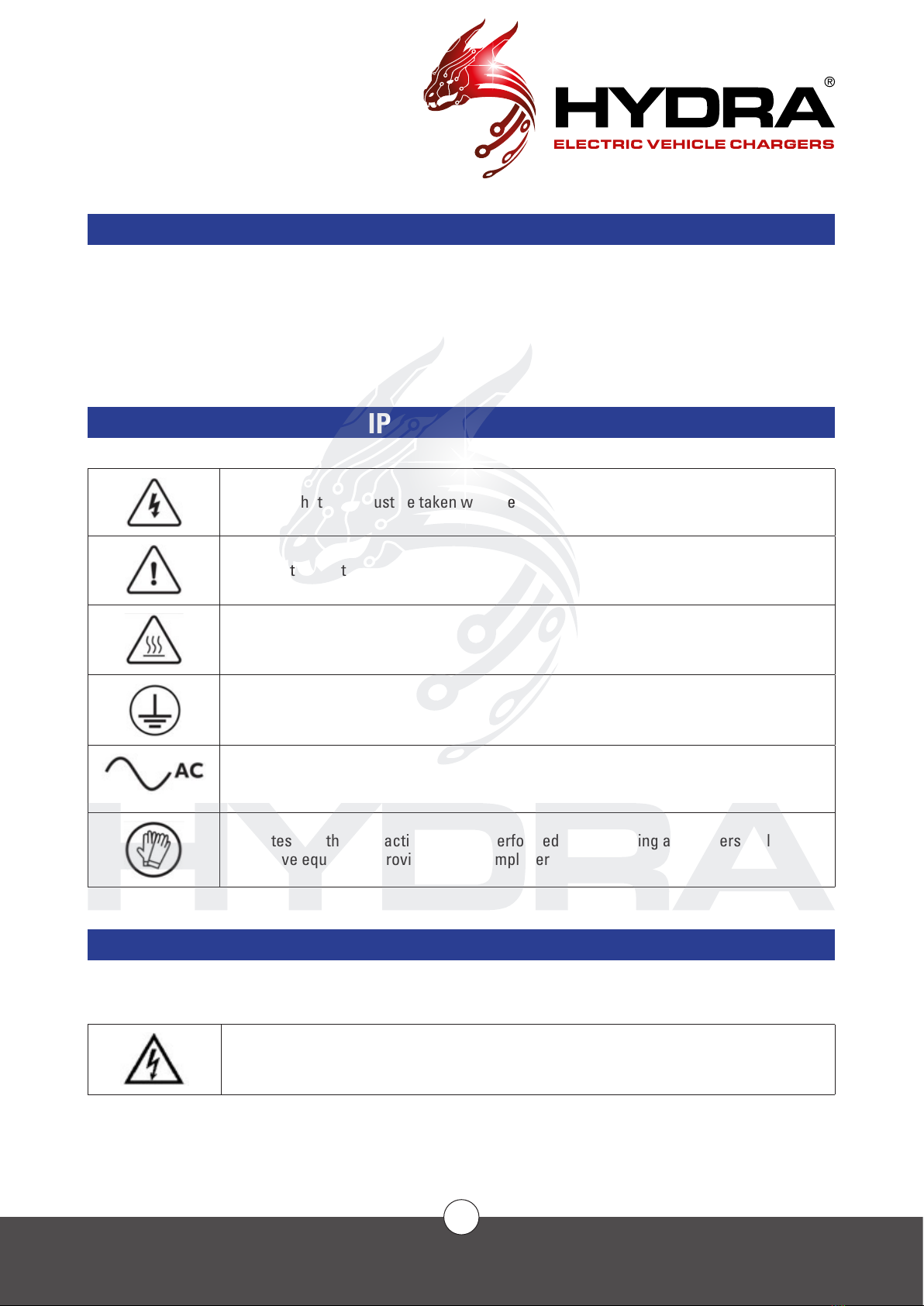
SAFETY ....................................................................................................................................................................................3
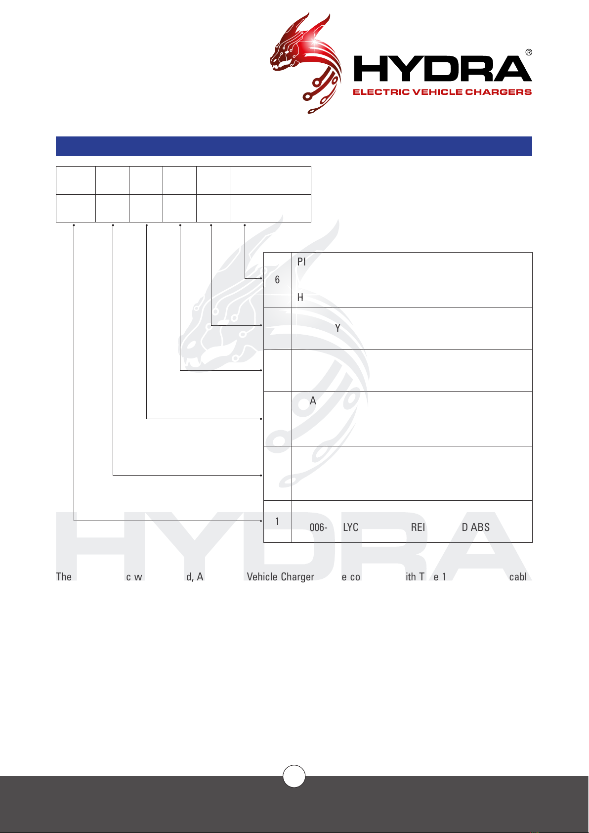
INTRODUCTION......................................................................................................................................................................6
Serial Number Identication..........................................................................................................................................6
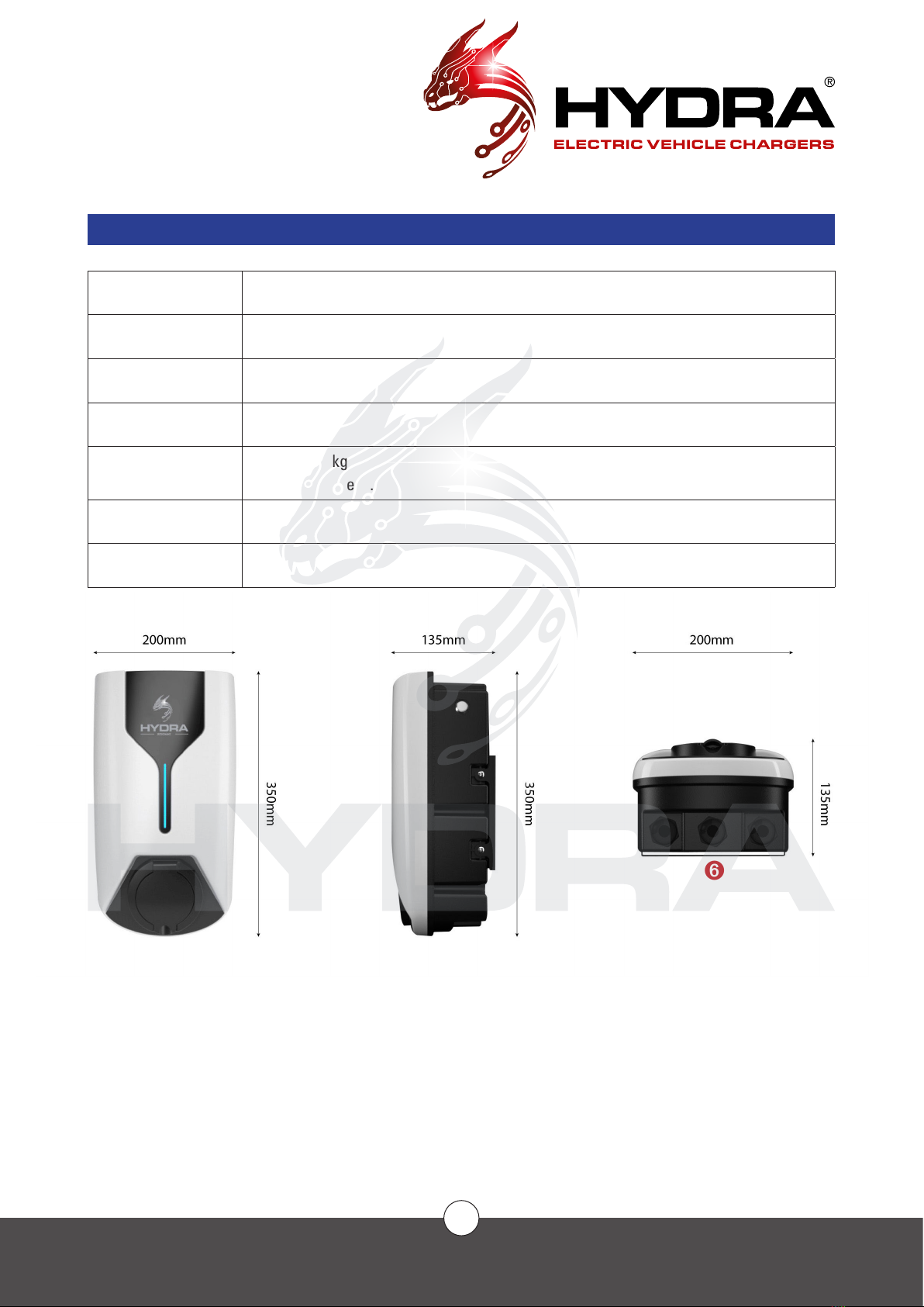
Appearance and Dimensions.........................................................................................................................................7
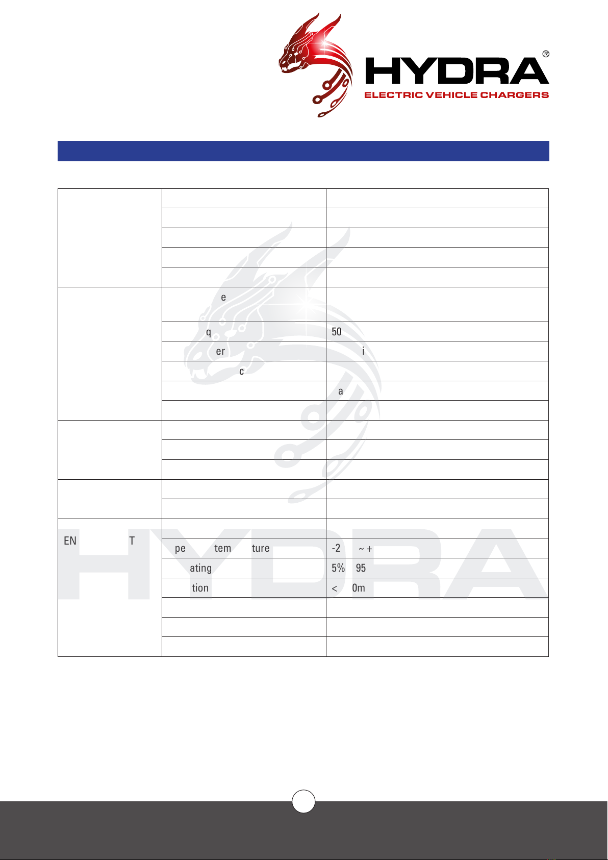
Technical Specications.................................................................................................................................................8
Product Features..............................................................................................................................................................9
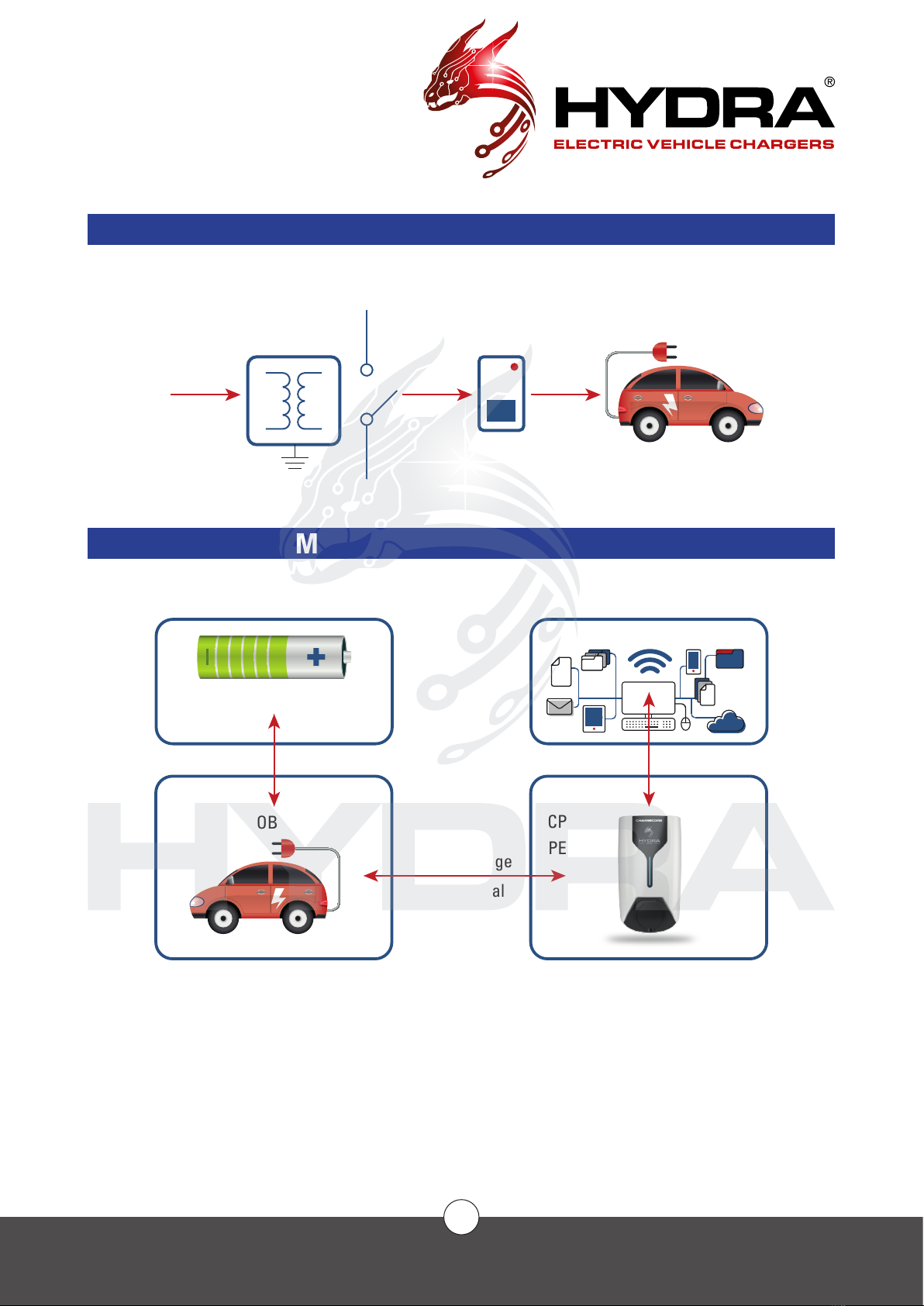
SYSTEM ARCHITECTURE ...................................................................................................................................................10
Electric.............................................................................................................................................................................10
Internal System Communications ...............................................................................................................................10
INSTALLATION .....................................................................................................................................................................11
Procedure........................................................................................................................................................................11
Site Space Requirements .............................................................................................................................................12
Mounting Requirements ...............................................................................................................................................13
Electrical Requirements................................................................................................................................................14
Network Connectivity Requirements..........................................................................................................................15
Tool Preparation .............................................................................................................................................................16
Installation Instructions - Using Quick-Connect Fly Lead.......................................................................................17
Connecting the Power Cable .......................................................................................................................................18
Installation Instructions - Without using Quick-Connect Fly Lead (please read important notice).................17
COMMISSIONING ...............................................................................................................................................................21
Power On Process .........................................................................................................................................................21
Charging Operation........................................................................................................................................................21
Emergency Operation....................................................................................................................................................21
Forced Unplugging and Recovery...............................................................................................................................21
Charging Operation........................................................................................................................................................22
Check before commissioning.......................................................................................................................................23
AFTER-SALES MAINTENANCE .........................................................................................................................................24
After Sales Service........................................................................................................................................................24
Disclaimer .......................................................................................................................................................................24
Maintenance...................................................................................................................................................................24
PROCEDURES .......................................................................................................................................................................26
APPENDIX.............................................................................................................................................................................27
LED indicator status identication ..............................................................................................................................27
Fault diagnostics (cause and resolution)...................................................................................................................27
Restriction of Hazardous Substances1 ......................................................................................................................28
Authentication ................................................................................................................................................................29

✆
01268 205 121
| www. hydraev.co.uk | sales@hydraev.co.uk
3
SAFETY
SAFETY ANNOUNCEMENTS
Before operating the EV charger, read the instructions and precautions carefully to reduce the risk of accidents.
The “caution, warning, hazard” notices in the product and product manual do not represent all safety concerns
to be observed and are only intended to supplement the various operational safety precautions.
In carrying out the company’s product and equipment operations, you must comply with relevant industry safety
norms and strictly abide by these instructions to provide the appropriate equipment precautions and special
safety instructions
IDENTIFICATION DESCRIPTION
Indicates that care must be taken with the operation or condition of hazardous voltage
Important security information must be followed very carefully
Indicates risk of burns from high-temperature areas or areas with high
component temperatures
Ground protected connection point
AC electricity
Indicates that the said action must be performed using clothing and/or personal
protective equipment provided by the employer
ELECTRICAL SAFETY
HIGH VOLTAGE
Some components of the power system operate with high voltage. Direct or indirect
contact with these components through non-insulated protective material poses a fatal
hazard.
The installation of AC power supply equipment must comply with safety regulations, and personnel carrying out
the installation of AC equipment must be qualied in high voltage AC-power operation.

✆
01268 205 121
| www. hydraev.co.uk | sales@hydraev.co.uk
4
SAFETY
It is strictly prohibited to wear watches, bracelets, rings or other conductive objects on your wrist or hand.
Turn off the power immediately if you nd water or moisture in the unit. When operating in humid conditions,
water should be strictly prevented from entering the equipment.
A “Do not operate” sign must be hung on switches and buttons that are not to be used during installation.
Construction of high-voltage lines can cause re or electric shock accidents.
The racking and wiring of AC cables through the area must comply with the local
regulations and specications. Only personnel qualied for high-voltage and AC
operations can carry out various high-voltage operations.
TOOLS
Special tools must be used for all high AC voltage operations.
THUNDERSTORMS
High AC voltage operations during thunderstorms are strictly prohibited.
Strong electromagnetic elds are produced in the atmosphere during thunderstorms. To avoid lightning
damage to equipment and personnel, do not carry out any operations during thunderstorms.
ELECTROSTATICS
Static electricity generated by the human body can damage electrostatic-sensitive
components on boards such as large-scale integrated circuits (ICs). To prevent static
damage to sensitive components, personnel must wear an anti-static bracelet when in
contact with equipment (hand-held boards, circuit boards, IC chips, etc.). The anti-
static bracelet must be well-grounded on the other end.
SHORT CIRCUITS
It is strictly prohibited to short-circuit the power supply system to the positive and
negative poles or to short the non-ground pole to ground during operation. Short
circuits can cause equipment to burn and pose a personal safety hazard.
In addition, the polarity of the cables and interface terminals must be strictly checked when carrying out live
work.
Power distribution operation space is limited. Before any operation, close attention must be paid to the choice
of operating space.
An insulation tool must be used during operation.
When working with electricity, care must be taken to keep your hands, wrists and arms steady, to prevent
accidents from a tool slipping, or from too much movement of a tool or your body.

✆
01268 205 121
| www. hydraev.co.uk | sales@hydraev.co.uk
5
SAFETY
SHARP CORNERS
When moving equipment by hand, wear protective gloves to prevent cuts.
POWER CABLE
Make sure that the cable label is correct before connecting the cable.
SIGNAL LINE
The signal cable should be tied separately from the power cable and at
least 15mm away.

✆
01268 205 121
| www. hydraev.co.uk | sales@hydraev.co.uk
6
INTRODUCTION
SERIAL NUMBER DESCRIPTION
AC006 T2 7 A01 PC ROU0120030002
1 2 3 4 5 6
6
PILE ID NUMBER
ROU01 2003 0002 - CUSTOMER ROMARIA 01
MADE IN MARCH 2020, PILE 0002
HERE FOUR DIGITS IN DECIMAL.
5 FOUNDRY
4 BOM VERSION
3
CHARGING POWER:
7: AC CHARGER RATED POWER 7KW
22: AC CHARGER RATED POWER 22KW
11: AC CHARGER RATED POWER 11KW
2
CHARGING STANDARD:
T2: TYPE2 AC CABLE VERSION
T2S: TYPE2 AC SOCKET VERSION
T1: TYPE1 AC CABLE VERSION
1PRODUCT NUMBER:
AC006- POLYCARBONATE REINFORCED ABS
The Hydra Zodiac wall-mounted, AC Electric Vehicle Charger can be congured with Type 1 J1772, Type 2 cable
(tethered) or socket (untethered 1 J1772, Type 2 cable (tethered) or socket (untethered). The system can be installed
outdoors (but for safety reasons, if the water/snow level reaches the charger connector it should not be used).

✆
01268 205 121
| www. hydraev.co.uk | sales@hydraev.co.uk
7
INTRODUCTION
APPEARANCE & DIMENSIONS
Use Residential, Commercial or Workplace Parking
Material POLYCARBONATE REINFORCED ABS
Installation type Wall-mounted
Cable layout Bottom
Weight Charger: 2.8kg
Charging Cable: 5.4kG
Cable length 5m
Charging socket Type1 or Type2
1 Status indicator light
2 Charging Lead Socket
3 Emergency Stop and Reset Button
4 Fixing Screws
5 Power Cable inlet
6 Ethernet port (option)
7 Cable Plug inlet
➊➊
➋➋
➌➌
➍➍
➎➎➏➏➐➐

✆
01268 205 121
| www. hydraev.co.uk | sales@hydraev.co.uk
8
INTRODUCTION
TECHNICAL SPECIFICATIONS
COMPONENT
SPECIFICATIONS
Dimensions 350(L) x 200(W) x 135(H) mm
Weight 3.5 kg (including cable)
Cable length 5 meters
Shell material Polycarbonate reinforced abs
Screen N/A
POWER
CHARACTERISTICS
Input voltage 230V AC (L/N/PE) ±10%
400V AC (L1/L2/L3/N/PE) ±10%
Input frequency 50Hz/60Hz
Rated power 7kW (single-phase) / 22kW (three-phase)
Measurement accuracy ≤±0.5%
Output voltage Same as input voltage
Output current 32A
DESIGN FEATURES UI Emergency stop button, LED indicator
Charging method Plug and charge, APP (timed start and stop)
Charging cable Type2 (Socket/Cable)
COMMUNICATION Web interface WiFi/Ethernet
OCPP OCPP 1.6j
WORKING
ENVIRONMENT
Usage Indoor/Outdoor
Operating temperature -20°C ~ +50°C
Operating humidity 5% ~ 95% no frost
Elevation <2000m
Protection level IP65
Cooling method Ambient air cooling
Ground detection 30mA AC, 6mA DC

✆
01268 205 121
| www. hydraev.co.uk | sales@hydraev.co.uk
9
INTRODUCTION
PRODUCT FEATURES
The HYDRA ZODIAC AC Charger has a modern design and user-friendly interface, designed for domestic and
workplace use.
SAFETY FEATURES
Hardware protection features:
Emergency stop protection
Overcurrent protection
Earth leakage protection
Comprehensive software protection features, providing multiple protections
IP65, EMC class B/C
SMART
The terminal charger is connected to the Open Charge Point Protocol platform online
Remote diagnostics, remote upgrades
Compatible with GB/T, Type1-SAEJ1772, Type 2 and IEC61851-1/2017
OCPP Smart charging
Support for OCPP1.6-J (later direct upgrade to 2.0)
CONVENIENT
Wireless or wired communication, exible networking
Open communication protocol for sweep charge, swipe charging and API services
Several settings to end the charge
Time limit
Amount of electricity
OPTIONAL FEATURES
Plug&Charge (optional)

✆
01268 205 121
| www. hydraev.co.uk | sales@hydraev.co.uk
10
SYSTEM
ARCHITECTURE
ELECTRIC
INTERNAL SYSTEM COMMUNICATIONS
BMS
OBC
PWM Charge
Pilot Signal
CP
PE
Internet OCPP1.6J+
OCPP cloud platform
CP
PE
ACTNS10kV
TN-C-S
10kV/400V
Transformer - Switch - Charger - Car

✆
01268 205 121
| www. hydraev.co.uk | sales@hydraev.co.uk
11
INSTALLATION
PROCEDURE
SAFETY INSTRUCTIONS
The operating voltage and current inside the charging system are high, and the following regulations should be
observed at all times to ensure personal safety:
1. Charging systems must only be installed by personnel who have been trained in, and have sufcient knowledge
of, the charging system. Always follow safety precautions and local safety regulations during installation.
2. To operate inside the charging system, make sure that the charging system is not live. The power input to the
charging system must be disconnected.
3. Distribution cable wiring should be reasonable and protective to avoid accidental contact when operating
power supplies.
VISUAL INSPECTION
Upon product delivery, check that the package is not damaged and that the label is complete and correct. If
there is an issue, immediately inform the carrier and take photos as evidence. At the same time, immediately
contact the manufacturer to discuss the issue.
Only after the goods arrive at the installation site can they be opened and the boxes opened for inspection.
Start by opening the box with the packing slip, taking out the packing list and checking it against each item.
Next, check the serial number of the box, the equipment packaging, the number and type of accessories and
the integrity of all items.
Following the packing list, check that accessories and accompanying documents are complete (refer to the
shipping list) and store the accessories and documents properly.
Carry out a visual inspection to ensure that the product is free of abnormal marks showing collisions, and of
scratches, cracks, dents, rust, breakage, or peeling of paint.
Sign receipt documents, make a record of the situation, keep documents and scan them for archives, or give
them to relevant parties.
ACCESSORY LIST
The packing list comes with the shipping documents.

✆
01268 205 121
| www. hydraev.co.uk | sales@hydraev.co.uk
12
INSTALLATION
SITE SPACE REQUIREMENTS
Adequate installation space should be reserved to ensure safe and reliable operation, ventilation and
maintenance of the equipment. Installation requires 250x400mm of space
149.6mm195.9mm
195.9mm

✆
01268 205 121
| www. hydraev.co.uk | sales@hydraev.co.uk
13
INSTALLATION
MOUNTING REQUIREMENTS
When the backplate is used to hang the charger on the wall, ensure that the wall smoothness error is within
±1.5mm per square meter and that the strength level of the installation position is not less than C30. Four M4
expansion screw holes are embedded in the mounting surface.
To avoid the back plate distorting when being screwed onto the wall, it is recommended that you x each screw
loosely one at a time and then tighten slowly once all screws are in place.
140mm 19mm
182.5mm
145mm
195mm
95mm
150mm
27.3
mm
100mm
Ø8mm
Ø8mm
Ø15mm

✆
01268 205 121
| www. hydraev.co.uk | sales@hydraev.co.uk
14
INSTALLATION
ELECTRICAL REQUIREMENTS
Cable type: TN-C-S/TN-S conrming the need for shielding as required by local laws or norms
If there is a shield, both ends of the shield are connected to the PE secure ground.
Cable diameter requirements are determined by the contractor or electrical engineer, based on power,
distance and industry standards, or the following recommendations:
ZR-YJV-multi-core-sheath power cable.
The voltage level is 450/750V or higher.
A temperature of at least 90°C should be achieved.
PE Safety ground wire requires the same size model as the N wire, or uses the following recommended
requirements:
When the phase line is greater than 35 mm2, the ground line should be no less than half of the phase
line section.
When the phase line is greater than 16 mm2 and less than or equal to 35mm2, the ground line should
be consistent with the phase section.
The section of the ground line must not be less than 16 mm2.
The recommended power distribution input wire diameter of the charger should not be less than the following
recommended values and should have a separate circuit breaker and leakage (the following table is at 25°C
environment, YJV22 (armoured) cable in the soil directly applying ow as a reference, according to the
actual cable material and laying method to determine the specic wire diameter).
Charger power(kW) 7 11 22
Input voltage 240V 240V (L-L) 400V
Input current 32A 16A 32A
Recommended line
diameter 6mm26mm26mm2

✆
01268 205 121
| www. hydraev.co.uk | sales@hydraev.co.uk
15
INSTALLATION
NETWORK CONNECTIVITY REQUIREMENTS
The recommended way to connect to the network is to access the Wi-Fi module integrated in the charger.
Make sure the local signal strength is strong and stable; otherwise a signal amplier must be installed.
If your chosen method of internet connection is via WIFI please check the signal strength in your desired place
of installation. If there is no or extremely poor connection a standard wired internet connection (ethernet) is
available. Wired connections must meet the following requirements:
RJ45 Ethernet
Network cable type: 5e class or greater, 8P plus PE, shielding wire.
It is recommended that the line length is less than 75m. Greater than 75m length requires a customised
engineering solution.
Minimum bandwidth required:
Upstream: 128 kbps
Downstream: 4 Mbps
Demand connection reliability: 99.9%.
For special congurations, please contact us.

✆
01268 205 121
| www. hydraev.co.uk | sales@hydraev.co.uk
16
INSTALLATION
NAME DESCRIPTION QTY
Multimeter Checking the electrical connections and electrical parameters 1
Electric impact drill Drilling 1
Impact drill bit (Ø6mm) Drilling 2
Tape measure (5m) Measurement 1
Level Measurement 1
Crosshead screwdriver Unpacking 1
Pliers Unpacking 1
Wire Stripper Removing the insulation sheath / jacket 1
Terminal pressure line pliers Pressing the terminals 1
Bevel cutting pliers Cutting the cable 1
PVC tape and sheath Insulation tape and insulation cladding connection 1
Personal protection tools Ensuring the health and safety of operators 1
TOOL PREPARATION
STANDARD TOOLS

✆
01268 205 121
| www. hydraev.co.uk | sales@hydraev.co.uk
17
INSTALLATION
INSTALLATION INSTRUCTIONS - USING QUICK-CONNECT FLY LEAD
PLEASE NOTE: THE ZODIAC EV CHARGER HAS BEEN DESIGNED TO BE CONNECTED TO THE AC ELECTRICAL
SUPPLY USING THE QUICK-CONNECT FLY LEAD. THIS SIMPLIFIES THE INSTALLATION PROCESS AND ENSURES
THE ELECTRONIC COMPONENTS WITHIN THE EV CHARGER HOUSING ARE NOT DISTURBED. IT ALSO ALLOWS
THE ZODIAC TO BE WALL OR PEDESTAL MOUNTED BEFORE IT IS CONNECTED TO THE AC SUPPLY.
IF YOU CHOOSE NOT TO USE THE QUICK-CONNECT FLY LEAD AND OPEN THE ZODIAC CHARGER HOUSING TO
WIRE IT DIRECTLY THIS IS DONE AT YOUR OWN RISK. PLEASE SEE PAGE 19 FOR DETAILS OF HOW TO OPEN
THE HOUSING AND WHICH COMPONENTS NEED TO BE TREATED WITH EXTREME CARE.
TRANSFER LOADING AND UNLOADING
Do not drop or hit the device.
INSTALLATION
Secure the base to the wall.
NB: To avoid the back plate distorting when being screwed onto the wall, it is recommended that you x
each screw loosely one at a time and then tighten slowly once all screws are in place.
Carefully and slowly lower the charger into place.
Make sure that the cable has been passed into the cabinet along the seal sleeve.
Ensure that the cabinet holes and bolts are aligned.
Lock the nuts to 95.5 Nm.
Keep the device upright – do not tilt more than ±15°
Mount the charging pile on the hanger and lock the charging pile
Wall xing bolts
(using suitable rawlplugs
where appropriate)
Mounting
screws
Mounting backplate Hydra Zodiac
EV Charger
Mounting
backplate

✆
01268 205 121
| www. hydraev.co.uk | sales@hydraev.co.uk
18
INSTALLATION
CONNECT THE POWER CABLE
Note: Turn off switches and pull out all fuses before connecting electrically
CONNECT THE GROUND CABLE
The charging system uses a common grounding method, using a ground cable to connect the ground copper
row of the charging cabinet with the main ground row.
CONNECT THE AC INPUT
1 The AC input cable is routed from the user’s power distribution switch and is connected to the output
terminal of the user switch when power is ready to be turned on. The user distribution switch should
have overcurrent, short circuit, lightning strike and other protective devices. The capacity of the power
distribution switch is recommended as not less than 1.5 times the actual load capacity.
Please ensure the The Zodiac has its own dedicated circuit – EV charging equipment in the UK is required
by law to have its own dedicated circuit’
2 The L1-phase, L2-phase, L3-phase and N-zero cables of the AC input cable should use brown, black, grey
and blue cables (standard reference below). If the cable has only one colour, the line number identication
is pasted or marked with different colour insulation at both ends of the cable.
3 Cables should not have severed heads, broken heads or scratches.
Colour Brown Blue Yellow and Green
Phase order L N PE
PHASE LINE / ZERO STUD / IDENTIFICATION CHART
P
N
L
PE
N
L
NOTE: We recommend wiring the Zodiac to the mains supply using the easy-connect module (shown above).
However if the customer wishes to remove this component it is possible to hardwire the power supply cable
directly into the Zodiac. When you unscrew and open the body of the Zodiac charger please handle the faceplate
with great care. It does not completely separate from the unit and certain wires inside must remain connected
between the faceplate and body of the Zodiac. Other internal components are delicate and instrumental to
maintaining safety measures therefore it is extremely important these parts are not disturbed or touched during
installation.

✆
01268 205 121
| www. hydraev.co.uk | sales@hydraev.co.uk
19
INSTALLATION
INSTALLATION INSTRUCTIONS
WITHOUT USING QUICK-CONNECT FLY LEAD
PLEASE NOTE: THE ZODIAC EV CHARGER HAS
BEEN DESIGNED TO BE CONNECTED TO THE AC
ELECTRICAL SUPPLY USING THE QUICK-CONNECT
FLY LEAD. IF YOU CHOOSE NOT TO USE THE QUICK-
CONNECT FLY LEAD AND OPEN THE ZODIAC
CHARGER HOUSING TO WIRE IT DIRECTLY THIS IS
DONE AT YOUR OWN RISK.
THE FOLLOWING PAGES ARE NOT TO BE VIEWED
AS INSTRUCTIONS BUT SIMPLY A WARNING.
OPENING THE ZODIAC EV CHARGER HOUSING
The faceplate of the Zodiac EV charger is held in
place with 6 small screws (three each side). These
cannot be accessed once the EV charger has been
mounted onto the wall.
Lay the Zodiac face down on a level surface taking
great care not to scratch the faceplate. Use the foam
sheets from the original packaging to protect it.
In addition to the power cables to the socket
(Untethered version) there is a communications
antenna wire and power cable to the LED indicator
attached to the back of the faceplate.
It is vitally important to the function of the EV
charger that these wires are undisturbed.

✆
01268 205 121
| www. hydraev.co.uk | sales@hydraev.co.uk
20
CONTENTS
FaceplateLED status indicator
power cable
Power-in
Communications
Antenna
CT clamp
Charge Socket
INSIDE THE ZODIAC EV CHARGER (UNTETHERED MODEL)
ACCESS PORTS UNDER THE ZODIAC CHARGER
The Zodiac has three access ports underneath, these are for Power in (LEFT on all models), RJ45 Ethernet
cable (CENTRE on some models), Charging Cable Out (RIGHT on tethered models only)
Other manuals for ZODIAC
1
Table of contents
Other Hydra Batteries Charger manuals
Popular Batteries Charger manuals by other brands

Motomaster
Motomaster ELIMINATOR WORKSHOP 011-1980-4 instruction manual

Green motion
Green motion RANGEXT 160 Technical documentation

Motorola solutions
Motorola solutions PMLN6621 user guide

AquaAmp
AquaAmp REC10 installation instructions

AddEnergie
AddEnergie CoRe+ C+V1-PED-ADD installation guide

VTOMAN
VTOMAN Jump 600X user manual