Hydrafeed MSV 80 User manual

Short Magazine Barfeed
MSV 80
Operation Manual
2017-12-V12.0-SDH
Hydrafeed Ltd.
Talgarth House, Bond Avenue
Mount Farm, Milton Keynes
MK1 1JD
Tel : 01908 376331 Email: [email protected]
Fax: 01908 647843 www.hydrafeed.co.uk

Contents
1. Mechanism......................................................................................................................................1
1.1 Notes for Your Safety ...........................................................................................................1
1.2 Description ............................................................................................................................1
1.3 Identification..........................................................................................................................1
1.4 Transport and Unpacking.....................................................................................................2
1.5 Accessories Supplied...........................................................................................................2
1.6 Preparations for installing the barfeeder............................................................................2
1.7 Mounting, Anchoring and Alignment ..................................................................................3
1.8 Changing the Pushrod Position...........................................................................................4
1.9 Retraction of the Barfeeder for Spindle Service.................................................................4
1.10 Material Rack Height and Diameter Adjustment...............................................................4
1.11 Maintenance ........................................................................................................................4
Figure 1 – Floor Plan ...........................................................................................................5
Figure 2 – Assembly Plan....................................................................................................6
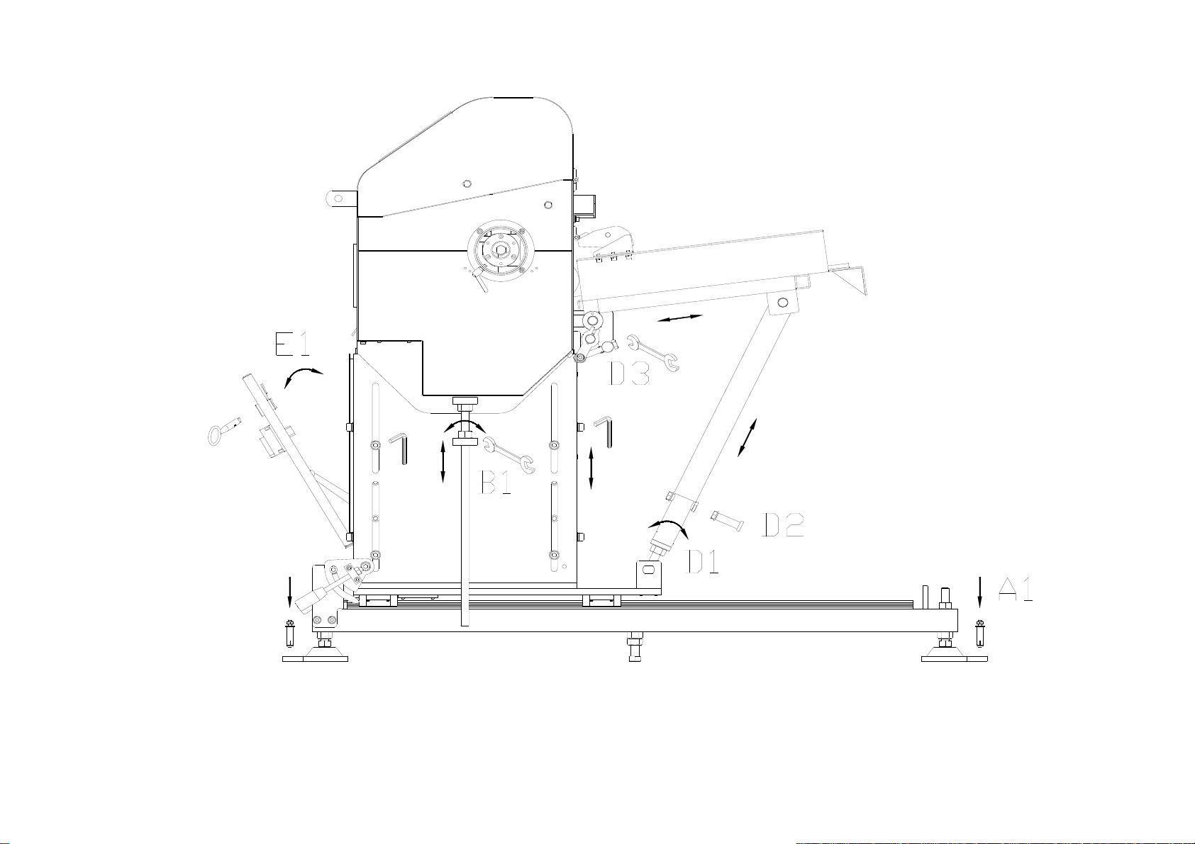
Figure 3 – Manual Adjustments..........................................................................................7
Figure 4 – Changing Pushrod Piston.................................................................................8
Figure 5 - Retracting The Barfeeder..................................................................................9
Figure 6 - Transportation by forklift truck........................................................................10
Figure 7 - Transportation by crane/hoist cables.............................................................11
Figure 8 – Greasing the Ball screw ..................................................................................12
2. Operation Panel............................................................................................................................13
2.1 Power On and First Screen ................................................................................................13
2.2 Select Manual / Auto mode.................................................................................................14
2.3 Manual operation ................................................................................................................15
2.4 Auto cycle............................................................................................................................16
3. User Setup ....................................................................................................................................22
3.1 User Setup Introduction .....................................................................................................22
3.2 BAR TYPE / Diameter..........................................................................................................24
3.2.1 Bar Type.....................................................................................................................24
3.2.2 Bar diameter Setting.................................................................................................25
3.2.3 Material Selection .....................................................................................................25
3.2.4 Push torque Adjustment ..........................................................................................26
3.3 Component Length .............................................................................................................27
3.4 Position Setup.....................................................................................................................28
3.4.1 End of Bar Position..................................................................................................28
3.4.1.1 Spindle length Setup......................................................................................29
3.4.1.2 Clamping length Setup...................................................................................29
3.4.2 Loading selection .....................................................................................................30
3.4.3 Pushrod retract Position.........................................................................................32
3.5 Feeding type........................................................................................................................34
3.5.1 Sub spindle Pull.................................................................................................35
3.5.2 Barfeeding with / without Turret......................................................................38
3.6 Back Stop ............................................................................................................................50
3.7. Shaft Load...........................................................................................................................54
3.8 Chucking mode...................................................................................................................56
3.9 Center line correction.........................................................................................................57
3.10 Barfeed Programs.............................................................................................................58
3.10.1 Ways To search DATA Address ............................................................................58
3.10.2. To Save MMI Data to DATA 01 ..............................................................................60
3.10.3. To Transfer DATA 10 to MMI Data Base...............................................................64
3.10.4. To Reset DATA 10..................................................................................................66
3.11 Other ..................................................................................................................................68
3.11.2 Eject remnant.......................................................................................................68

3
3.11.3 Part Counter ............................................................................................................72
3.11.4 Bar length (MAX setting)........................................................................................74
3.11.5 Hexagonal bar Time setting ...................................................................................75
3.11.6 1st Feed error correction.......................................................................................76
3.11.7 Chuck close bar check Torque value setting .......................................................77
4. System Setup ...............................................................................................................................78
4.1 System Setup Introduction.................................................................................................79
4.2 Interface Signals Selection.................................................................................................80
4.2.1 Bar End signal function............................................................................................80
4.2.2 CNC Auto Mode signal function ..............................................................................82
4.2.3 CNC Emergency Stop signal function.....................................................................83
4.2.4 Interface signal Optional function selection...........................................................83
4.2.5 CNC Chuck open / M code signal selection............................................................85
4.3 Carriage position setup......................................................................................................88
4.4 Loading position setup.......................................................................................................90
4.5 Lathe selection....................................................................................................................91
4.6 Chuck open/close Bar check function setup....................................................................91
4.7 Time delay for chuck close then Pushrod retract setup..................................................93
4.8 Bar end then Turret comes to new bar loading position function setup.......................93
4.9 Cover/Sliding rail operation function setup....................................................................100
4.10 Servo motor speed value setting...................................................................................100
4.11 Demo function.................................................................................................................110
4.12 Sensor position setting ..................................................................................................110
4.13 Chuck type Selection......................................................................................................114
4.14 Shaft Load space setting................................................................................................115
4.15 Maintenance ....................................................................................................................116
4.16 Pulse Output Selection...................................................................................................117
4.17 Back Stop option.............................................................................................................118
4.18 Thickness of shaft load plate.........................................................................................119
4.19 Eject remnant by new option .........................................................................................120
5. History.........................................................................................................................................121
5.1 Alarm History.....................................................................................................................121
5.2 Workpiece record..............................................................................................................122
6. PLC Input / Output Signal and data list....................................................................................123
7. Alarm List....................................................................................................................................124
8. Warning List ...............................................................................................................................137
9. Appendix : Electronic Controller ..............................................................................................148
9.1 Input List............................................................................................................................148
9.2 output List..........................................................................................................................149
9.3 Spare Parts List.................................................................................................................150
9.4 Electrical components distribution.................................................................................154
9.5 Electric Circuit Diagram ...................................................................................................155
10. Parameter List ..........................................................................................................................169
10.1 User parameter list..........................................................................................................169
10.2 System Parameter List ...................................................................................................171
11. Appendix : Mechanism............................................................................................................173

1
1. Mechanism
1. Mechanism
1.1 Notes for Your Safety
Before operating the machine, be sure to read the operating instructions carefully.
Your barfeeder is designed and built for maximum ease and safe operation.
Read the appropriate instructions or manuals before attempting operation or maintenance of the
equipment. Make sure, you understand all instructions.
Do not operate the barfeeder, unless the protective cover is closed.
Strictly follow the instructions and warning signs on the machine.
Do not operate equipment, unless proper maintenance has been regularly performed and
equipment is known to be in good working condition.
Do not operate equipment, if unusual or excessive heat, noise, smoke, or vibration occurs.
Report any excessive or unusual vibration, sounds, smoke, or heat as well as any damaged
parts.
Make sure that equipment is properly grounded. Consult National Electric Code and all local
codes.
Disconnect main electrical power, before attempting mechanical repair or maintenance.
Don’t reach any control or power enclosure area, unless electrical power is off.
Do not allow the operation or repair of equipment, by untrained personnel.
Replace blown fuses of the same size and type as originally furnished.
Remove any loose parts or tools left on machine or in the work area, before operating the
machine.
Before pressing the cycle start button, be sure that proper functions are programmed and that all
controls are set in the desired modes.
Do not exceed the rated capacity of machine.
Use feed tube liners in the spindle of the lathe when using barfeeder.
If bar stock will not feed properly, carefully diagnose the problem to determine the best
corrective measures.
1.2 Description
MSV80 is an advanced design electronic barfeeder for all high speed automatic or CNC
controlled lathes, machining high precision pieces from round to different section bars.
MSV80 consists of a servo driven timing belt system, which feeds the bar to the spindle within
the noted tolerance without any stopper on the turret or up to a stopper depending on the
tolerance requirements, a magazine rack on which bars are stocked and loaded on a channel
through an automatic mechanism in order to feed in to spindle by belt drive system, and
electronic control panel, which allows the operator to set parameters to control the operation.
1.3 Identification
The serial number of each barfeeder is given on an identification plate located on the machine.
State the serial number in all correspondence concerning the barfeeder.

2
1. Mechanism
1.4 Transport and Unpacking
MSV80 barfeeder is delivered in a wooden crate. The net weight around 510 kg, gross weight
around 700kg. - WARNING -
To avoid any damage during unpacking, follow these recommendations carefully.
1.4.1 : Unpacking
.Bring the crates containing the barfeeder near to the machine tool.
. Remove the cover and the sides of the crate.
. Unscrew the anchoring bolts and take the feet of the case.
1.4.2 : Transportation by forklift truck
<Caution>
WHEN MOVING BY FORKLIFT , BEWARD
THE screw UNDERNEATH THE BAR FEEDER!
See Figure 6 ‘Transportation by forklift truck’ A and B
1.4.3 Transportation by crane/hoist cables
<Caution>
WHEN USING THE HOIST CABLES AND LIFTING THE BAR FEEDER MAKE SURE
THE CABLES HANGING IN THE CORRECT POSITION AND THAT YOU DO NOT DAMAGE THE CASING
OR ATTACHED PIECES!
See Figure 7 ‘Transportation by crane/hoist cables’
1.5 Accessories Supplied
The various accessories required for the operation and maintenance of the MSV80, are
supplied with each barfeeder. These accessories are packed in the crate :
(a) Electrical connection cabinet key
(b) Additional Pushrod.
(c) Interface Connection Cable
1.6 Preparations for installing the barfeeder
To ensure a correct installation and a rapid start up:
1.6.1 The assembly and start-up must be carried out by the technicians or representatives of
Hydrafeed.
1.6.2 In the customer’s interest, the maintenance and operating staff should be present at the
installation of the barfeeder for appropriate training on its use thereafter.
1.6.3 The Lathe
It must be completely installed, with its cylinder and chucking system.
It must be ready for production.
For the day of installation, it must be totally available.
The interface must be completed and ready for the following electrical connections.
Power Supply, 1x220V, 50/60Hz or 1x400V,50Hz(Optional)
Emergency Stop
Safety Lines
‘End of Bar’ Signal
Feed Bar Command

3
1. Mechanism
1.6.4 The Reducing Liners for the Lathe
The customer must ensure that the headstock reducing liners requires for the lathe are
available for the bar types and sizes to be machined during the first month of the production.
These liners can be obtained from the lathe supplier or made by the customer.
1.6.5 Ground Space Requirements
The customer must ensure that there is enough space for the installation of the bar feeder on
the axis of the machine tool of the rear of the spindle. See floor plan. See Figure 1 ‘Floor
Plan’, Figure 2 ‘Assembly Plan’
1.6.6 Barfeeder Foundation
The foundation for the barfeeder must be a high quality concrete with sufficient thickness for
correct anchoring of the legs. The legs will be fastened to the slab by expansion bolts.
1.6.7 Lathe Foundation
The lathe should be installed on the same foundation as the barfeeder. A perfect alignment of
the barfeeder relative to the head of the lathe is a prerequisite condition to obtain high
precision machining.
As soon as the barfeeder and the lathe have been aligned, any shift is unacceptable.
Accelerations, decelerations and/or vibrations may shift the lathe. To avoid the risk of the
machine shifting, we recommend to secure positioning blocks to the foundation at the corners
of the lathe.
1.7 Mounting, Anchoring and Alignment
<Caution>
The alignment of the barfeeder relative to the machine tool is the most important operation of the
installation and must be carried out with extreme care. The amount of time taken for the
alignment procedure is unimportant when compared with the problems which may be occurred
on the machine or barfeeder.
1.7.1 Preparation for the Alignment
Pull the nylon rope through the headstock of the lathe, the front and the rear
pushrod support -use the hole on the piston back support part-.and tighten.
1.7.2 Rough Alignment
Place an arrow shaped sheet metal piece with a magnet to the rear
headstock face of the lathe and into the hole on the front pushrod support,
in order to obtain two checking points around the nylon rope.
Loose the side bolts and adjust the height by adjusting height adjustment screws on the left
and the right of the barfeeder. See Figure 3 ‘Manual Adjustments’ B1.
When lateral adjustment and the height is adjusted bolt the barfeeder to the ground.
See Figure 3 ‘Manual Adjustments’ A1
1.7.3 Accurate Alignment
The nylon rope must be tight-stretched to avoid bending by its own weight
After all these operations, repeat the steps defined at point 1.7.2.
The alignment limits measured at the inlet of the headstock and in the centring lunette should
be +/- 0.2 mm maximum, in both horizontal and vertical direction.
After completing all operations tighten all the nuts and the bolts

4
1. Mechanism
1.7.4 Connection to Floor
Control the firmness of the floor. It must be made up of high quality concrete. This allow correct
anchorage by means of fixing bolts supplied with the barfeeder. See Figure 3 ‘Manual
Adjustments’ A1
1.8 Changing the Pushrod Position
In order to take the pushrod piston out, follow the steps shown on the Figure 4 ‘Changing
Pushrod Piston’. By manual operation, take the mechanism up Step 1. Pull the piston to the
right and take out the back pin from its retaining hole Step 2. Turn the piston upside down Step
3. Pull the piston to the left to take out. Step 4.
1.9 Retraction of the Barfeeder for Spindle Service
If the retraction of the barfeeder is needed for any spindle service, unlock the locking system by
sliding the locking pin through its slot, as shown on the Figure 5 “Retracting The Barfeeder” F1.
Unlock the locking device, now it is possible for barfeeder to slide back Figure 5 F2.
1.10 Material Rack Height and Diameter Adjustment
Depending on the shape and diameter of the bar to be used, the height and the angle of
material rack may be adjusted. The height may be adjusted roughly by changing the pin
position, see Figure 3 ‘Manual Adjustments’ D2, or fine by turning the lower support tube.
See Figure 3 D1.
For the diameter changes, by adjustment screw, the material rack may be slide with respect to
the loading mechanism, so that different diameters can be handled by the barfeeder.
See Figure 3 D3.
1.11 Maintenance
Grease the ball screw monthly.
See Figure 8 Greasing the Ball screw

5
~
pusher maximum extension length :
~
~
Figure 1 – Floor Plan

6
Figure 2 – Assembly Plan

7
Figure 3 – Manual Adjustments

8
Figure 4 – Changing Pushrod Piston

9
Figure 5 - Retracting The Barfeeder

10
Figure 6 - Transportation by forklift truck

11
Figure 7 - Transportation by crane/hoist cables

12
Figure 8 – Greasing the Ball screw

13
2. Operation Panel
2. Operation Panel
2.1 Power On and First Screen
Main switch ON
Touch on home symbol and see main menu
MAIN SWITCH
1
NEXT SCREEN

14
2. Operation Panel
2.2 Select Manual / Auto mode
Select manual mode and see that is impossible to
use auto mode.
Possible to enter parameters, alarm history and
plc I/O screen.
Don’t select manual mode and don’t enter
parameters screen if CNC and bar feeder are
running in auto mode, it can be dangerous.
Select auto mode and see that is impossible to use
manual mode.
Possible to enter parameters, alarm history and plc
I/O screen.

15
2. Operation Panel
2.3 Manual operation
- Touch on symbol and jump to manual - Touch on up button.
screen. - Loading mechanism moves up until centring
active bar diameter.
- Touch on down button. - Touch on forward button.
- Loading mechanism moves down until down limit. - If the loading mechanism is up flag moves,
although pushrod moves until forward limit.

16
2. Operation Panel
- Touch on back button. - Touch on home picture.
- If the loading mechanism is up flag moves, - Jump to main screen.
although pushrod moves until back limit.
Note:
If you want to move loading mechanism up or down, pushrod and flag must be at reference position.
And you also want to move pushrod or flag, loading mechanism must be at up position or down
position. And you can see all motions on the screen.
2.4 Auto cycle
-Bar feeder is running in auto mode.
-See the number of cut down pieces at bottom right.
-See the number of pieces that will be cut down
at centre.
-You can see all the motions on the screen.
-Touch on symbol and jump to auto
screen.

17
2. Operation Panel
Table of contents
Other Hydrafeed Industrial Equipment manuals
Popular Industrial Equipment manuals by other brands

Schulte
Schulte SMR-800 Operator's manual

AAF
AAF AmericanAirFilter K Installation, operation and maintenance instructions

SMC Networks
SMC Networks CJP Series Operation manual

Siemens
Siemens 8MF1 Series operating instructions

Raven
Raven DCS 700 Installation and service manual

probst
probst TAK Series operating instructions