SETTING UP YOUR SYSTEM
1.IMPORTANT! Before attaching the regulator to the CO2tank,
slowly open the tank valve wide for 3-5 seconds to blow out any
sediment. Close the valve tightly.
Whenever you are opening the tank valve, do it extremely
slowly to avoid damaging the inner seals in the regulator.
2. Make sure the washer is seated evenly in the regulator valve.
Insert one of the provided white plastic washers inside the large
brass nut. This will help prevent leaks. Replace the white plastic
washer with each tank change. This will ensure a tight fit, without
leaks, each time. Rubber replacement washers can be purchased
at your local indoor gardening store (item CORING).
3. Securely attach regulator assembly to tank. Use a crescent
wrench to make this connection. Do not use pipe thread tape or
lubricants when making the connection to the tank. Do not use
pliers or channel-locks to tighten the nut. Do not overtighten the
nut. DO NOT OPEN THE TANK VALVE YET.
NOTE: When attaching the regulator to the tank, do not hold on to
the clear plastic meter. Putting pressure on the clear plastic meter
will break the seal at the base and permanently damage the unit.
This will not be covered under the warranty.
4. Insert the shorter extension tube into the plastic fitting on the
back of the flow meter.
5. Insert the other end of the extension tube and insert it onto the
“T” fitting.
6. Do not touch the solenoid during or for at least 5 minutes after
operation, as it can reach temperatures of 80°C/176°F.
ATTACHING THE DISTRIBUTION RING
The distribution ring is designed to be suspended above the plants
in a circular pattern.
1. Screw in the eyelets according to the diagram.
2. Thread the tubing through the eyelets in a circular pattern over
your growing area.
3. Connect the return end to the other side of the “T” fitting.
CO2
is heavier than air and will spread downward from the distribution
points. Make sure the distribution tubing is secured and does not
interfere with your lighting or light movement systems.
NOTE: If you opt not to use the distribution ring, connect a 1/4" tube
to the regulator and run the tube into the grow room, then zip tie the
tube to the back of a wall mount fan to disburse the CO2. We also
recommend using the 12" Pivot Fan (item ACFV12HD) to blow air back
up towards the ceiling. This will help keep the CO2in circulation.
ADJUSTING THE REGULATOR
1. Before opening the valve on the CO
2
tank, slightly open (1/2 turn
counter-clockwise) the black flow rate adjustment knob on the
regulator to relieve the pressure from the gas being released.
Failure to do this can permanently damage the unit and void the
warranty.
2. Open the valve on your CO
2
tank 2 or 3 rotations. Check for CO
2
leaks at all connections by using soapy water.
3. To set the flow rate, turn the black flow rate adjustment knob.
The ball will move up and down inside the meter tube. Adjust the
knob to your desired flow rate. WARNING: Opening the black
dial completely, where the ball moves past the top of the flow
scale, can allow the CO
2
to flow too fast. This can cause freezing
of the regulator and will void the warranty.
If the psi (pounds per square inch) gauge doesn't read between 20
and 30 psi when the regulator is securely attached and set up, and
the tank is full, adjustment will be necessary. Remove the green
"CO2" sticker on the front of the unit (if applicable). Adjust the bolt
found under the sticker until the gauge reads between 20 and 30
psi. You will need a 4mm (5/32") hex key or a flat head screwdriver,
depending on which model you have.
Congratulations on your purchase of our carbon dioxide (CO2) system. Its unique
design and top quality components make it the best CO2enrichment system
available to the home gardener. Check all your parts carefully against the diagram
and components listed below.
PLEASE READ ALL DIRECTIONS CAREFULLY BEFORE SETTING
UP YOUR SYSTEM
COSYS
COSYS20
Congratulations on the purchase of our carbon dioxide (CO2) system.
Its unique design and top quality components make it the best CO2
enrichment system available to the home gardener. Check all your parts
carefully against the diagram and components listed below.
PLEASE READ ALL DIRECTIONS CAREFULLY
BEFORE SETTING UP YOUR SYSTEM.
Our CO2systems are guaranteed to the original owner for 3 years from the date of purchase. Misuse, abuse, or failure to follow
instructions are not covered. If you have a problem, recheck your system and timer to isolate the problem. If this doesn’t rem-
edy the situation, call the place of purchase to get a Return Authorization for the faulty part. Send only that part. Unauthorized
returns will not be accepted. Save your receipt/invoice — a copy is required for all warranty work.
THE HYDROFARM GUARANTEE
CO2Instructions
SETTING UP YOUR SYSTEM
1. IMPORTANT! Before attaching the regulator to the
CO2 tank, slowly open the tank valve wide open for 3-5
seconds to blow out any sediment that may be in the tank
valve. Reclose the valve tightly. Whenever you are open-
ing the tank valve, do it extremely slowly to avoid damag-
ing the inner seals in the regulator.
2. Make sure the washer is seated evenly in the regulator
valve. Then attach regulator assembly to tank.
DO NOT OPEN THE TANK VALVE YET.
3. Insert the shorter extension tube into the plastic fitting on
the back of the flowmeter.
4. Take the other end of the extension tube and insert it onto
the “T” fitting as shown.
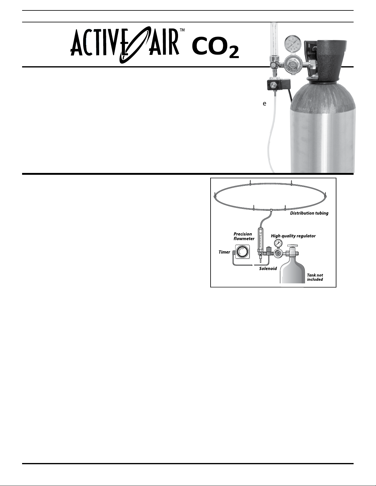
DISTRIBUTION RING
The distribution ring is designed to be suspended above the
plants in a circular pattern.
1. First screw the eyelets in according to the diagram.
2. Then thread the tubing through them in a circular pattern
over your growing area.
3. Connect the return end to the other side of the “T” fitting.
CO2 is heavier than air and will spread downward from the distri-
bution points. Make sure the distribution tubing is secured and
does not interfere with your lighting or light movement systems.
ADJUSTING THE REGULATOR
Once the system is securely attached and set up, your regulator
can be adjusted.
1. Plug your solenoid cord into the timer and rotate the dial
until the tabs are in an “ON” position.
2. Very, very slowly open the tank valve until it is fully open.
3. Now, using a screwdriver and a crescent wrench adjust the
PSI gauge so it reads 30 PSI.
4. Tighten the locknut.
5. Unplug the solenoid valve.
* NOTE: THIS UNIT IS NOT DESIGNED TO BE USED WITH ELECTRONIC CONTROLLERS. THE
CONSTANT SWITCHING ON & OFF OF THE CO2WILL CAUSE COMPONENTS TO FREEZE. THIS
COULD EMPTY THE TANK OR INHIBIT CO2 DELIVERY.
INSTRUCTION MANUAL
COSYS/COSYS20
COSYS/COSYS20