HydroMassage HM200 Manual

DELIVERY, UNPACKING
AND SETUP
INSTRUCTIONS
PH 727-536-5566 Ext 1014
Fax 727-536-6633
salessupportteam@hydromassage.com
15395 Roosevelt Blvd.
Clearwater FL. 33760
www.hydromassage .com
Class I, Type B, IPXO, Equipment
Revised Jan 15, 2021
Water Requirements: 12 gallons of DISTILLED water.
Specications
Model HM200
Demensions: Length 91” Width 32” Height 46”
Weight: 285lbs w/o water / 370lbs with water
Requires a doorway larger than 32” to the installation room

1
Unpack Unit
The following instructions explain how to unpack and move your HydroMassage® unit to desired
location.
1.0 Unpacking Unit
CAUTION
Use caution when removing plas-
tic wrap, DO NOT USE utility
knife or sharp instruments that
can scratch or damage top cover
and panels.
NOTICE
• Unwrap and remove plastic protective
layer carefully. DO NOT USE utility knife
or sharp instruments that can scratch or
damage top cover and panels.
• Remove supply box from Lounge, and
place in secure area.
• Cut packing bands using tin-snips or
scissors, open and remove box sleeve
from the bottom.
Step
1.1
Step
1.2

2
• To begin, remove the back panel by
removing the 6 screws (3 on each side).
Gently pull the panel away from the unit
IMPORTANT: Place all panels and thumb
screws in a secure location (nished
side up)
• Remove the side panel by pulling the top
of the panel out starting at the head or
foot end to unlock.
Step
1.3
Step
1.4
Step
1.5
• Remove the foot panel by removing the 4
screws (2 on each side).
IMPORTANT: Place all panels and thumb
screws in a secure location (nished
side up)
• Repeat the step to remove the remaing
side panel.
IMPORTANT: Place all panels and thumb
screws in a secure location (nished
side up)

3
• Starting at the foot end of the unit, re-
move the 2 screws as shown at each
corner of the base panels. Remove
the head and foot panels,
• NOTE: Be sure the front base panel
with the lter is reinstalled on the
front when reassembling.
• Remove the 2 side base panels as
shown.
• NOTE: Be sure when reinstalling side
panels, the slots are curving up going to-
wards the foot end.
Step
1.6
Step
1.7
IMPORTANT: Place all panels and
thumb screws in secure location dur-
ing this process. Panels Finished side
up.

4
To prevent injury, use two peo-
ple when unpacking and remov-
ing unit from shipping crate.
CAUTION
UNPACKING INSTRUCTIONS COMPLETE
TURN TO NEXT SECTION!
Figure 1.
• Remove the 2 lag bolts securing the
Lounge to the plywood skid on both sides
for a total of 4 using a 7/16 socket or
wrench as shown in Figure 1.
• Place the unit on a 4 wheel dolly or similar
device as shown.
Step
1.8
Step
1.9

5
The following instructions explain how to safely move and setup your HydroMassage® unit.
CAUTION • Use two people when moving unit, use caution not to
scratch or marr the ooring.
• Move and position the HydroMassage® unit
in the desired location and remove from dolly.
Step
2.1
Step
2.2
Step
2.3
• Before adding water, be sure to check
that the 2 pump unions are tight by turn-
ing clockwise by hand (Do not use a
wrench). Also check and be sure all 32
at bar knobs around the top edge of
lounge are securely tightened.
• Located and detach the ll
spout from the ll port and
remove ll cap.Thread the ll
spout into the port, add the
Water Treatment and 12 gal-
2.0 Move Unit & Setup
Pump
Unions
Knobs

6
Step
2.4
Remove the Touchscreen from the shipping box and proceed
• Pulling down on the grey
tabs, unhook the top cover
from around the knobs to the
right of the knee area and fold
back the cover.
• Remove Touchscreen Mount-
ing knobs from either side of
the notch in the at bar as
show.
Step
2.5
• Secure the Touchscreen
bracket in place with the 2
knobs. Pull the elastic sheet
cover cords back over the
knobs.
Step
2.6
Step
2.7 • Locate the lounge wire harness
under the tank. Connect the USB
cable and the power connectors.
NOTE:For right-hand side Touchscreen
installation, please refer to page 9 at the
end of this document.
Knobs
USB Power Cable

7
Step
3.2
Step
3.3
Step
3.4
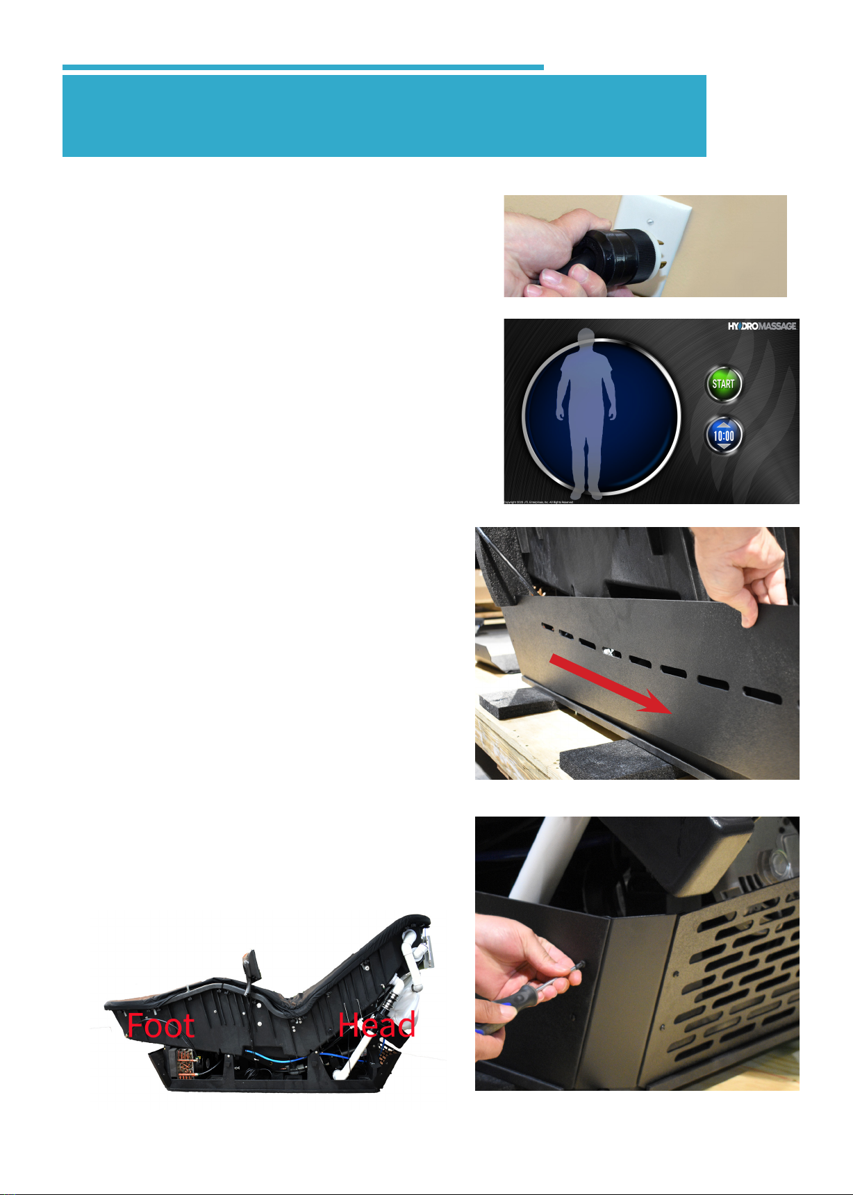
• Locate the 220 volt power cord and plug the
unit in. Wait for the initialization to complete.
Step
3.1
• While laying on the unit, press the START
button. The unit will start and begin a
massage session. Raise and pressure
from 1-10 and back to 1, press STOP 2x
and then restart, leaving on pressure 1.
While doing so, continuously check for
leaks. Reinstall the panels.
NOTE:Water Temp Cold error will appear
during and after initializing phase if water is
below 70°. Message will continue to appear
until temperature is raised to above 72°. To
warm the water, *always with someone lay-
ing on the unit*, raise the pressure level to
10 and run for 20-30 minutes.
• Starting at the head end of the unit,
reinstall the head end base panel
and secure with 2 screws as shown
at each head corner of the base
panels.
• Reinstall the 2 side base panels as
shown.
• IMPORTANT:: Be sure when rein-
stalling side panels, the slotes are curv-
ing up going towards the foot end.
3.0 Test Unit & Reinstall Panels

8
• Reinstall both side panels by lining the
panel cutouts with the at bar knobs and
apply pressure inward to engage panel
locks on at bar knobs.
• Install foot panel by lining the knobs with the
panel cutouts.
*Pro Tip:Holding the foot panel
in place, loosely attach with top panel
screws into the clipsto keep panels in
place, repeat step for opposite side pan-
els Securely fasten all 4 screws once all
panels are in place.
Step
3.5
Step
3.6
IMPORTANT: Be sure the front base
panel with the lter is reinstalled on the front
when reassembling..
• Reinstall the foot end base panel and
secure with 2 screws as shown at
each foot corner of the base panels.
Step
3.7

9
IMPORTANT
PRIOR TO LEAVING THE SITE
****GET CUSTOMER ACCEPTACE SIGNED****
ENSURE THAT ALL PANELS ARE
SECURED WITH SCREWS AND ALL
PACKING MATERIAL IS REMOVED
END OF DELIVERY AND UNPACKING
AND SETUP INSTRUCTIONS
Step
3.8
• Install back panel by centering panel with
head of unit
NOTE: Ensure panel cutouts line up with
at bar knobs.
• Install the remaining screws into panels and
thread them into panel clips.
For any issues during installation, contact HydroMassage®
technical support BEFORE LEAVING:
Email: [email protected]
Phone: 727-536-5566, option 1 at the prompt
For complete maintenance documentation and resources for your HydroMassage®
visit www.myhydromassage.com
Step
3.9

10
Step
1
Optional User Right Hand Touchscreen Installation
Only Perform the following steps if you are switching Touchscreen from the user left side.
Step
2
• Flip the bracket around 180° as shown,
making sure to set the stop pin in the
corresponding hole. Reinstall the bolt
and tighten with 7/16” wrench. Arm
should match the orientation shown
(WIRE HARNESS WILL NEED TO BE
MOVED UNDER THE TANK TO THE
RIGHT SIDE). Replace back cover .
Continue with Step 2.6.
Step
3
• Place the Touchscreen face down on the
top of the unit as shown with the arm stop
facing up. Using the 7/16” wrench remove
the bolt.
Tool needed, 7/16” wrench, Phillips Screwdriver
• Using a Phillips Screwdriver, remove the
center screw holding the back cover in
place.
Table of contents
Other HydroMassage Massager manuals