1
Remote Heater System has been designed to be installed safely either indoors or outdoors, remote
installation. It’s weather-tight construction helps to guard against the elements and allows for a variety of mounting
possibilities.
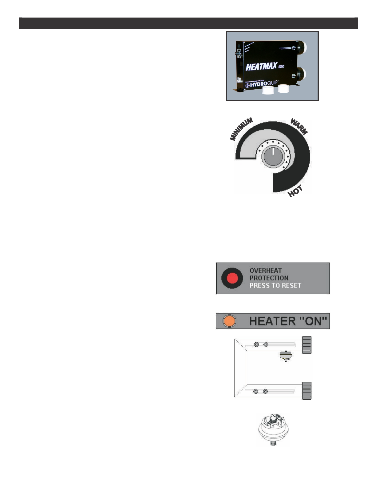
Your Hydro-Quip
Remote Heater System is totally self contained to insure trouble free installation and operation. As with
all electrical devices, certain safety precautions should be taken during installation and operation.
IMPORTANT SAFETY INSTRUCTIONS
READ AND FOLLOW ALL INSTRUCTIONS
DANGER – To reduce the risk of injury, do not permit children to
use this product unless they are closely supervised at all times.
WARNING – RISK OF CHILD DROWNING. Extreme caution must be
exercised to prevent unauthorized access by children. To avoid
accidents, ensure that children cannot use a spa or hot tub unless
they are supervised at all times.
DANGER – To reduce the risk of injury to persons, do not remove
suction fittings.
Spa location must accommodate sufficient drainage of water around
the base of the structure. as well as the power source compartment.
Prolonged immersion in water that is warmer than normal body
temperature can result in a dangerous condition known as
HYPERTHERMIA. The causes, symptoms, and effects of hyperthermia
may be described as follows: Hypert hermia occurs when the internal
temperature of the body reaches a level several degrees above the
normal body temperature of 98.6°F. The symptoms of hyperthermia
include dizziness, fainting, drowsine ss, lethargy, and an increase in
the internal temperature of the body. The effects of hyperthermia
include (1) unawareness of impendin g hazard, (2) failure to perceive
heat, (3) failure to recognize the need to exit sp a, (4) physical
inability to exit spa, (5) fetal damage in pregnant women, (6)
unconsciousness resulting in danger of drowning. WARNING – The
use of alcohol, drugs or medication can greatly increase the risk of
fatal hyperthermia in hot tubs and spas.
DANGER – RISK OF ELECTRICAL SHOCK. Install at least 5 feet
(1.5m) from all metal surfaces. (A spa may be installed within 5 feet
of metal surfaces if each metal su rface is permanently connected by
a solid copper conductor attached to the wire connector on the
terminal box that is provided for this purpose. Refer to NEC and local
codes in effect at the time of installation.)
A pressure wire connector is provided on the RHS control box to
permit connection of a solid copper bonding conductor between this
point and any equipment, metal encl osures of electrical equipment,
metal water pipe, or conduit within 5 feet (1.5m) of the unit as
needed to comply with local requirements.
•Bond accessible metal to the dedicated connector on the equipment
grounding bus, bond the equipment ground bus to the local common
bonding grid as part of the installation in the form of (1) a reinforced
concrete slab for support, (2) a ground plate provided beneath the
hot tub or spa, or (3) a permanent ground connection that is
acceptable to the local inspection authority.
DANGER – RISK OF ELECTRICAL
SHOCK .Do Not permit any
electrical appliance, such as a light, telephone, radio, or television,
within 5 feet (1.5m) of a spa or hot tub.
To reduce the risk of injury:
a) The water in a spa or hot tub should never exceed 104°F (40 °C).
Water temperatures between 100 ° (38°C) and 104 °F (40 °C) are
considered safe for a healthy adult. Lower water temperatures are
recommended for extended use (exceeding 10 – 15 minutes) and for
young children.
b) Excessive water temperatures have a high potential for causing fetal
damage during the early months of pregnancy, pregnant or possibly
pregnant women should limit spa or hot tub water temperatures to
100°F (38°C).
c) Before entering the spa or hot tub, the user should measure the
water temperature with an accurate thermometer.
d) The use of alcohol, drugs, or medication before or during spa or hot
tub use may lead to unconsciousness with the possibility of
drowning.
e) Persons suffering from obesity or with a medical history of heart
disease, low or high blood pressure, circulatory system problems, or
diabetes should consult a physician before using a spa or hot tub.
f) Persons using medication should consult a physician before using a
spa or hot tub since some medication may affect heart rate, blood
pressure, and circulation.
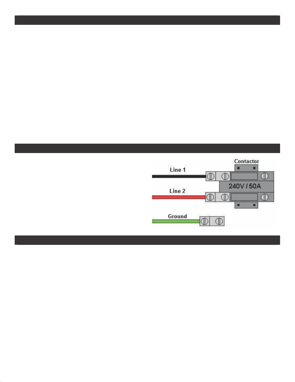
For Permanently Installed Units
A terminal marked “G” or “ground” is provided in the wiring box
located inside the equipment compartment. To reduce the risk of
Electric shock, connect the terminal or connector to the grounding
terminal of your electrical service or supply panel with a continuous
green insulated copper wire in accordance with National Electric
Code Table 250-95 and any other local codes in effect at the time of
the installation.
For Permanently Installed Units not Provided with
an Internal Disconnecting Method
The electrical supply for this product must include a suitably rated
Switch or circuit breaker to open all ungrounded supply conductors to
comply with Section 422-20 of the National Electric Code, ANSI/NFPA
70 –1987. The disconnecting means must be readily accessible to the
tub occupant but installed at least 5 feet (1.5m) from the tub water.
The electrical supply for permanently installed equipment must also
include a suitably rated Ground Fault Circuit Interrupter (GFCI) to
comply with article 680-42 of the National Electric Code, ANSI/NFPA
70.
SAVE THESE INSTRUCTIONS
INTRODUCTION
Your Hydro-Quip
•
•
•
•
•
•
•
•
•
•
IMPORTANT INSTALLATION REQUIREMENTS
ŸWhen plumbing/installing this heater DO NOT install a shut-off valve
on the discharge/pressure side of the system. A check valve that does not
have a shut off feature may be used to aid in servicing if desired.
ŸThe user MUST always disconnect the power supply to the heater
when draining the pool, spa or heater.
ŸThis heater must never be operated with the pump turned off.