三、
ͺ
: , : , : ;单位
; ;
; ;
:
P01:
P02:
P03:
P04:
P05:
P06:
P07:
11 12
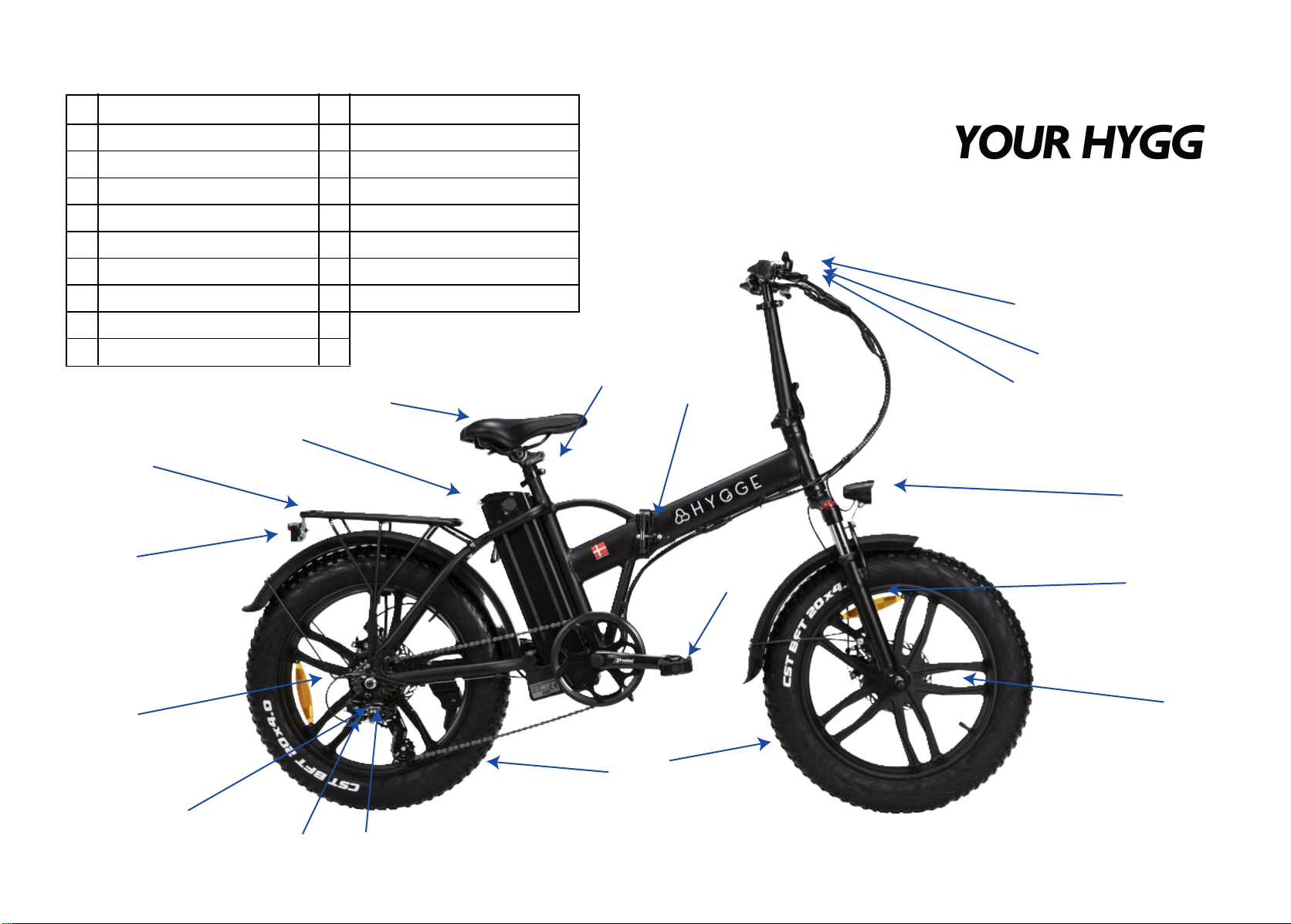
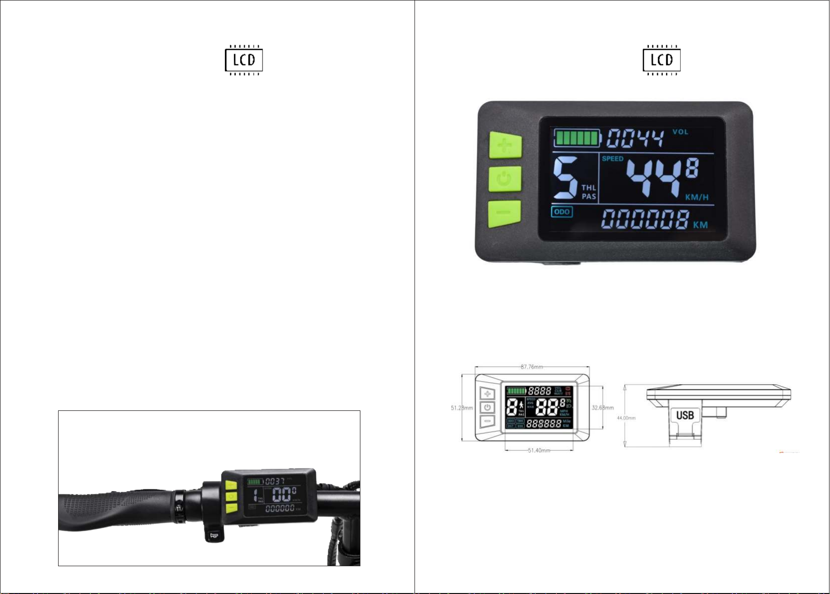
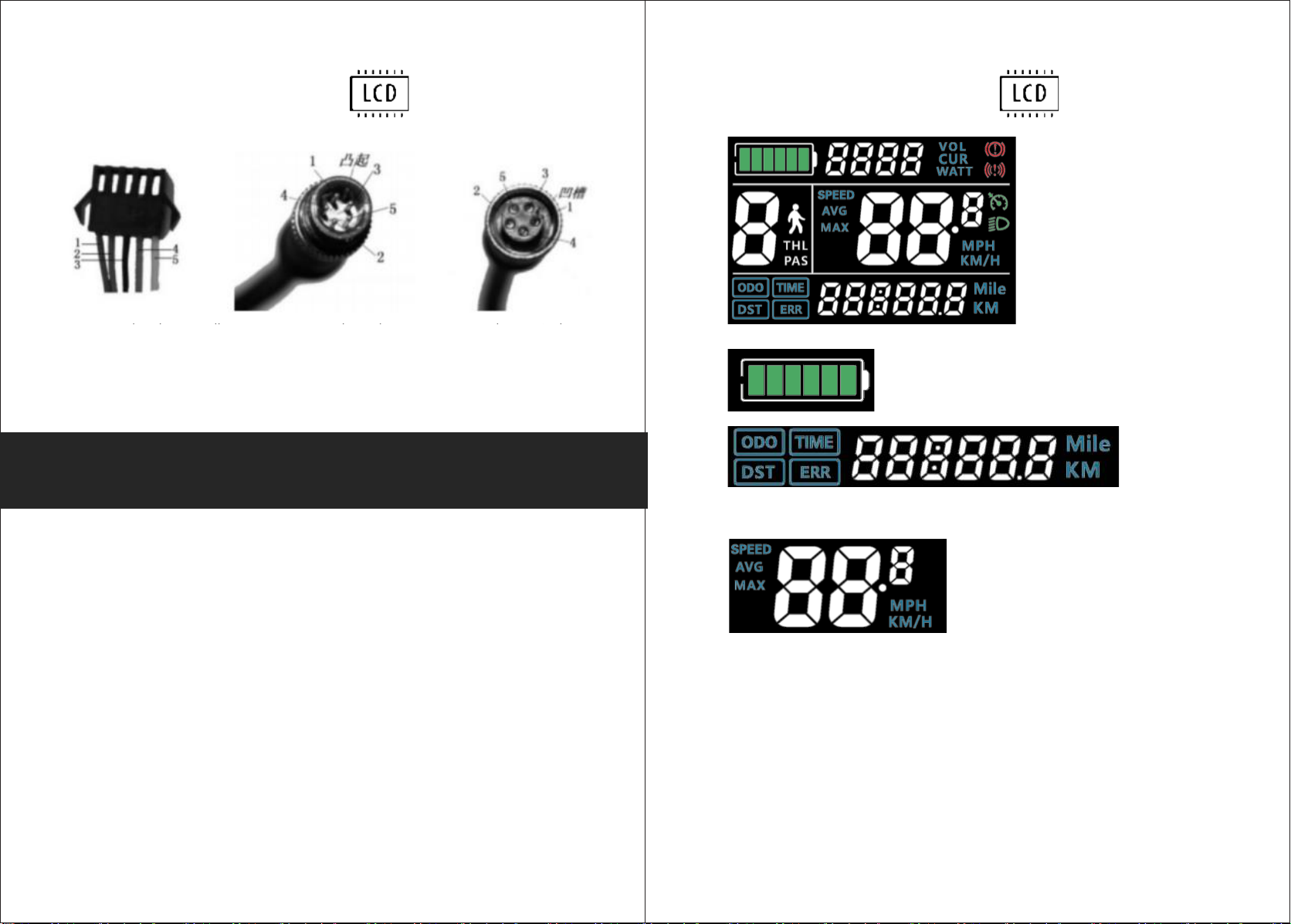
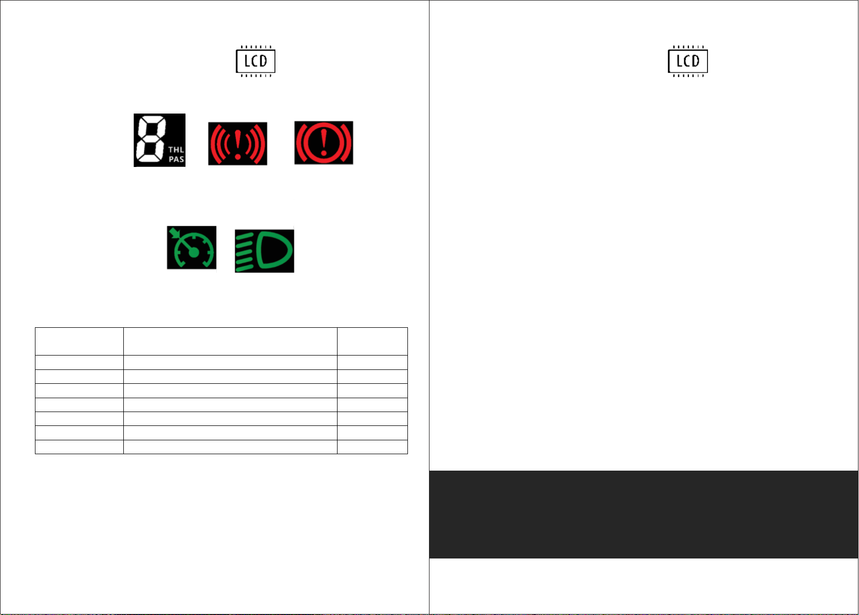
LCD DISPLAY LCD DISPLAY
• Zero start, non-zero start seting, 0:zero start; 1: Non-zero start;
• The drive mode is set 10 0: Power Drive (how much power is output is deter
mined by the power file bit, and the switch is invalid).
• Electric drive (by turning the handle drive, when the power file bit is invalid).
• Power Drive and Electric Drive co exixtence
• Help sensitivity setting range: 1-24;
• Help start intensity setting range: 0-5;
• Power Magnetic Steel Disk type setting 5, 8, 12 Magnetic Steel types
• Controller undervoltage
• ODO zero setting length press key 5 seconds 0D0 zero
• No enabling cruising, 1: enabling cruising; Automatic curise optional (valid for
protocol 2 only)
• Display speed ratio adjustment range: 50% ~ 150%
• 0 power bit, 0; 0, 1: does not include 0
• Protocol 1:5 S Protocol 2: Standby 3: Standby
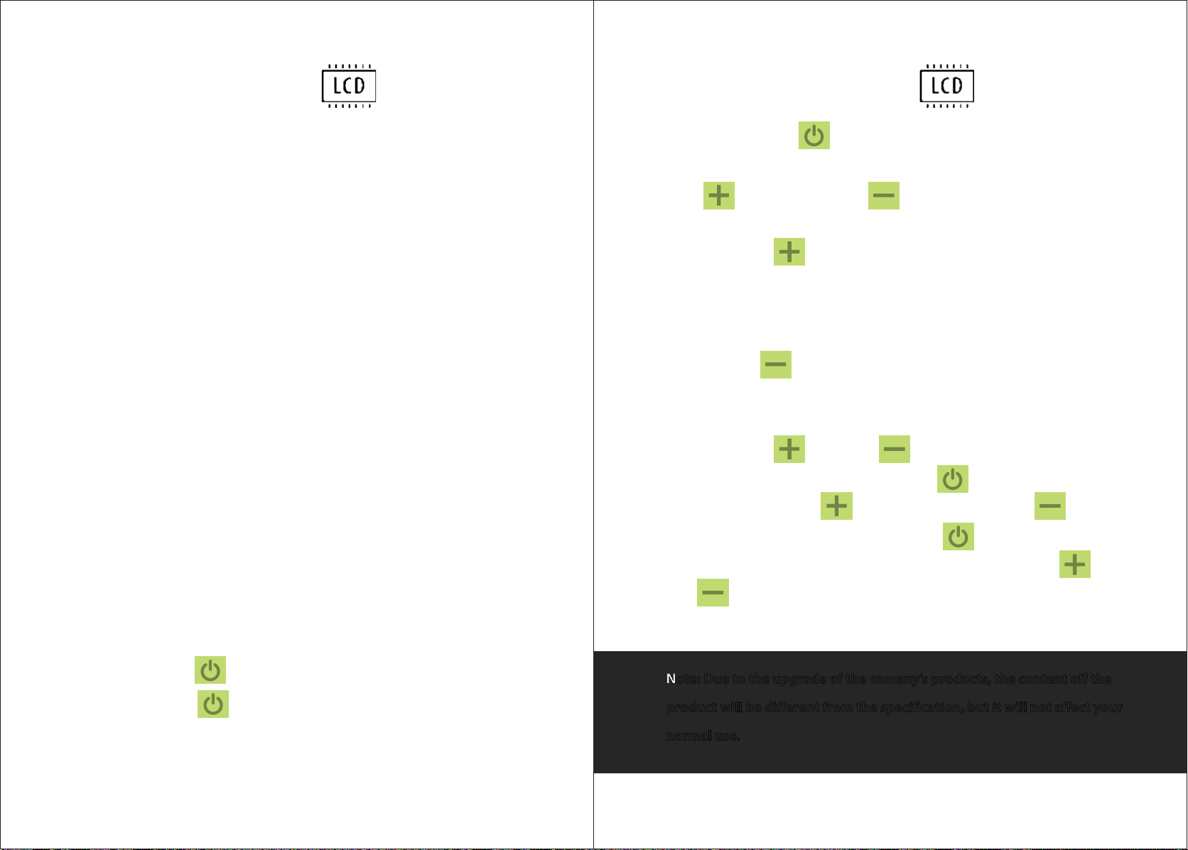
• Press and hold the button to start the display when the display is OFF.
After power-on, press button to switch between ODO, DST and TIME.
• Press and hold the button to shut down the display when the display is
on.
Press button, PAS+1. Press button, PAS-1.
• Press and hold button to turn on/off the headlight under the normal
display speed interface.
• Under the interface of normal speed display, when the vehicle is stationary,
press and hold button will enter 6km/h in walk mode,
and then let go and exit.
• Press and hold button and button enter Settings parameter value
modification: Under a parameter state, press button
switch parameters, press button value plus one, press button
value minus one and when its modified, press button swtich to the next
parameter and save the previous parameter value; Press and hold button
and button again to save and exit te settings. If not, wait 8
seconds to automatically exit and save the parameters.
Note: Due to the upgrade of the comany’s products, the content off the
product will be different from the specification, but it will not affect your
normal use.
Key Introduction