Growatt THOR 11AS-S/P User manual

3-phase AC charger quick installation guide
Growatt THOR 11AS-S/P
Growatt THOR 22AS-S/P
No.28 Guangming Road, Shiyan, Bao’an District, Shenzhen, China
Growatt New Energy Co.,Ltd
T
E
W
+ 86-755-27471900
info@ginverter.com
www.ginverter.com

Thank you for using Growatt EV charging pile!
Disclaimer
This user manual is copyrighted by Growatt New Energy
Co.,ltd.(Hereinafter referred to as “Growatt”). No company or person
may extract or copy part or all of this user manual without the written
permission of Growatt. Content must not be transmitted in any form,
including materials and publications.
All rights reserved. Growatt has the final right to interpret this user
manual. The information in this manual is subject to change without
notice.
THOR series intelligent single-phase AC charger is a power supply device
that uses professional and advanced technology to provide energy supply
to electric vehicles, it also has a friendly man-machine interface and
versatile functions of control, billing, and communication. The charger can
be connected to a back-office server to realize the functions of reservation
and payment via Mobile phone APP. Diversified communication options,
including wired Ethernet, WIFI, 4G is available for back-office server
connection.
We sincerely hope that this product can meet your needs and will
continuously improve the quality of our products.
Menu
I. Product description ·········································································
II. Packing list ·················································································
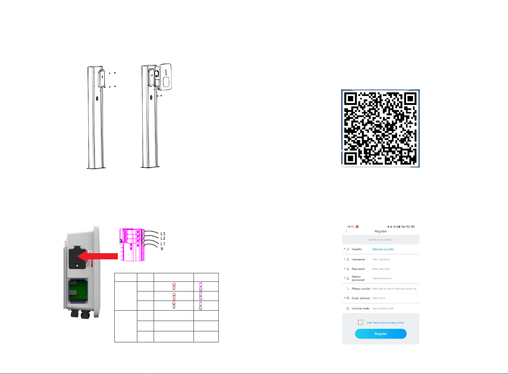
III. Installation and wiring ···································································
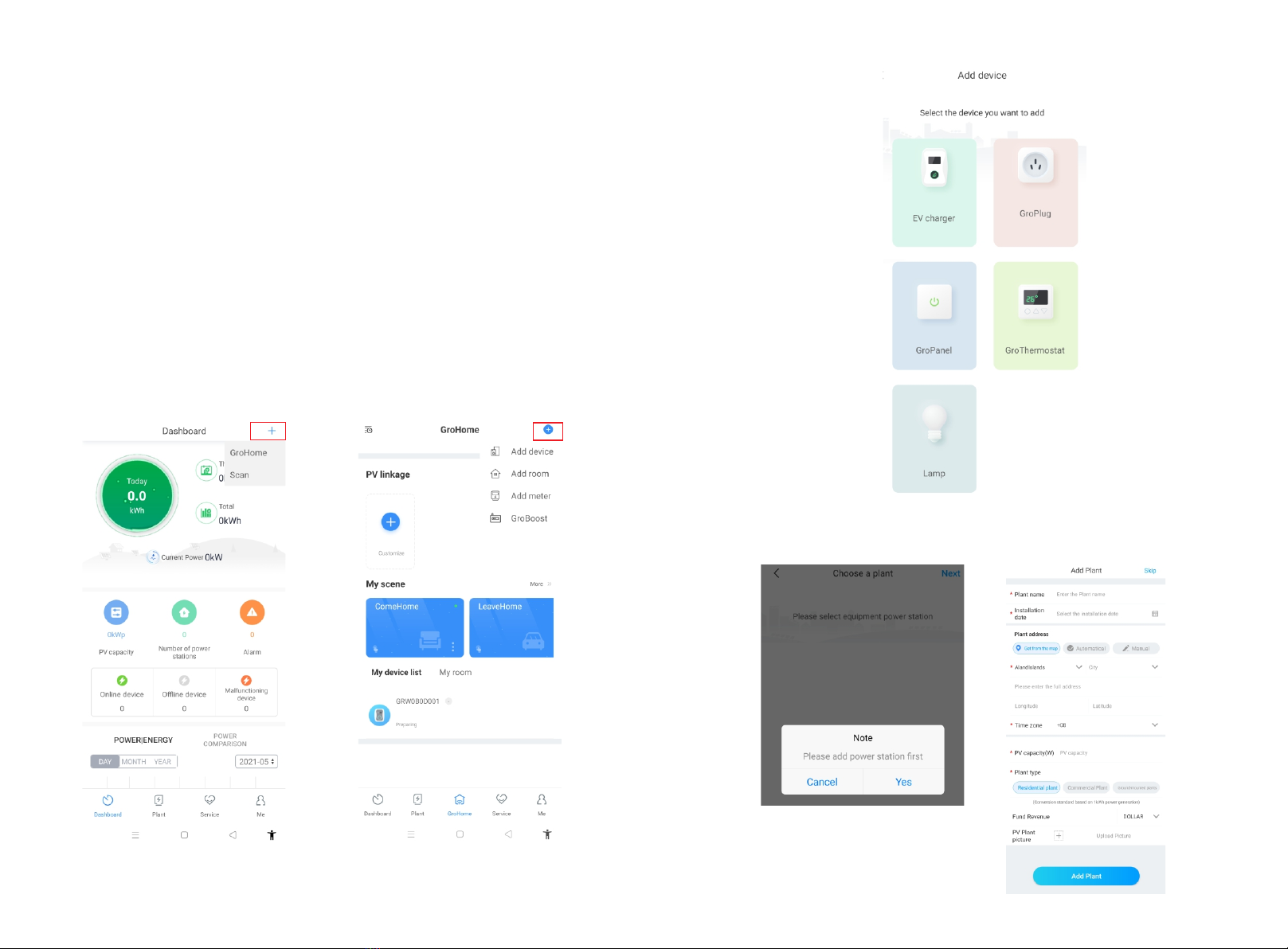
IV. APP download, register, and login ···················································
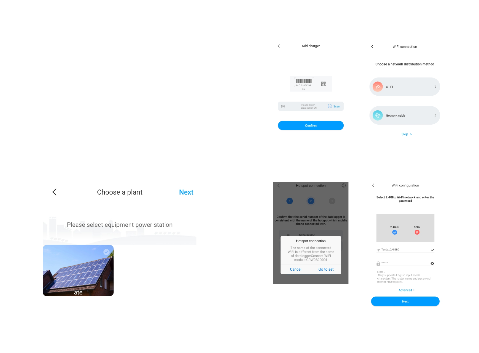
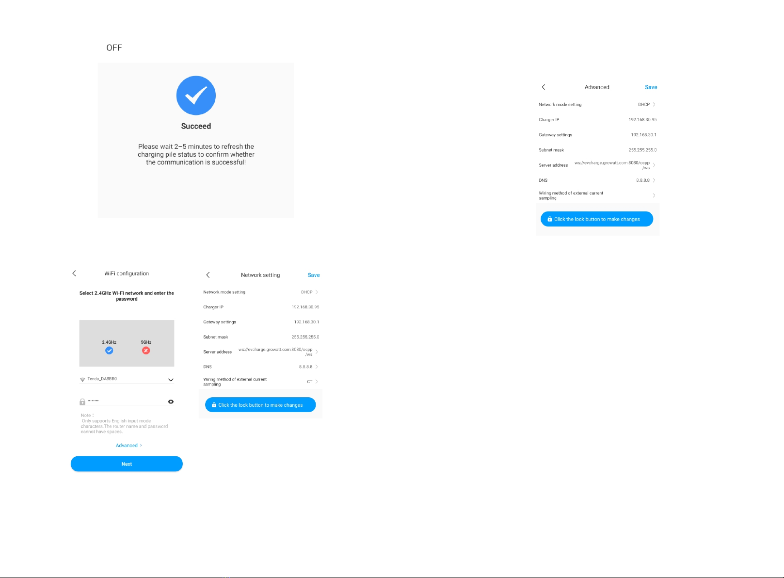
V. EV Charger Internet Configuration ·················································
VI. Operation instruction and LCD description······································
VII. EV Charger Work Modes ······························································
VIII. Other Settings ··········································································
IX. Record····························································································
X. Data ·······························································································
XI. Troubleshooting ·············································································
1
3
4
8
13
24
28
39
41
43
44
XII. Specification ·················································································
XIII. Annex ····························································································
45
46

I. Product description
12
Wiring definition in the side window
1
3
2
4
5
6
7
8
1
2
3
1. LOGO and LOGO backlight;
2. Status indicator
(Indicator flashes when charging);;
3.Emergency stop button+
Forced on/off button;
4. Socket outlet(plug holder for
cabled version);
5. Mounting bracket;
6. Side window and nameplate;
7. Waterproof cable gland for
communication wires;
8. Waterproof cable gland for
AC input cables
1. Terminal block for CT/meter wiring. The terminal definition is:
①A; ②B; ③I; ④GND.
① and ② is RS485 terminal for meter connection;
③ and ④ is for CT connection.
2. AC input terminals. Terminal definition is (①N; ②L).
3. CAN communication terminal

II. Packing list
No. Name Qty Remark
1
2
3
4
1
1
1
1
Charger
User manual
Quality certificate
Mounting bracket
5
6
7
Cable hook
ST6.3X40
Stainless steel hex-head
self-drilling screws
12X46
Plastic expansion plugs
1
4-7
4-7
For cabled version
4 for socket version, 7 for cabled
version(3 of the 7 screws is for
cable hook fixing)
4 for socket version, 7 for cabled
version(3 of the 7 plugs is for
cable hook fixing)
4
3
8User card 1RFID function will be equipped
with user card
III. Installation and wiring
3.1.1 Open the package, you’ll see a charge point, a mounting bracket, a user manual and a
bag of mounting accessories. There is also an RFID card if the charge point is RFID version.
For cabled version, a cable hooker is also included inside.
3.1 Mount on a wall
3.1.2 Remove the mounting bracket from the charge point, use it as a template to mark the
position of the drill holes. Drill the holes and hammer the expansion bolts in the accessories
bag into the holes. Then fix the mounting bracket onto the wall.

3.1.4 Crimp the below shown insulated ferrule or ring terminals on the end of the AC input
wires. Connect the wires into the terminal block of the charge point as below. Check the
wiring and then close the RCBO in the side window. Close the side window with the cover,
then the wring is done.
3.2 Mount on a pole
3.2.1 Open the package of the pole, take out the pole and mounting accessories.
3.2.2 The pole must be installed on a hard surface, concrete surface is recommended, it can
also be mounted on a solid ground. Drill hols according to the requirements marked on the
illustration for fixing expansion bolts.
3.2.3 Fix the pole onto the holes with expansion bolts. The input cables shall go into the pole
from the bottom middle area and come out of it from the area below the cable hooker.
3.1.3 Put the charge point onto the bracket, and fix it with the 2 screws at the bottom of the
charge point. The installation is done.
56
Terminal
Wire
Model L1/L2/L3/N PE
11K
22K
44K
11K
22K
44K
2
≧2.5mm
≧AWG12
2
≧2.5mm
≧AWG12
2
≧6mm
≧AWG9
2
≧6mm
≧AWG9
2
≧16mm
≧AWG5
2
≧16mm
≧AWG5

3.2.4 Fix the mounting bracket onto the pole.
3.2.5 Position the charge point onto the bracket and secure it on the bracket with the 2
screws.
3.2.6 Crimp the below shown insulated ferrule or ring terminals on the end of the AC input
wires. Connect the wires into the terminal block of the charge point as below. Check the
wiring and then close the RCBO in the side window. Close the side window with the cover,
then the wring is done.
78
Terminal
Wire
Model L1/L2/L3/N PE
11K
22K
44K
11K
22K
44K
2
≧2.5mm
≧AWG12
2
≧2.5mm
≧AWG12
2
≧6mm
≧AWG9
2
≧6mm
≧AWG9
2
≧16mm
≧AWG5
2
≧16mm
≧AWG5
IV. APP download, register, and login
4.1 APP download
Users can scan the QR code (Android and IOS ) with the WeChat, or go to the App
Store and Google Play to search for ShinePhone or log in to our monitoring
website server.growatt.com or server-cn.growatt.com to download.
4.2 Register
Before using ShinePhone APP first time, the user must register an account in advance.
There are three steps when users register the account:
(1) Fill in the account registration information.

9 10
a) When customers add plant, they need to fill in the name of the plant (required),
installation date (required), national city (required), detailed address (optional), time zone
(required), PV capacity (required), plant type (required, Household plant/ /Commercial
plant/Ground plant), fund income (optional), plant picture (optional, when the user does not
upload pictures, a default plant picture will be given).
b) There are three ways to fill in the plant address, map selection, automatic acquisition, and
manual input.
Map selection, users can select any location on the map, then the detailed location will be
filled automatically of the country.
Automatic acquisition, through satellite positioning, obtain the current location of the user,
then the detailed location will be filled automatically of the country .
Manual input, the user manually inputs the country, city and detailed address.
c) This page can be skipped. After skipping, the user registration account will be logined
directly, enter the APP plant page. Skipping the process of adding plant, the default plant will
not be generated. When enter the APP plant page, the system will remind the user to add
the plant.
a) Fill in the account information. To fill in the account information, you need to select the
account country (required), fill in the user name (required), password (required), confirm
password (required), telephone (required in China, optional for other regions), email (optional
in China, required for other regions), installer code (optional).
b) The user terms must be checked manually to agree before registering, all required fields
must be filled in before registering.
(2) Add Plant
4.3 Sign in and log out

11 12
The user can log in the APP through the existing account and password. The system
automatically determines the account's attributes and distributes the server. The ShinePhone
system is divided into China and Worldwide servers.
After the users log in successfully, for the next time log in, you can directly select the account
number from the information the phone remembered.
If you have any questions about the password, or if you enter the wrong password, you can
click the eye icon on the right side of the password input box to view the password, and click
the password again to hide it.
4.4 EV Charger Internet Configuration
For new users, please click the "+" in the upper right corner of the overview, select
“GroHome” and add device (EV Charger), for users who already have had “GroHome” page,
go to the “GroHome” page directly and click the "+" in the upper right corner to add device
(EV Charger).
If the users haven’t built the “power plant” before and click “add device”, the app will
remind you to add a plant firstly, and the app will allow to “add device” after finishing filling
the information of the plant.

14
13
5.1 WiFi Configuration
a)Choose a related power plant after adding the device (Note: a power plant is required to
build before adding the EV Charger).
b)Enter the serial number of the EV charger or scan the Bar/QR code to add the EV charger
c)Select “WiFi” for network configuration.
d)Enable the “WLAN” in the setting and connect to the “WIFI” whose name is consistent
with the serial number of the EV charger, then enter the WiFi password (default WiFi
password is: 12345678) and click “next”.
e)Enter the WiFi name and password of your router (the connected WiFi is required 2.4GHz
WiFi, and the network should be available), and then click “Next”.
f) Please wait 2-5 minutes and refresh the EV charger status to confirm whether the
communication is successful.
Note: If the EV charger has been configured before, and don’t need to configure the network
again.
V. EV charger Internet configuration

16
15
Advanced Setting
If the EV charger has an external current sensing device, then it click the “advanced” in the
WiFi configuration page, it needs to choose the corresponding configuration (CT or meter
type, choose the right brand of the meter type, Acrel or Eastron).

17 18
5.2 Network Cable Connection Configuration
a)Choose a related power plant after adding the device (Note: a power plant is required to
build before adding the EV Charger. Enter the serial number of the EV charger or scan the
Bar/QR code to add the EV charger.
b)Select “Network Cable” for network configuration.
c)Click “cancel” and the network will be connected dynamically based on the dynamic IP
mode.
d)Waiting for 2-5 minutes which EV charger will refresh its status, and confirm whether the
communication is successful.

19 20
Note: If the users want to set the static IP mode
1.Click “go to set” during (d) step and make sure the network cable is disconnected
2.Do the hotspot connection, connect to the WiFi whose name is consistent with the series
number of EV charger, and enter the default password:12345678.
3.Make sure the parameters of IP and getaway are the same as that of the router and click
“next”.
4. Connect the network cable and wait for 2-5 minutes which EV charger will refresh its
status, and confirm whether the communication is successful.

2221
5.3 4G Configuration
If the EV charger is a 4G model, then the user can click the “skip” directly during the page of
network configuration methods.
5.4 AP Mode Configuration
If the network connection is abnormal, the users can use the AP mode to reset the network
or do some basic setting.
a) Click the AP mode, and enter the hotpot connection, click “next” to switch to other
pairing mode.
b)Connect the WiFi whose name is consistent with the series number of the EV charger and
click next.
c)User can check the basic information, and do some basic parameters setting like network
setting, sever setting and EV charger setting.
d)After that, waiting for 2-5 minutes which the EV charger will refresh its status.

23 24
6.1 Charging mode and Operation
User can go to the “setting” page and click the “EV charger setting”, users can set the
charging activation way like APP, RFID, plug and charge.
VI. Operation instruction and LCD description
Initiate or cease charging by using APP or by swiping RFID card. You can also use APP for
reservations and choose the work mode you need.
APP/RFID mode:

25
RFID mode:
Charging can only be initiated or ceased by swiping RFID card.
RFID mode operation process flow
Plug&Charge:
Charging will start automatically after EV plugged in. If you want to stop the charging, just
press the forced on/off button on the side of the charger.
Plug&Charge mode operation process flow
26
5.2 LCD interface introduction
Interface of standby status.
Charging mode is displayed at
the bottom centre of the screen.
Interface of user card information
Displayed for user to check card ID
and balance when swiping RFID
card while EV is not connected
Interface of charging status.
Displayed when the charging is
being carried out. There is charging
time, consumed electricity,
charging cost on it, as well as
real-time charging voltage and
charging current.
Interface of charging complete.
Displayed when the EV stops
charging, or forced on/off button
is pressed on charger side.

27
Interface of billing.
After scanning QR code or swiping
RFID card for billing, this interface
will open up to display user
ID/charging time/cost/balance,
etc.This interface will also come
out when you stop charging on
the Growatt APP or when you
press the forced on/off button
or unplug the gun at
Plug&Charge mode.
Interface of fault status.
Displayed with fault code and fault
description when fault occurs.
Interface of reserved status.
If the back-office server and APP
support reservation function and
the charger is reserved, this
interface will come out showing
user ID and remaining time to
reserved time.
28
VII. EV Charger Work Modes
7.1 Fast Mode
Plug&Charge:
Click “charge” directly and the EV will be charged at maximum power coming from a
renewable energy source or simply from the grid, especially quickly if you’re in a hurry, and
support multiple control strategies of timer, charging capacity, charging budget.
Note: the reservation function only can be set when the EV charger is in idle status.

29 30
Time Reservation
It can be divided into charging time and charging period reservation, users can set when it
will start to charge and how long the charging will continue, also can enable “every day” to
make it work following that strategy to work all the time.
Charging Capacity Reservation
Users can set the target charging capacity(kWh) and the start time through clicking
“energy”, and also can enable “every day” to make it to work following that strategy to
work all the time.
Charging Budget Reservation
Users can set the target charging budget and the start time through clicking the “cost”, and
also can enable “every day” to make it to work following that strategy to work all the time.

31 32
7.2 PV Linkage Mode
Introduction
Driven by solar, charge your car with renewable energy, the EV will be charged by the surplus
solar power dynamically, combining PV and EV charger together to maximize the solar self-
consumption rate and cut your bill.
Note: The EV should connect with the EV charger, and the PV Linkage mode will be
automatically activated when the solar power is sufficient.
Wiring
To monitor the real-time power import and export, a CT or meter is needed for this function
to work properly.
If CT is used, the wiring will be as below,
8.3 If meter is used, please wire it as below

33 34
APP Operation
The PV linkage mode require the EV charger to connect with an external current sensing
device, and choose the corresponding configuration (CT or meter type, choose the right
brand of the meter type, Acrel or Eastron).
Function of importing from the grid
Disable the function of importing power from the grid.
The EV will be charged dynamically only by surplus solar power when the surplus solar power
is greater than Min. operation power*, When surplus solar power is lower than Min.
operationpower, then the EV charger will stop charging .
Enable the function of importing power from the grid set the max. importing value
The EV will be charged dynamically only by surplus solar power when the surplus solar power
is greater than *Min. operation power, when surplus solar power is lower than *Min.
operation power, the EV charger will use grid power to offset the shortage part and keep
charging at Min. operation power.
Note: *Min. operation power: 1.4kW for single-phase EV charger, and 4.1kW for three-phase
EV Charger.
Boost Function
Manual Boost Function
It is useful if users arrive home with an almost empty battery and users want to charge the
EV quickly to ensure enough energy for a short trip when the solar energy is insufficient
While users enable the manual boost function and set “start time” and “end time”, the EV
charger will charge the EV at its max. power during a set period even drawing the power
from the grid, after that, it will recover back to the normal PV linkage mode.

36
Smart Boost Function
It’s useful to guarantees EV’s battery capacity before a set time when the solar energy is
insufficient.
While users enable the smart boost function and set “Pick-up time” and “Preset electricity”,
the EV charger will charge the EV with a target kWh figured by a set time, it may draw the
power from the grid to guarantee the EV’s battery capacity when the solar energy is
insufficient.
Example: if the users enable smart boost and set the “pick-up time” is 22:00, and “preset
electricity” is 20kWh. In sunlight hours, the EV has been charged by surplus solar energy with
the only 10kWh of charge accumulated, because users activated the smart boost, then the
THOR EV Charger will automatically boost the charge to the required 20kWh by 22:00 even
taking power from the grid.
7.3 Off-peak modes
Introduction
Once enable the Off-Peak mode, the EV charger will automatically charge the EV when it’s at
off-peak time to reduce the electricity bill. Users also can customize their low-rate charging
time in the off-peak mode page.
Note:
1. Users need to input the charging rates in the setting page manually before enabling off-
peak modes.
2. The EV should connect with the EV charger, and the off-peak mode will be automatically
activated at the low-rate charging time.
35
This manual suits for next models
1
Table of contents