EVBOLT APEX 10 User manual

Intellectual property of EVBOLT, Inc
Electric Vehicle AC Charger
APEX 10 –User Manual
EVB-AC-J10

Intellectual property of EVBOLT, Inc
Contents
1. Important Safety Instructions..........................................................................................................................................1
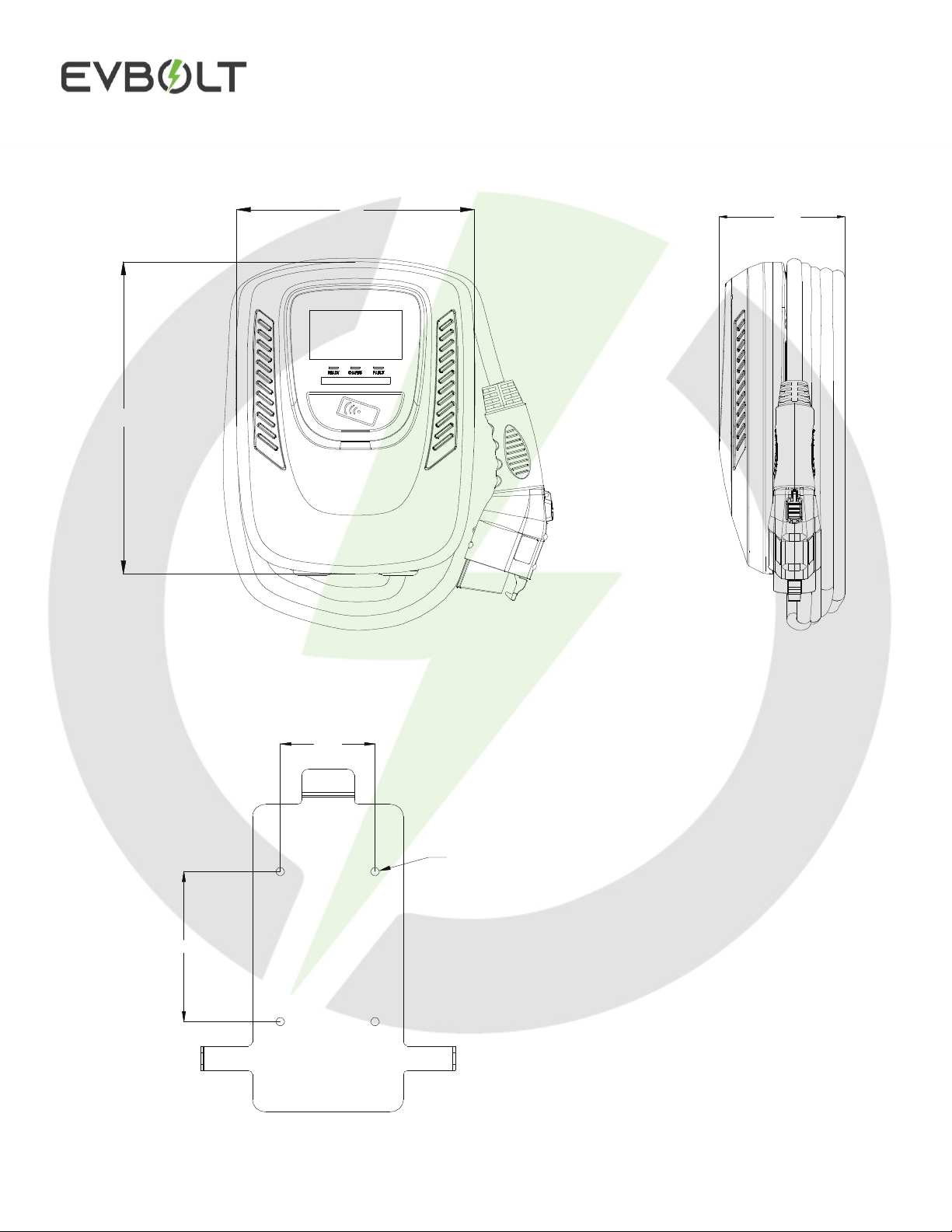
2. Dimensions .....................................................................................................................................................................4
3. Design Standards.............................................................................................................................................................5
4. Specifications..................................................................................................................................................................6
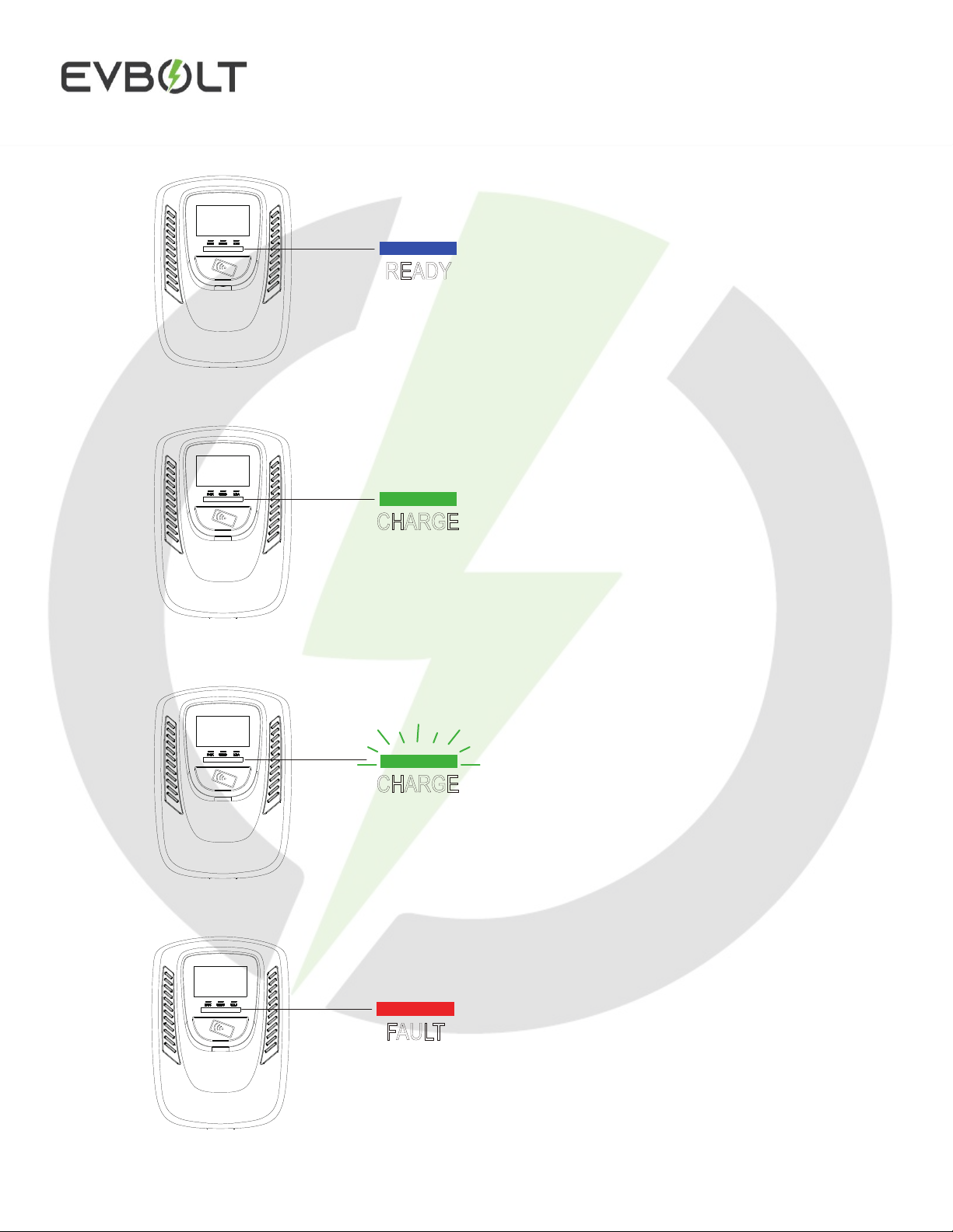
5. Status Description...........................................................................................................................................................7
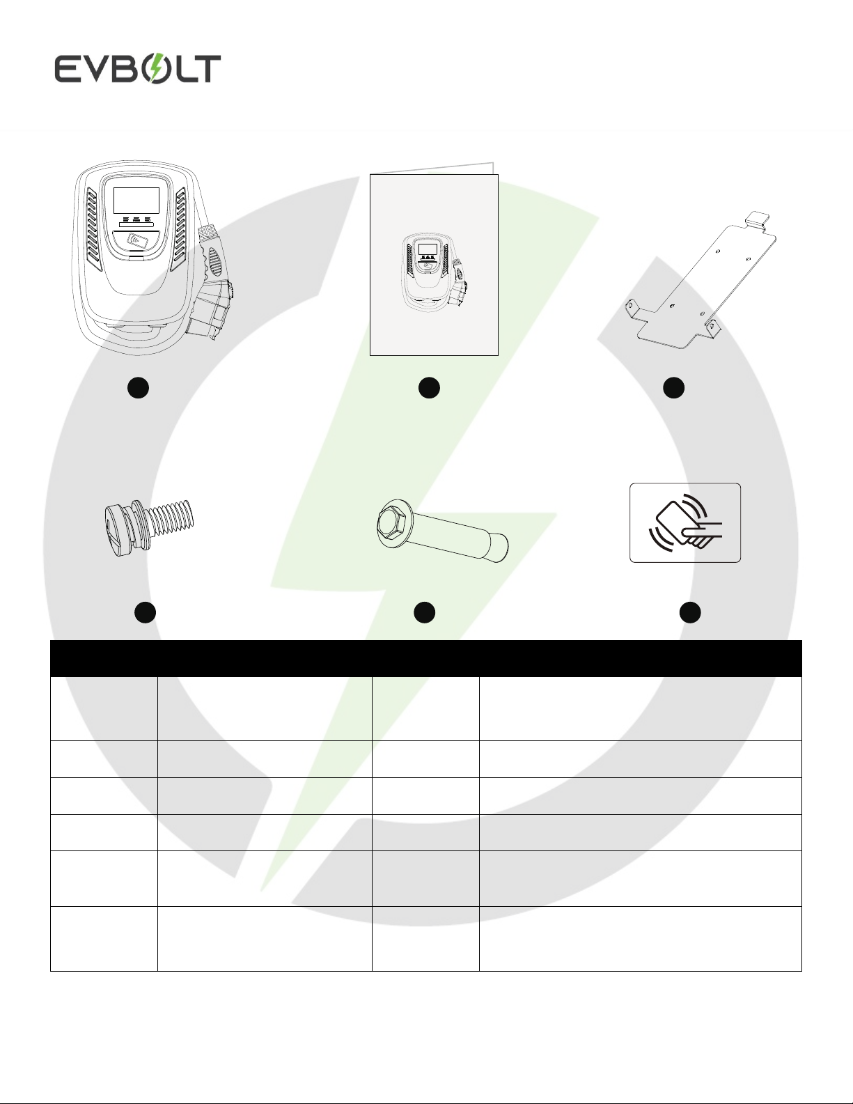
6. Packing list......................................................................................................................................................................8
7. Installation Instructions...................................................................................................................................................9
7.1 Safety Requirements...............................................................................................................................................9
7.2 Wiring...................................................................................................................................................................10
7.3 Tools and Materials Required...............................................................................................................................11
7.4 Wall-mounted Bracket Installation.......................................................................................................................12
8. Operation Instructions...................................................................................................................................................14
8.1 Operating Procedures............................................................................................................................................14
8.2 Operating Steps (ONLINE MODE)......................................................................................................................14
8.2.1 EVBOLT iOS/Android Application .............................................................................................................14
8.2.2 EVBOLT WebApp .......................................................................................................................................14
8.3 Operating Steps (OFFLINE MODE)....................................................................................................................15
8.4 Error and Warning Message .................................................................................................................................17
9. Maintenance and Repair................................................................................................................................................18
9.1 Daily Maintenance................................................................................................................................................18
9.2 Maintenance Spares ..............................................................................................................................................18
9.3 Warranty and Maintenance...................................................................................................................................19

Intellectual property of EVBOLT, Inc Page 1 of 19
1.Important Safety Instructions
WARNING –This manual contains important instructions for Models:
APEX 10 series that shall be followed during installation, operation, and maintenance of the unit.
•Read all the instructions before using this product
•This device should be supervised when used around children
•Do not put fingers into the electric vehicle connector
•Do not use this product if the flexible power cord or EV cable is frayed, has broken insulation, or has any
other signs of damage
•Do not use this product if the enclosure or the EV connector is broken, cracked, open, or shows any other
indication of damage
•To reduce the risk of fire, connect only to a circuit provided branch circuit overcurrent protection in
accordance with the CSA C22.1–15 Canadian Electrical Code, Part 1 (Canada) or NOM-001- SEDE
Electrical installations (utility) (Mexico) or ANSI /NFPA 70 National Electrical Code (USA)
Circuit Breaker Options Table
Output Amperage (A)
16
32
40
48
Circuit Breaker Options (A)
20
40
50
60
•To avoid a risk of fire or electric shock, do not use this device with an extension cord
•THE SUITABILITY OF THE USE OF FLEXIBLE CORD IN ACCORDANCE WITH CE CODE, PART
I, RULE 4-012, IS TO BE DETERMINED BY THE LOCAL INSPECTION AUTHORITY HAVING
JURISDICTION
•Risk of electric shock. Do not remove the cover or attempt to open the enclosure. No user-serviceable
parts inside. Refer servicing to qualified service personnel

Intellectual property of EVBOLT, Inc Page 2 of 19
This device complies with part 15 of the FCC Rules.
Operation is subject to the following two conditions:
This device may not cause harmful interference, and this device must accept any interference received, including
interference that may cause undesired operation
Caution: Changes or modifications to this unit not expressly approved by the party responsible for compliance
could void the user's authority to operate the equipment.
Note: This equipment has been tested and found to comply with the limits for a Class A digital device, pursuant
to part 15 of the FCC Rules. These limits are designed to provide reasonable protection against harmful
interference when the equipment is operated in a commercial environment. This equipment generates, uses, and
can radiate radio frequency energy and, if not installed and used in accordance with the instruction manual, may
cause harmful interference to radio communications. Operation of this equipment in a residential area is likely to
cause harmful interference in which case the user will be required to correct the interference at his own expense.
Wi-Fi module: Contains FCC ID: 2AC7Z-ESPWROOM32D
LTE module: Contains FCC ID: XMR202008EC25AFXD
To satisfy FCC RF exposure requirements, a separation distance of 20cm or more should be maintained between
the antenna of this device and persons during device operation. To ensure compliance, operations at closer than
this distance is not recommended.

Intellectual property of EVBOLT, Inc Page 3 of 19
SAE J1772
AC Charging
Connector
Rear Notch
Charging Cable Inlet AC Power Inlet
LAN Cable Inlet
LED Light
Indication

Intellectual property of EVBOLT, Inc Page 4 of 19
2.Dimensions
4.8″
4-Φ0.35″
2.83″
5.1″
9.8″
13.8″

Intellectual property of EVBOLT, Inc Page 5 of 19
3.Design Standards
UL 2594: Electric Vehicle Supply Equipment
UL 2231-1: Personnel Protection Systems for Electric Vehicle (EV) Supply Circuits: General Requirements
UL 2231-2: Personnel Protection Systems for Electric Vehicle (EV) Supply Circuits: Particular Requirements for
Protection Devices for Use in Charging Systems
UL 2251: Plugs, Receptacles and Couplers for Electric Vehicles
UL 62: Flexible Cords and Cables
UL 991: Tests for Safety-Related Controls Employing Solid-State Devices
UL 1998: Software in Programmable Components
NFPA 70 Article 625: National Electrical Code, Electric Vehicle Charging System UL 840 (Clearance and
Creepage)

Intellectual property of EVBOLT, Inc Page 6 of 19
4.Specifications
MODEL NAME
APEX 10 (EVB-AC-J10)
Rated Input Voltage
200-240 VAC / Single Phase
Rated Output Current
16/32/40/48 Amperes
AC Power Frequency
60 Hz
Input Protection
UVP, OVP, RCD, SPD, Ground Fault Protection
Output Protection
OCP, OTP, Control Pilot Fault Protection
Output Interface
SAE J1772 AC Charging Connector
Storage Temperature
-40°F to 158°F
Operation Temperature
-22°F to 122°F
Relative Operation Humidity
95% RH Maximum
Relative Storage Humidity
95% RH Maximum
Version
LAN + Wi-Fi Version / LAN + 4G Version
RJ45 Cable Inlet
10M/100M Base-T
Wi-Fi Function*
802.11 b/g/n
3G/4G Function**
LTE, GSM/GPRS
Cable Length
18ft
Protection Level
Type 3
Installation Type
Wall-Mounted
Altitude
≤ 6561ft
Status Indication
Red, Green, Blue LED
* Wi-Fi Version
** 4G Version

Intellectual property of EVBOLT, Inc Page 7 of 19
5.Status Description
Standby - Blue Light The READY
light stays steady in standby mode.
Waiting for Charging - Green Light After the
vehicle connector is connected to the vehicle
inlet, the CHARGE light is constantly lit.
Charging - Green Light
Flashing
Fault - Red Light
The red light is lit while fault. Please refer
to "9.3 Error and Warning Messages" for
detailed information.

Intellectual property of EVBOLT, Inc Page 8 of 19
6.Packing list
No.
Product Name
Quantity
Notes
1
AC Charger
(With Charging Cable)
1
2
User Manual
1
3
Wall-Mounted Bracket
1
4
M5 teeth screws
2
5
M6 Hexagonal Expansion
Screws
4
6
RFID Card
(RFID Version Only)
2
RFID
1
4 5 6
23
Electric Vehicle AC Charger
APEX 10 – User Manual
EVB-AC-J10

Intellectual property of EVBOLT, Inc Page 9 of 19
7.Installation Instructions
7.1 Safety Requirements
•Be sure to prevent the user manual and ensure local building and electrical codes are reviewed before
installing the AC charger
•The AC charger should be installed by a qualified technician according to the user manual and local safety
regulations
•Use appropriate protection when connecting to the main power distribution cable
•Type B, C or D breaker with the rating current for table should be installed in the upstream AC distribution
box
•Disconnect switch for each ungrounded conductor of AC input shall be provided by others in accordance
with the National Electric Code, ANSI/NFPA 70

Intellectual property of EVBOLT, Inc Page 10 of 19
7.2 Wiring
GROUNDING INSTRUCTIONS
This product must be grounded. If it should malfunction or break down, grounding provides a path of least
resistance for electric current to reduce the risk of electric shock. This product is equipped with a cord having an
equipment grounding conductor and a grounding plug. The plug must be plugged into an appropriate outlet that
is properly installed and grounded in accordance with all local codes and ordinances.
WARNING –Improper connection of the equipment-grounding conductor is able to result in a risk of electric
shock. Check with a qualified electrician or serviceman if you are in doubt as to whether the product is properly
grounded. Do not modify the plug provided with the product –if it will not fit the outlet, have a proper outlet
installed by a qualified electrician.
Circuit Breaker Options
Output Amperage (A) 16A 32A 40A 48A
Circuit Breaker Options (A) 20A 40A 50A 60A
For safe use of electricity, please add circuit breaker protection in the input
part of charging pile . Connect the L1 wire to the grid L1, connect the L2
wire to the grid L2, connect the PE wire to the grid PE (for all Version).

Intellectual property of EVBOLT, Inc Page 11 of 19
7.3 Tools and Materials Required
Tools required to install the Wall-Mounted charger:
•Wire stripper
•Phillips screwdriver for M5
•Slotted screwdriver for 4~5.5 mm
•Adjustable Wrench M6
•Head gasket screw 10-10.5 mm
•Voltmeter or digital multi-meter (for measuring AC voltage at the installation site)
•The inserting cable should meet the best waterproof performance. It is recommended to use 3
cores/7AWG cable (XLPE or equivalent cable) to pull the cable from the distribution box
•Level ruler
•Pencil or marker
•Machine drill
INSTALLATION INSTRUCTIONS
“This device shall be mounted at a sufficient height from grade such that the height of the storage means for the
coupling device is located between 600 mm (24 inches) and 1.2 m (4 feet) from grade.”

Intellectual property of EVBOLT, Inc Page 12 of 19
7.4 Wall-mounted Bracket Installation
•Set the positions of the 4 screw holes and drill them, with a diameter of 8mm and a depth of 52mm.
•Use 4 sets expansion screw and M6 screw to fix the wall-mounted bracket onthe wall.
Step 2: Align the rear notch of charger into the wall-mounted bracket and fit the screw holes of the right
and left side.

Intellectual property of EVBOLT, Inc Page 13 of 19
Step 3: Fix two M5 screws to complete the installation.
Overall outlook picture after installation
Wall-mounted cable winding Optional cable management

Intellectual property of EVBOLT, Inc Page 14 of 19
8.Operation Instructions
8.1 Operating Procedures
i. User authorization
ii. Connect to Vehicle Charging Inlet
iii. Charging message
iv. Charging completed
8.2 Operating Steps (ONLINE MODE)
For commercial purposes, this product can be connected to internet via Wi-Fi or 4G LTE. This is the case for
Public and Semi-Public chargers. The chargers can be accessed using EVBOLT Application or WebApp.
8.2.1 EVBOLT iOS/Android Application
i. Download the EVBOLT App from AppStore or Play Store
ii. Create an account on the app, or use an existing account
iii. Add the payment method
iv. Locate the charger on the app
v. Start the transaction in the app
vi. Plug-in the connector to the vehicle inlet
vii. Stop the charging session at the end
viii. Disconnect the connector from vehicle
8.2.2 EVBOLT WebApp
i. Scan the QR Code located on the charger
ii. Add the payment method
iii. Start the transaction in the app
iv. Plug-in the connector to the vehicle inlet
v. Stop the charging session at the end
vi. Disconnect the connector from vehicle

Intellectual property of EVBOLT, Inc Page 15 of 19
8.3 Operating Steps (OFFLINE MODE)
Step 1
/ Standby Mode
After power-on, blue light (READY), green light (CHARGE) and red light (FAULT) all lit. Enter standby
mode and the blue light (READY) is steady on.
Step 2 / Tap the RFID Card
Please plug the charging connector into the vehicle charging inlet. When you tap the RFID card first, it
needs to complete the insertion of the charging connector within 120 seconds, otherwise you need to tap the
RFID card again.

Intellectual property of EVBOLT, Inc Page 16 of 19
Step 3 / Tap the RFID Card
Tap the RFID card to start the charging.
Step 4 / Charging
The green light (CHARGE) turns to flash automatically, charging is in process.
•If the red light (FAULT) is lit, plug the vehicle connector again.
•If red light is still lit, please refer to "Error and Warning Messages".
Step 5 / Charging Finished
When the charging is finished, the green light (CHARGE) is constantly lit, please press the button on
connector.
CHARGE

Intellectual property of EVBOLT, Inc Page 17 of 19
8.4 Error and Warning Message
STATUS
RED
REMARK
Input OVP
1 flash followed by 3 sec pause
Auto Recover
Input UVP
2 flashes followed by 3 sec pause
Auto Recover
Output OCP
3 flashes followed by 3 sec pause
Auto Recover
OTP
4 flashes followed by 3 sec pause
Auto Recover
RCD Abnormal
5 flashes followed by 3 sec pause
Auto Recover
Ground Fault
6 flashes followed by 3 sec pause
Auto Recover
Control Pilot Fault
Flicker
Auto Recover
MCU Self-Test Fail
Constantly Bright
Contact Customer Service
RCD Self-Test Fail
Constantly Bright
Contact Customer Service
Relay Self-Test Fail
Constantly Bright
Contact Customer Service
RCD Abnormal Stop
Charging
Constantly Bright
Contact Customer Service
Output OCP Stop Charging
Constantly Bright
Contact Customer Service
OTP Stop Charging
Constantly Bright
Contact Customer Service

Intellectual property of EVBOLT, Inc Page 18 of 19
9.Maintenance and Repair
9.1 Daily Maintenance
•Please keep the charger clean and keep the charge in a clean area with low humidity. Do not install it in
an environment near the sea, with high oil, high humidity, or high dust
•Avoid moisture or water in the charger. If there is water or moisture ingress into the charger, it is
necessary to immediately power off to avoid immediate danger and notify the professional personnel to
carry out maintenance before next use
•If there is any damage or dirt on the vehicle connector, charging cable, or vehicle connector holder,
please contact the maintenance personnel immediately
•Please use the charger properly. Do not hit or press hard on the case. If the case is damaged, please
contact a professional technician
•Avoid placing the charger near hot objects and at high temperature locations and away from dangerous
substances such as flammable gases and corrosive materials
•Do not place external objects or heavy objects on the charger to avoid danger
9.2 Maintenance Spares
•This charger is equipped with maintenance spares for maintenance use during and over the warranty
period. All warranty services and repairs shall be and performed by certified service technicians
authorized by EVBOLT, Inc. For details, please contact your local EVBOLT, Inc. service partner or
direct to our Customer Service
This manual suits for next models
1
Table of contents
Other EVBOLT Automobile Batteries Charger manuals