HYPERVOLT Home 2.0 Specification sheet

Home 2.0 EV Charger
Operating and Installation Manual

Introduction
Safety Notice
Product Overview !
""!
Installation
•Getting Started" " " !
•Enclosure Parts !
•Mounting " " !
•Accessing the connections !
•Wiring and Connections" " " !
•Power and CT connections " " " " !
•Refitting the LED plate" " " !
•Fitting the front enclosure" " " !
•Monitoring and Protection devices"
•Automated Load Management" " !
•Maximum Operating Current !
Using your charger
•LED Statuses" " !
•App Setup !
•App Basics" " "
•App Settings" " " "
•Charging Modes" " " "
•Scheduling" " " " "!
•App Dashboard" " " "
•Getting it online via Hotspot" !
Regulation Changes Notice!
Technical Specification !
Troubleshooting !
Getting in touch
4
5
6
8
9
10
11
12
13
14
15
16
17
19
20
21
22
23
24
1
2
3
25
26
27
29
Contents

1
Introduction
Thank you for choosing Hypervolt, our team know you will be pleased
by how easy it is to instal and how amazing the functionality is of your
new Home 2.0 Smart EV Charger.
Hypervolt aims to provide customers with state-of-the-art equipment
embracing industry leading smart features backed up by excellent
customer service.
The Hypervolt Home includes advanced built in automatic monitoring
systems for intuitive use and to ensure your safety.
This guide will provide instructions on how to correctly install and
operate your new charger; by reading this guide it will ensure you or if
you are an installer, your customer receives the best experience when
using the charger.!

2
Safety Notice
The installer and end user must read and fully understand the safety instructions provided. Disregard of or actions contrary to the safety
information and instructions contained in this document, printed on the device or by other way given may lead to one or all of the following:!"
•Injury or potential death of the operator, installer and any other third parties.!#
•Improper operation, function and damage of the charger.!#
•Damage to the vehicle on charge, building electrical systems and the surrounding environment.!#
In addition failure to adhere to any of the safety precautions, notices, advice and instructions set out in this guide or by other way given in
relation to either the installation or operation of this and all other Hypervolt products will invalidate the warranty.!"
Legal Notice
This document is intended to be used as a reference guide for the installation and operation of the Hypervolt Home 2.0 EV Charger. The
product images shown are for illustration purposes only and may not be an exact representation of the product. Hypervolt Limited reserves
the right to make changes to the specifications and processes of the product and documentation at any time and without prior notice."
The Hypervolt Home 2.0 charger has been designed, developed and manufactured to satisfy requirements, safety dispositions and norms
in accordance with the directives presented in the declaration of conformity."
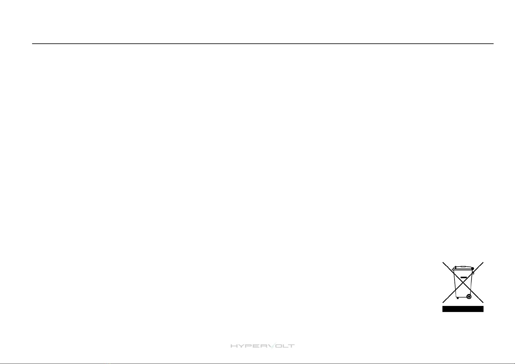
Disposal!"
Important information for the correct disposal of the product in accordance with Directive 2012/19/EC. At the end of its
useful life, the product should not be disposed of as urban waste. It must be taken to a collection centre for special and
differentiated disposal or to a distributor that provides this service.
Safety Notice

3
CT Connector
Block
CT Clamp
Charging Cable
Holster
Charging Cable (fitted)
Charging Unit
M4 Enclosure Screws
Getting to know your Hypervolt: Product Overview
What comes in the box ?
LED Status
Indicator
Outer Ring LED
Status
Indicator
Charging Cable
243mm
328mm
101mm
Charging Plug

4
Please read before starting your install!
-Hypervolt products must be installed by suitably qualified trained personnel only. !
-Above all else the Requirements for Electrical Installations as set out in BS7671 (as amended) must be followed
with special attention to section 722.!
-In addition to the above the guidance given in the “Code of Practice for Electric Vehicle Charging Equipment
Installation” (as amended) by the IET must also be followed.!
-If you are unsure about any part of the installation of a Hypervolt product you must obtain clarification from our
technical department before proceeding.!
-After installation and within 48hrs the unit must be registered as having been installed. This is done by scanning
the QR code on the side of the unit or online. This is to validate the warranty, failure to do so will void the
warranty. Installers should aim to do this before leaving site.
Installation: Getting Started
1. Incoming Supply Connections (up to 10mm²)
2. Tethered Cable Connections
3. Incoming Supply Cable (HyperConnect)
4. Tethered Cable with Plug
5. Top Mounting Holes
6. Bottom Mounting Holes
7. Fan Connection
8. CT Connection (Current Clamp)
9. RCD Connection
10. ALM Adjustment Dial
11. Derating DIP Switches
12. Raspberry Pi
13. LED Front Plate Connection
14. Cutout for Additional Cable Gland
15. CP Connection
16. RJ45 Hardwire Connection
17. Ethernet Port
18. RCD
Location of Important Components

5
Installation: Enclosure Parts
A
B
C
A- Back Box !B- LED Plate !C- Front Enclosure

6
Installation: Mounting
STEP 1
Use the cardboard drilling template supplied with your Hypervolt to mark out the mounting holes for the back box (B).!
Your Hypervolt unit and accompanying holster should be fixed between 0.5m and 1.5m above the ground. We recommend the holster position in the diagram is the
best place for it relative to the Hypervolt's position.!
Drill out all 4 fixing holes and fit the top 2 screws (5) leaving them 10mm out. For brick the recommended would be to use a 5.5mm SDS drill, Red plugs & 4x40mm
screws. Hang the Hypervolt on to the top two screws.!
Maximum height 1.5m
Minimum height 0.5m
Before removing the LED Plate (B) we recommend first mounting your Hypervolt charger.
Please note the following;
- The mounting site should be flat, away from extreme external influences and close enough to the EV to prevent the tethered cable causing a trip hazard. "
- There are many different fixings that can be used depending on the material being fixed to so please provide the ones most appropriate, no fixings are supplied."
- The unit comes with a cardboard mounting template however a metal version can be purchased."
- Pole Mounts are available for purchase should you opt to install your Hypervolt as a freestanding charger.

7
STEP 2
Insert the bottom 2 screws (6) then tighten all 4 up pinching the unit up tight to the wall.!
Make sure the unit sits level and adjust if required.!
Installation: Mounting (Continued)

8
Installation: Accessing the Connections
STEP 3
The Hypervolt has a removable LED plate which should be removed to access the connections and then replaced before the front enclosure (C) is fitted.!
To remove simply pull up on the top two tabs and unhook the plate. !
Separate the square white cable joint behind pressing down on the latch to release it. The unit will be shipped with this connector already disconnected however still
take care on first removal just in case.!
Put the LED Plate back in the box to keep it save until you refit it.!

10
Installation: Wiring and Connections
The Hypervolt requires two types of connections; one for supplying power and one for sending CT information (Load Management (ALM), Solar Input etc.)"
The CT connection can also be used for hardwiring internet if a primary Wi-Fi connection is not available or too weak, please refer to our website on this. Cat5 cable
should be used for the CT/Hardwire connection as it contains enough cores for all eventualities. Hypervolt can supply HyperConnect Cable which contains the power
& data cable (Cat5) all in one for a neater easier install. Cables should only come in via. the bottom gland positions. Position (14) can be drilled out and a gland fitted
to bring in a separate data cable and maintain separation. Separate data & power cables should not be run directly next to each other outside of the unit."
STEP 4
Connect the power cables to the incoming terminals (1) and tighten to 2Nm.
We recommend using ferrules on stranded cables. Pictured is HyperConnect
(3) cable available from us. Do not use powered screwdrivers to tighten
terminals."
Tighten the CTS Gand provided to hold the incoming cable in place. If you
are using an SWA cable then the CTS gland should be replaced for an SWA
Gland (Not Provided).!
STEP 5
Connect the Cat5 cable to the CT green plug (8), use the brown pair keeping the
White/Brown cable to the left and the Brown to the right. Remember to joint the
White/Brown to the White cable a the CT and the Brown to the Black.!
If you need hardwired internet use the remaining Orange and Green pairs
terminated in an RJ45 plug which can be inserted in the RJ45 socket (9). More
details of this are on our website.!
8
8
9
4
14
2
1

11
Installation: Power and CT Connection
STEP 6
There are two methods of connecting the Hypervolt to an electrical supply (Connection Method 1 or 2) which can be done using a further two methods of wiring (1
Wire Method or 2 Wire Method)."
Connection Method 1:
A separate consumer unit spurred into the existing meter tails is installed just for the use of the Hypervolt unit. HyperConnect (1 Wire Method Orange cable only) is run
from the Hypervolt unit and a joint made within the consumer unit to the CT Clamp Cable. If you are not using HyperConnect then run a separate supply cable and
separate Cat5 cable for the CT (2 wire method Orange & Black Cables) these cables must not be run directly alongside each other. "
Connection Method 2:
This is the same as above apart from the supply is taken from an existing consumer unit. Remember not to share an RCD with another circuit. Both wiring methods
can still be used."
For Both Methods
Connect the power cable to a suitably sized protective device. The Hypervolt takes a maximum load just below 32A. Consideration should be given to if a 32A or 40A
device is used based upon the operating environment. A 32A device may run too warm and trip out prematurely over a long charging period if it is between other
loaded devices. The Hypervolt must be on an individual (not supplying other circuits) A Type RCD double pole device. If an RCD is used an additional MCB (32A or
40A) will need to be included for overload protection. If an A Type RCBO (32A or 40A) is to be used please remember this must also be double pole."

12
Installation: Refitting the LED Plate
STEP 7
Once you have finished wiring in your Hypervolt charger, you will need to re-fit the LED plate (B). First reconnect the square white LED cable connector back together,
it should click. Put the top two tabs of part (B) over their locators on the top side of the back box (A). Now pull down on the middle bottom edge of part (B) and click
the bottom into place. Take care not to trap any cabling between parts A & B.

13
STEP 8
Lastly slide the front enclosure (C) onto the unit and secure using the four M4 screws supplied in the box. A small amount of pressure will be required on the front or
the front enclosure to line the holes up. Please take care not to cross thread the screws and certainly do not do these up using a powered tool such as an electric
screwdriver. Spare screws and captive square bolts are supplied if you lose or damage one. To change the captive bolts first pop out the green retaining peg."
Installation: Fitting the Front Enclosure

14
RCD (Residual Current Device)
An RCD is a safety device used to ensure that the charger stops supplying electricity in the event that there is an electrical fault to earth. !
The Hypervolt has built-in 6mA DC protection but no built-in AC protection, it must therefore be connected to an individual “A” Type Double Pole RCD
or RCBO not exceeding 30mA; complying with IEC61008-1 /IEC61009-1 / IEC60947-2 / IEC62423.
CT (Current Transformer) often called Current Clamp or CT Clamp
The single CT clamp supplied must be fitted to measure the main load on the property and discover solar export.!
The CT clamp provided should go around the main incoming Live (Brown or Red) meter tail with the arrow pointing in the normal direction of current
flow (Please refer to page 10 for further installation instructions). It is equally important that the wires from the CT clamp go the correct way round
inside the Hypervolt unit, the White Wire should go in the LEFT and the Black Wire should go in the RIGHT of the green connection plug (8). If you
extend the wires remember to follow these connections through. Details of how to test the CT clamp are on page 15.!
The CT Clamp should be positioned where it will measure the total load on the property. If you wish to position it in a different location due to
practicality permission should be sort from Hypervolt first. Be aware that positioning other than at the origin of the supply will limit the functionality of
the Hypervolt.!
Note: The CT clamp wiring can be extended up to 40m using Cat5e cable or 80m using HyperConnect cable.
PEN Fault Protection
Hypervolt chargers have built-in PEN fault protection which means they can be connected to a PME (TN-C-S) incoming service which shares Neutral &
Earth in the same conductor. There is no requirement to install an additional earth rod. In the event that the Protective Earth and Neutral (PEN)
conductor becomes damaged/disconnected our PEN Fault system will isolate all conductors to protect the user from potential danger a PEN fault
presents.
Overheating Sensing
Hypervolt chargers have built-in temperature sensors; in the event where it recognises there is too much heat being generated it will reduce the current
being delivered to the EV, this will ensure the charger is not damaged as a result of overheating.
Installation: Monitoring and Protection Devices

15
Installation: Automated Load Management
ALM (Automated Load Management) Testing
1. Isolate the supply to the Hypervolt & remove the cover.!
2. Locate the ALM setting dial (10) in the bottom left corner of the PCB
(Printed Circuit Board).!
3. Set the ALM dial to “2”. Take care to set the dial correctly, note that it
comes from the factory set to “0”.!
4. Replace the cover and turn the power back on.!
5. Plug the Hypervolt into your EV testing adaptor and set the adaptor to
"C" (Car Charging), the bolt on the front of the charger will go green.!
6. Turn on the customers kettle to increase house load to above 10A.!
7. Watch that the green bolt on the front of the Hypervolt decreases.!
8. Turn the kettle off and check the green bolt extends back.!
9. Isolate the supply to the Hypervolt & remove the cover.!
10. Set the ALM dial (10) back to the required load setting (60A is 6, 80A is 7
& 100A is 8). You might choose to set this to 60A even if the main fuse is
100A. !
11. Replace the cover and turn the power back on.!
ALM will not function if the CT clamp is not fitted.!
Top tip: It is a good idea to carry a basic amp measuring clamp meter with
you as part of your installer kit. This way you can measure the amperage
being drawn by the property to confirm it starts under 10A.!
11

16
Installation: Maximum Operating Current
Setting the Maximum Operating Current (Hard Set)
1. Isolate the supply to the Hypervolt & remove the cover.!
2. Locate the “Hard Set” dip switches (11) in the bottom left corner of the
PCB.!
3. The dip switches are factory set to the maximum 32A.!
4. Change the first two dip switches to your required maximum output as
per the following positions:!
!
5. Replace the cover and turn the power back on.!
Reducing the maximum operating current can sometimes be requested by
your DNO and should be done using the Hard Set method only not the soft
set.
It is possible to limit the maximum current the Hypervolt Charger will operate at by permanently derating the unit using the internal dip
switches. This is called a “Hard Set” as opposed to a “Soft Set” which can be done from the app.
11

17
Using your Charger: LED Statuses
Your smart EV charger helps to indicate what the charger is doing using the LED bolt on the front and the ring around the front enclosure.
Please note these colours will only show if your charger is set to the “No Effect” LED Mode."
Blue
Solid: Ready to use, no
car plugged in."
Pulsing: Plugged in
and waiting for car to
start charge "
If the Ring is Pulsing
White there is no
internet connection."
Purple
Solid: Set to scheduled
charge but no car
plugged in."
Pulsing: Car plugged in,
waiting to start charging
accordingly to set
schedule.
Green
Solid: Car is charging. "
Reduced bolt size
indicates lower charging
rate due to activation of
ALM safety system or
derating of charger."
Flashing: Waiting on
random delay (page 25)
Orange
Solid: Charger Locked"
Flashing: A Locked
charger is trying to be
used.
Red
The Charger’s safety
system has activated.
The unit is no longer
charging your car."
Check status in the
Hypervolt App and refer
to troubleshooting on
page 27.
Yellow
Solid: Charger inhibited
due to lack of solar
export (Super Eco
Mode Only)"
Pulsing: Insufficient
solar power to charge
vehicle or stopped
from app."

18
Installation: App Setup
We recommend installing the Hypervolt app, this enables you to control and monitor the charger. The app is free and can be downloaded
from either the Google Play Store (Android) or App Store (Apple). Follow the instructions below to get set up for the first time.
Create an Account
On the “Sign Up” page fill in your
email address and your own
unique password."
Google or Apple account users
can sign up using the icons above."
Adopt a Charger
When you first sign in there will be
no chargers adopted to your
account so click start to begin. "
You must be stood next to the
charger to complete the next
steps."
Select a Charger
Select the charger shown on
the list as “Available”. Units
already assigned to an
account will show as
“Unavailable”."
Sign In
Re enter your details each
time you need to sign in. Click
“Forgot my password” if you
cannot remember or you want
to change it."

19
Success!
Once the Wi-Fi network
has been connected the
LED ring around the
Hypervolt will change from
pulsing white to solid blue."
You now need to wait 5
minutes for the app to be
useable. Tick the box to
confirm you know to wait.
Installation: App Setup (continued)
Adoption Issues
It will take a few seconds to
get your charger adopted.
Don’t walk away from the
Hypervolt during this process.
If you get an “Error” screen
just move closer and click try
again.
Connect
Once the Hypervolt is
adopted the next screen
will display the Wi-Fi
networks available in your
area."
Choose the Wi-Fi network
you wish to connect your
Hypervolt to, type in the
password and hit “Connect. "
Its very important that the
signal strength is below
-70dBm for a reliable
connection.
Connection Issues
If the network is not
available or you have
typed in the password
wrong you will see this
screen. "
Just click continue to try
again.
Ready to Go
Now the app is connected
you can control any of the
functions from anywhere in
the world so long as your
phone has an internet
connection. "
To confirm all is good why
not try changing the LED
mode or brightness?
Other manuals for Home 2.0
2
Table of contents
Other HYPERVOLT Batteries Charger manuals