HYT TM-800 User manual

THANK YOU!
Thank you for your purchase of HYT mobile radio TM-800. We believe
this easy-to-use radio will provide you with dependable and reliable
communications at peak efficiency. Please read this manual carefully
before use. The information presented herein will help you to derive
maximum performance from your radio.
MODELS COVERED IN THIS MANUAL
TM-800 UHF Mobile Radio
TM-800 VHF Mobile Radio
TM800.p65 2005-6-29, 10:161

zDo not touch the metal surface of the radio while it is in use.
zDo not mount the radio such that the chassis can come in contact with skin.
zHigh temperatures may burn you skin.
CAUTION
1
TM800.p65 2005-6-29, 10:162

zVehicle installation: The antenna can be mounted at the
center of a vehicle metal roof or trunk lid if the minimum
safe distance is observed.
Antenna substitution: Don’t substitute any antenna for the
one supplied or recommended by the manufacturer or
radio dealer. You may be exposing person(s) to excessive
radio frequency radiation. You may contact your radio dealer
or the manufacturer for further instructions.
Warning
Maintain a separation distance from the antenna to
person(s) at least 60cm (24inches).
MANDATORY SAFETY INSTRUCTIONS
TO INSTALLERS AND USERS
zUse Only manufacturer or dealer supplied antennas.
zAntenna minimum safe distance: 60cm(24 inches).
zAntennas used for this transmitter must not exceed an
antenna gain of 0 dBd .
The FCC (Federal Communications Commission)
has adopted a safety standard for human
exposure to RF energy which is below the OSHA
(Occupational Safety and Health Act) limits.
zAntenna mounting: The antenna supplied by the manu-
facturer or radio dealer must not be mounted at a loca-
tion such that during radio transmission, any person
can come closer than the above indicated minimum safe
distance to the antenna (i.e. 60cm/24inches).
zTo comply with current FCC RF Exposure limitations, the
antenna must be installed at or exceeding the minimum
safe distance indicated above, and in accordance with
the requirements ot the antenna manufacturer or
supplier.
2
“ This transmitter is authorized to operate with a maximum
duty factor of 50%, in a typical push-to-talk mode, for
satisfying FCC RF exposure compliance requirements.”
TM800.p65 2005-6-29, 10:163

Contents
User Safety, Training, and General Information ----
----------------------------------------------------------------4
Compliance with RF Energy Exposure Standards -
----------------------------------------------------------------4
FCC Compliance --------------------------------------------- 5
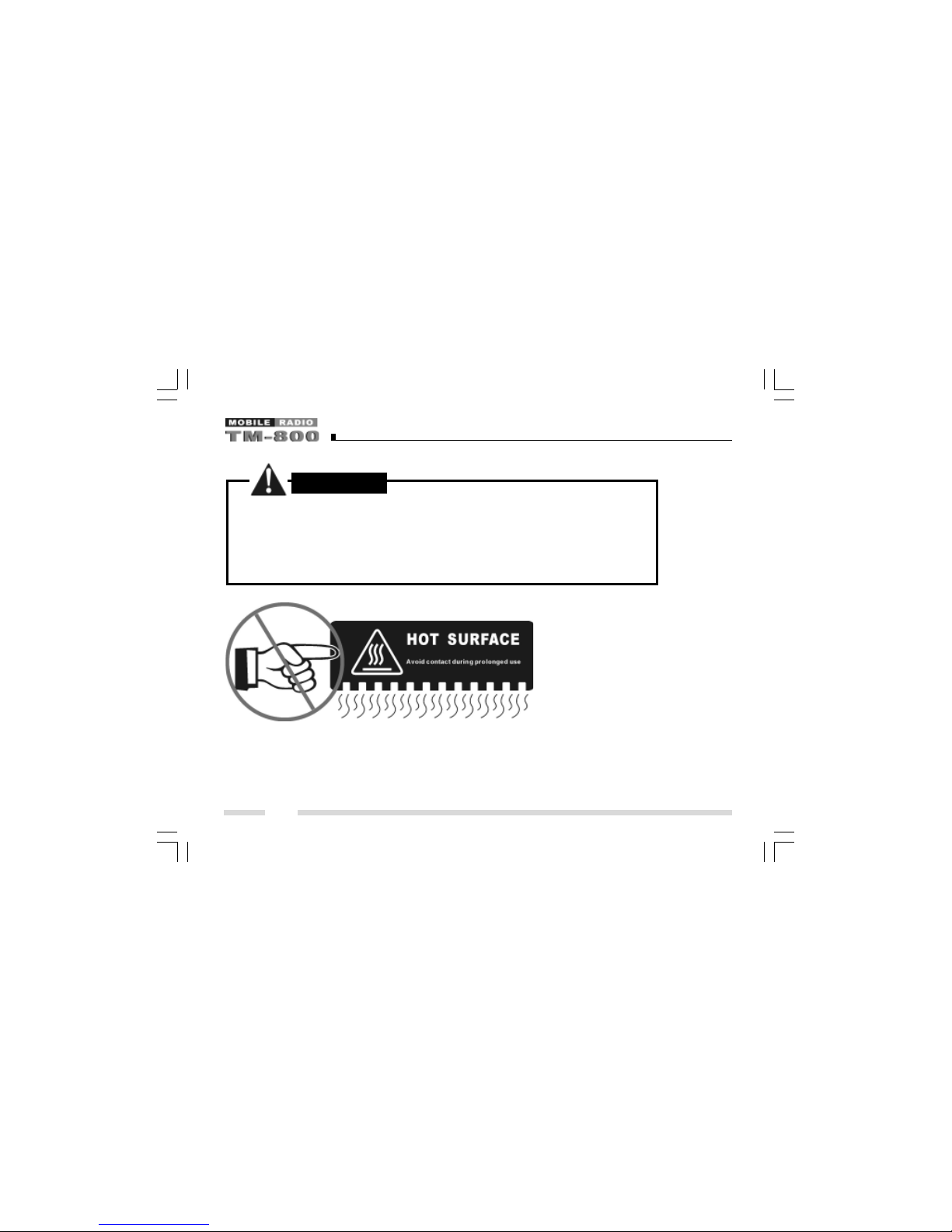
Precautions ----------------------------------------------------5
Product Inspection ------------------------------------------ 7
Radio Installation---------------------------------------------8
Radio Overview --------------------------------------------- 10
Basic Operations------------------------------------------- 14
Turn the Radio On/Off ------------------------------------- 14
Adjust the Volume ------------------------------------------ 14
Monitor --------------------------------------------------------- 14
Select a Channel -------------------------------------------- 15
Select a Zone ------------------------------------------------ 15
Receive-------------------------------------------------------- 15
Transmit ------------------------------------------------------- 16
Selectable Power Level----------------------------------- 16
Beginning / End of Transmission ID -------------------- 16
Channel Scan ------------------------------------------------ 17
Busy Channel Lockout (BCL) --------------------------- 19
BCL Override ------------------------------------------------ 19
DTMFCall ----------------------------------------------------- 20
Code Squelch ------------------------------------------------ 22
Auto Transpond--------------------------------------------- 23
Off-Hook Decode ------------------------------------------- 23
Time-Out-Timer (TOT) ------------------------------------- 23
Emergency Call ---------------------------------------------- 24
Stun & Revive------------------------------------------------ 24
Programmable Auxiliary Functions ----------------- 25
Reverse Frequency---------------------------------------- 25
Talkaround ---------------------------------------------------- 25
Selectable Squelch Level--------------------------------- 25
User Selectable Tone (UST) ----------------------------- 26
Public Address ---------------------------------------------- 26
Dual Home Channels --------------------------------------- 27
Horn Alert ----------------------------------------------------- 27
Selectable 2-Tone Encode ------------------------------- 27
Selectable 5-Tone Encode ------------------------------- 27
Display Frequency ----------------------------------------- 28
Display Label------------------------------------------------- 28
Display Mode------------------------------------------------- 28
LCD Backlight ------------------------------------------------ 28
Compander --------------------------------------------------- 28
Scrambler ----------------------------------------------------- 28
GPS Report --------------------------------------------------- 29
Short Message ---------------------------------------------- 29
Status Message--------------------------------------------- 29
Optional Signalling ------------------------------------------ 29
User Set Mode ---------------------------------------------- 31
Appendix 1 Entering Characters --------------------- 50
Optional Accessories ------------------------------------ 51
3
TM800.p65 2005-6-29, 10:164

User Safety, Training, and General
Information
READ THIS IMPORTANT INFORMATION ON SAFE AND
EFFICIENT OPERATION BEFORE USING YOUR HYT
MOBILE RADIO.
CompliancewithRFEnergyExposure
Standards
Your HYT mobile radio is designed and tested to comply with
a number of national and international standards and guide-
lines (listed below) regarding human exposure to radio fre-
quency electromagnetic energy. This radio complies with
the IEEE and ICNIRP exposure limits for occupational/con-
trolled RF exposure environment at operating duty factors of
up to 50% transmitting and is authorized by the FCC for
occupational use only. In terms of measuring RF energy for
compliance with the FCC exposure guidelines, your radio
radiates measurable RF energy only while it is transmitting
(during talking), not when it is receiving (listening) or in
standby mode.
Your HYT mobile radio complies with the following
of RF energy exposure standards and guidelines:
zUnited States Federal Communications Commission,
Code of Federal Regulations; 47CFR part 2 sub-part J
zAmerican National Standards Institute (ANSI)/Institute
of Electrical and Electronic Engineers (IEEE)
C95. 1-1992
zInstitute of Electrical and Electronic Engineers (IEEE)
C95. 1-1999 Edition
zInternational Commission on Non-Ionizing Radiation
Protection (ICNIRP) 1998
Operational Instructions and Training Guidelines
To ensure optimal performance and compliance with the
occupational/controlled environment RF energy exposure
limits in the above standards and guidelines, users should
transmit no more than 50% of the time and always adhere
to the following procedures:
Transmit and Receive
To transmit (talk), push the Push-To-Talk (PTT) button; to
receive, release the PTT button.
Approved Accessories
For a list of HYT approved accessories, see the accesso-
ries page of this user manual or visit the following website
which lists approved accessories:
http://www.hyt.com.cn http://www.hyt.cn
4
TM800.p65 2005-6-29, 10:165

FCC Compliance
Part 15 Compliance
This equipment has been tested and found to comply with
the limits for a Class B digital device, pursuant to part 15 of
the FCC Rules. These limits are designed to provide rea-
sonable protection against harmful interference in a resi-
dential installation. This equipment generates, uses and
can radiate radio frequency energy and, if not installed and
used in accordance with the instructions, may cause harm-
ful interference to radio communications. However, there
is no guarantee that interference will not occur in a particu-
lar installation. If this equipment does cause harmful inter-
ference to radio or television reception, which can be de-
termined by turning the equipment off and on, the user is
encouraged to try to correct the interference by one or
more of the following measures:
zReorient or relocate the receiving antenna.
zIncrease the separation between the equipment and
receiver.
zConnect the equipment into an outlet on a circuit differ-
ent from that to which the receiver is connected.
zConsult the dealer or an experienced radio/TV techni-
cian for help.
FCC Licensing Requirements
Your radio must be properly licensed Federal Communica-
tions Commission prior to use. Your HYT Wireless dealer
can assist you in meeting these requirements. Your dealer
will program each radio with your authorized frequencies,
signalling codes, etc., and will be there to meet your com-
munications needs as your system expands.
Precautions
General Safety Standards
zDo not attempt to configure the radio while driving; it is
too dangerous.
zDo not operate your radio when someone is either touch-
ing the antenna or standing within 2 or 3 feet of it, to
avoid the possibility of radio frequency burns or related
physical injury.
zDo not operate the radio near dynamite blasting caps or
in an explosive atmosphere.
zSwitch OFF the radio while refueling or parking at gas
station.
zTurn off your radio in any place where posted notices
instruct you to do so.
zDo not modify the radio for any reason.
5
TM800.p65 2005-6-29, 10:166

zDo not expose the radio to direct sunlight over a long
time, nor place it close to heating source.
zDo not place the radio in excessively dusty, humid areas,
nor on unstable surfaces.
zRefer service to qualified technicians only.
Operation Safety Guidelines
zFor vehicles equipped with electronic anti-skid braking
systems, electronic ignition systems or electronic fuel
injection systems, interferences may occur during the
radio transmission. If the foregoing electronic equip-
ments are installed on your vehicle, please contact your
dealer for further assistance to make sure that the ra-
dio transmission will not interfere with these equipments.
zFor radio installation in vehicles fueled by LP gas with
LP gas container within interior of the vehicles, the fol-
lowing precautions are recommended for personal
safety:
(1) Any space containing radio equipment shall be
isolated by a seal from the space in which the
LP gas container and its fittings are located.
(2) Remote (outside) fitting connections shall be
used.
(3) Good ventilation is required for the container
space.
Safety:It is important that the operator is aware of, and
understands, hazards common to the operation of any radio.
Installation Safety Guidelines
zDo not mount the mobile radio overhead or on a sidewall
unless you take special precautions.
zIf someone were to remove the radio and fail to replace
it properly, road shock could bump the radio loose, and
the falling radio could, in some circumstances, cause
serious injury to the driver or a passenger. In a crash,
even when properly installed, the radio could break
loose and become a dangerous projectile.
6
TM800.p65 2005-6-29, 10:167

Product Inspection
Please carefully unpack the radio. Before use, it is recom-
mended that you inspect the product as follows.
First check the shipping carton for any signs of damage.
Confirm the supplied product against the packing slip to
assure accuracy. If any items are missing or have been
damaged during shipment, please file a claim to the carrier
immediately.
Supplied Accessories
Item Quantity (pcs)
DC Power Cable 1
Mounting Bracket 1
Microphone 1
Microphone Hanger 1
Screw Set 6
Fuse 2
Owner’s Manual 1
Microphone SM07R2 Microphone Hanger
& Microphone cable
Mounting bracket adjustment screw
screw set Fuse
Power cable
7
TM800.p65 2005-6-29, 10:168

Radio Installation
Installing the Radio
1. Attach the mounting bracket, using the 4.8 x 20mm self-
tapping screws, in a location where convenient opera-
tion is accessible.
2. Connect the antenna and the supplied power cable to
the radio.
3. Slide the radio into the mounting bracket and secure it
using the Adjustment screws.
4. Mount the microphone hanger, using the 4 x 16mm self-
tapping screws, in a location where it will be within
easy reach of the user.
5. Connect the microphone plug to the microphone jack on
the front panel of the radio, then place the microphone
on the hanger.
Fig. 1 Radio Set Connection Detail
1. Microphone
2. Mounting bracket
3. 4.8 ¡Á20 mm Self-tapping screw
4. Microphone hanger
5. 4 ¡Á16 mm Self-tapping screw
6. Power input connector
7. Red lead
8. Black lead
9. Fuse
10.Antenna connector
11. Main unit
12.Adjustment screw
8
TM800.p65 2005-6-29, 10:169

Installation Tools
The following tools are required for proper installation of
your radio:
zElectric drill: ¡é6mm or above
zCross head Screwdriver
¡ö¡ö
¡ö¡ö
¡ö
Warnings:
1. The radio operates in 13.6 ¡À 5£¥V negative ground
systems only. Check the voltage and polarity of the
power supply on the vehicle before installation.
2. Be sure to check how far the screw will extend below
the radio surface to avoid damage to the auto wiring or
auto parts when drilling mounting holes.
3. Connect the radio with the supplied antenna and power
cable before installing the radio by the mounting bracket.
4. Install the radio securely using the supplied mounting
bracket to make sure that the radio will not loosen in the
event of accidents. The loose radio may cause injury to
the passenger.
Radio Installation
5. Arrange the installation location of the radio to make
sure that the control unit in the front panel is convenient
for operation.
6. Be sure to determine the location of the installing holes
before installation and drilling.
7. Be sure to make room at the rear of the radio for power
cable connection.
8. When replacing the fuse in the DC power cable, be
sure to replace it with a fuse of the same value. Never
replace a fuse with one that has a higher value.
9
TM800.p65 2005-6-29, 10:1610

Radio Overview
Front Panel View
1. Power Switch
Press to switch the radio on/off.
2. Selector Knob
Volume Up/Down, Channel Up/Down, Zone Up/Down
features can be programmed to this knob (set by your
dealer).
Turn the knob clockwise to adjust upwards and coun-
terclockwise to adjust downwards.
3. LCD Display
Please refer to “LCD Display” section.
4. Up/Down Key
Volume Up/Down, Channel Up/Down, Zone Up/Down
features can be programmed to the keys (set by your
dealer).
5. Indicator
6. Speaker
7. Programmable Function Key (PF1-PF6)
Your dealer can program these keys as shortcuts to
various radio features.
Please refer to “Programmable Function Key” section.
8. Microphone Jack
Insert the microphone plug into this jack.
LED Indicator
¡ö¡ö
¡ö¡ö
¡ö
The LED indicator
zglow red while transmitting .
zglow green while receiving .
zflash orange when receiving code squelch, selective
call, the matching 2-Tone/5-Tone or DTMF signaling.
10
TM800.p65 2005-6-29, 10:1611

LCD Display
Indicator Description
1. Display zone / channel number.
2. Display zone / channel label (set
by your dealer, up to 12 alphanu
meric characters).
3. Display channel Frequency
4. Display the preprogrammed func-
tions
1. Display zone / channel number.
2. Display transmit power level
(H, M or L).
3. Display the preprogrammed func-
tions
Radio Overview
Appears when the selected channel is
busy.
Appears when [MONI] key is pressed
to disable CTCSS, CDCSS, DTMF or
2-Tone/5-Tone.
Appears when [MONI] key is pressed
to switch the speaker on.
1. Indicate second development feature.
2. Appears when the auxiliary function
is activated.
SCAN Appears while scanning.
Appears when transmitting a selective
call.
Appears when a new message is
received.
Appears when the selected zone is in
the scan list.
Appears when the selected channel is
in the scan list.
11
A
CALL
TM800.p65 2005-6-29, 10:1612

Programmable Function Key
PF1-PF6 key can be programmed with the following auxil-
iary functions:
1. Off
2. VOL UP
3. VOL Down
4. CHUp
5. CH Down
6. Zone Up
7. Zone Down
8. MoniA
9. MoniB
10.MoniC
11. MoniD
12.DLabel
13.Dfreq
14.Dmode
15.UserTone
16.Sel2Tone
17.Sel5Tone
18.TXPower
19.Scan Add/Del
20.Reverse
21.TA
22.SELSQL
23.HomeCH
24.PA
25.HornAlert
26.LCDBL
27.Scramble
28.Compand
29.AUXA
30.AUX B
31.Send GPS
32.Emergency
33.Message
Radio Overview
12
TM800.p65 2005-6-29, 10:1613

Rear Panel View
1. Antenna Connector
Used to connect external antenna.
2. Power input Connector
Adopt HYT-authorized DC power cable and 13.6 V
input AC power.
3. Speaker Jack
Used to connect external speaker and only available
for the plug of 3.5 mm.
4. GPS Antenna Jack
5. 15 Pin Connector (for accessories)
Radio Overview
13
TM800.p65 2005-6-29, 10:1614

Turn the Radio On/Off
Press the Power switch to switch the radio on.
Press and hold the Power switch for approximately 1 sec-
ond to switch the radio off.
If Power on Password is set to protect your radio, “Chk P”
and the cursor will appear on the display when power is
turned on. You can unlock the radio by entering the correct
password (8 digits maximum):
1. Select a digit (0-9) by rotating the selector knob.
If you are using an optional microphone with a keypad,
you can also enter the password by pressing the ap-
propriate keypad keys.
2. Press the [PF3] / [PF4] key to move cursor forward and
backward.
This step can be skipped when using the keypad.
3. Repeat steps 1 and 2 to enter the entire password.
4. Press the [PF6] key or the [PTT] key to complete the
entry.
Basic Operations
Adjust the Volume
Selector Knob, [¡ø] / [¨‹
] or the function keys PF1-PF6 can
be programmed with VOL Up / VOL Down features to
adjust volume level.
Rotate the Selector Knob clockwise or press the key which
be programmed as [VOL Up] key to increase the volume;
rotate the knob counter-clockwise or press the key which
be programmed as [VOL Down] key to decrease the
volume. The current volume level is displayed on the LCD.
The LCD returns to original display mode in 5 seconds.
Press any key to exit from the volume level display mode.
Monitor
If monitor feature is set by your dealer, press the key pro-
grammed as [MONI] in receive mode to monitor activity on
your selected channel.
Your dealer can select one of the following four modes for
monitor feature:
14
TM800.p65 2005-6-29, 10:1615

Basic Operations
zz
zz
zMonitor Unmute-Momentary
Holddownthe[MONI]keytoopenCTCSS/CDCSS/DTMF/
2-Tone/5-Tone signalling squelch. Release to close the
signalling squelch.
zz
zz
zMonitor Unmute-Toggle
Press the [MONI] key to open CTCSS/CDCSS/DTMF/2-
Tone/5-Tone signalling squelch. Press again to close
the signalling squelch.
zz
zz
zCarrier Squelch-Momentary
Hold down the [MONI] key to open carrier squelch; Re-
lease to close the carrier squelch.
zz
zz
zCarrier Squelch-Toggle
Press the [MONI] key to open carrier squelch. Press
again to close the carrier squelch.
Select a Channel
Selector Knob, [¡ø] / [¨‹
] or the function keys PF1-PF6 can
be programmed with CH Up/ CH Down features to select a
channel. Transmit/Receive frequencies of the channel are
set by your dealer.
Rotate the Selector Knob clockwise or press the key which
be programmed as [CH Up] key to select a channel upwards;
Turn the knob counterclockwise or press the key which be
programmed as [CH Down] key to select downwards.
Select a Zone
Selector Knob, [¡ø] / [¨‹
] or the function keys PF1-PF6 can
be programmed with Zone Up/ Zone Down features to
select a zone. Transmit/Receive frequencies of the chan-
nel are set by your dealer.
Rotate the Selector Knob clockwise or press the key which
be programmed as [Zone Up] key to select a zone upwards;
Turn the knob counterclockwise or press the key which be
programmed as [Zone Down] key to select downwards.
Receive
If your dealer has programmed CTCSS/CDCSS/DTMF/
2-Tone/5-Tone signalling on the selected channel, you will
hear calls only when the matching code or tone is received;
otherwise, all calls on the same channel can be heard.
15
TM800.p65 2005-6-29, 10:1616

Transmit
1. Press the key programmed as [MONI] to make sure that
the selected channel is not in use.
2. Hold down the [PTT] key.
3. Dial a DTMF number using the microphone keypad.
Step 3 is not necessary all the time.
4. Speak into the microphone with normal voice. The LED
glows red during transmission.
5. Release the [PTT] key to receive.
6. When your conversation is finished, return the micro-
phone to its hanger.
Selectable Power Level
If transmit power (programmed by your dealer) is set to
“high” (or “middle”) on any given channel, press the key
programmed as [TX Power] to toggle the TX power among
high, middle and low. The current power level is indicated
by “H” /”M” / “L” icon on the LCD.
Since low power helps to conserve battery power and
reduce the risk of interfering with others, you are recom-
mended to select low power when communication quality
is guaranteed.
Basic Operations
Notes:
zz
zz
zPress the [TX Power] key while using a channel pro-
grammed with low power, an error tone will sound and
the transmit power will not change.
zz
zz
zWhen changing a channel from high/middle power to
low power, all other channels programmed with high/
middle power will change to low power accordingly.
Beginning/End of Transmission ID Signal
The radio can be programmed to send Beginning/End of
Transmission ID when accessing / releasing repeaters or
telephone systems. The ID signal includes DTMF and
5-Tone types. Two modes can be configured:
zz
zz
zPress the [PTT] key to send a Beginning of Transmis-
sion ID Signal; Release the [PTT] key to send an End of
Transmission ID Signal.
zz
zz
zPress [*] while holding down the [PTT] key to send a
Beginning of Transmission ID Signal; press [#] while
holding down the [PTT] key to send an End of Transmis-
sion ID Signal (for DTMF type only).
16
TM800.p65 2005-6-29, 10:1617

Channel Scan
¡ö¡ö
¡ö¡ö
¡öScan Types
zz
zz
zSingle Zone Scan
All channels in the current zone that have been added
to the scan list can be scanned.
zz
zz
zMulti Zone Scan
All channels within all the zones that have been added
to the scan list can be scanned.
zz
zz
zList Zone Scan
The radio only scans the channels within the specified
range of zones that have been added to the scan list.
Individually each zone is assigned with a scan list, which
provides quick recognition of the zones to be locked out
of scan list.
Note: Scan list for each zone can be added/ deleted.
¡ö¡ö
¡ö¡ö
¡ö Scan Start
Press the key programmed as [SCN], scan starts from the
current channel and ascends through the channel num-
bers in scan list. “SCAN” appears on the LCD
Basic Operations
(“-SCAN X - ” in List zone scan mode, “X” is the current list
number).
Note: Scan function can be used only when two or more
channels are in the scan list.
¡ö¡ö
¡ö¡ö
¡ö Scan Stop
1. Press the [SCN] key again to stop scanning. “SCAN”
disappears on the LCD.
2. Activate the Monitor function.
3. Carrier is detected on channels where no signalling is
set.
4. Carrier is detected on channels where signalling is set,
and the matching signalling is received.
¡ö¡ö
¡ö¡ö
¡ö Scan Restart
When the radio stops on a busy channel, scanning can be
restarted according to the restart mode, which can be
programmed by the dealer as carrier-operated scan or
time-operated scan.
17
TM800.p65 2005-6-29, 10:1618

zz
zz
zCarrier Operated Scan
Scanning remains on an active channel until there are
no activities; while the channel is free, the radio re-
mains on the channel for the programmed Dropout De-
lay Time (programmed by your dealer) before it resumes
scanning.
zz
zz
zTime Operated Scan
Scanning remains on the active channel for only the
programmed Dropout Delay Time (programmed by your
dealer) before it resumes scanning. After the expiration
of Dropout Delay Time, the radio will begin scanning
other channels even if the channel is still busy.
¡ö¡ö
¡ö¡ö
¡ö
Dual Priority Scan
If your dealer has programmed dual priority channels, the
radio will periodically detect the activity on priority chan-
nels while stopping on non-priority channels. When any
activity is detected on the priority channels, the radio will
switch to the priority channels for communications.
“P1” appears on the LCD when the channel is set as
Priority 1, “P2” appears when set as Priority2, and “PP”
when set as both Priority 1 and Priority 2.
Basic Operations
¡ö¡ö
¡ö¡ö
¡ö Operator Selectable Priority Channel
If priority channel is programmed by your dealer as “Op-
erator Selectable”, you can set the current channel as
priority or non-priority channel:
Press the key programmed as [MONI] twice while holding
down the key programmed as [SCN], the current channel is
changed to “Priority 2”.
Press the [MONI] key three times while holding down the
[SCN] key, the current channel is changed to “Priority 1”.
Press the [MONI] key four times while holding down the
[SCN] key, the current channel restores to original setting.
¡ö¡ö
¡ö¡ö
¡ö Scan Add/Delete
This feature allows you to add/delete a channel to/from the
scan list in the non-scan mode.
1. Select the channels to be added/ deleted by using the
channel selector knob.
2. Press the key programmed as [Add/Del] to toggle be-
tween ADD and DELETE. “ ”appears on the LCD
when a channel is added.
Note: The radio only scans the channels that have been
added to the scan list.
18
TM800.p65 2005-6-29, 10:1619

¡ö¡ö
¡ö¡ö
¡ö
Look Back Temporary Disable
When scanning looks back and stops on a priority channel,
press the key programmed as [Add/Del] to deactivate the
Look Back function.
¡ö¡ö
¡ö¡ö
¡ö Nuisance Channel Temporary Delete
This feature allows you to temporarily add/delete a chan-
nel to/from the scan list during scanning.
When scanning stops on an undesired channel (e.g. nui-
sance channel), press the key programmed as [Add/Del],
the channel is temporarily removed from the scan list and
scanning resumes.
Note: The addition/ deletion of channels are not saved
when radio exits from the scan mode.
¡ö¡ö
¡ö¡ö
¡ö
Revert Channel
Press the [PTT] key during scanning, the radio will stop
scanning and switch to the preset revert channel
(programmed by your dealer) for transmission.
Basic Operations
¡ö¡ö
¡ö¡ö
¡öOff Hook Scan
Normally scanning is not controlled by microphone hook
status, it also means that the radio always scans, and
stops by signal presence. But if your dealer has programmed
Off Hook Scan feature, microphone must be on hook for
scanning.
Busy Channel Lockout (BCL)
When activated by your dealer, the BCL feature will pre-
vent you from talking on a channel that is already in use.
Press the [PTT] key while the channel is in use, the radio
will emit an alert tone and transmission will be inhibited.
Release the [PTT] key to stop the alert tone. Wait until the
channel is not in use before you try to transmit again.
BCL Override
If BCL Override feature is activated, you can override the
BCL feature and transmit on a busy channel. To override
the BCL, release the [PTT] key when the alert tone sounds,
then press the [PTT] key again within 0.5 second.
19
TM800.p65 2005-6-29, 10:1620
Other manuals for TM-800
4
Table of contents
Other HYT Radio manuals