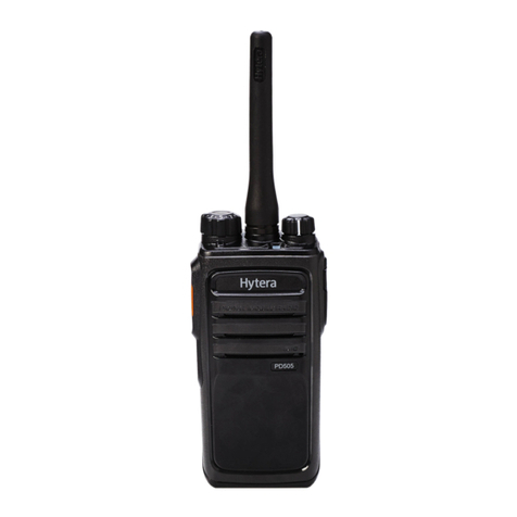
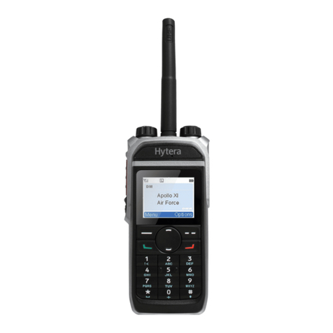
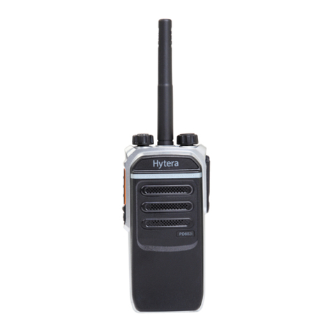
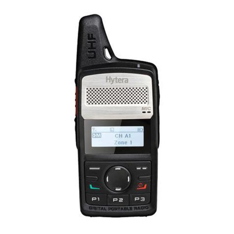
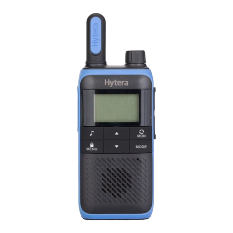
Hytera PD405 User manual

PD405
Digital Portable Radio
SERVICE MANUAL


Preface
This manual describes the information related to the product repair. It is intended for use by qualified
technicians only. To repair the product properly, please read this manual carefully before repairing.
This manual is applicable to the following product:
PD40X Digital Portable Radio (X may represent 2, 5, 6 or 8)

Copyright Information
Hytera is the trademark or registered trademark of Hytera Communications Corporation Limited (the
Company) in PRC and/or other countries or areas. The Company retains the ownership of its trademarks
and product names. All other trademarks and/or product names that may be used in this manual are
properties of their respective owners.
The product described in this manual may include the Company’s computer programs stored in memory
or other media. Laws in PRC and/or other countries or areas protect the exclusive rights of the Company
with respect to its computer programs. The purchase of this product shall not be deemed to grant, either
directly or by implication, any rights to the purchaser regarding the Company’s computer programs. Any
of the Company’s computer programs may not be copied, modified, distributed, decompiled, or
reverse-engineered in any manner without the prior written consent of the Company.
The AMBE+2TM voice coding technology embodied in this product is protected by intellectual property
rights including patent rights, copyrights and trade secrets of Digital Voice Systems, Inc. This voice
coding technology is licensed solely for use within this product. The user of this technology is explicitly
prohibited from attempting to decompile, reverse engineer, or disassemble the Object Code or in any
other way convert the Object Code into a human-readable format.
U.S. Patent No: #6,912,495 B2, #6,199,037 B1, #5,870,405, #5,826,222, #5,754,974, #5,701,390,
#5,715,365, #5,649,050, #5,630,011, #5,581,656, #5,517,511, #5,491,772, #5,247,579, #5,226,084 and
#5,195,166.
Disclaimer
The Company endeavors to achieve the accuracy and completeness of this manual, but no warranty of
accuracy or reliability is given. All the specifications and designs are subject to change without notice
due to continuous technology development. No part of this manual may be copied, modified, translated,
or distributed in any manner without the express written permission of us.
We do not guarantee, for any particular purpose, the accuracy, validity, timeliness, legitimacy or
completeness of the Third Party products and contents involved in this manual.
If you have any suggestions or would like to learn more details, please visit our website at:
http://www.hytera.com.

Documentation Information
Conventions
Icon Conventions
Icon Description
Tip Indicates information that can help you make better use of your product.

Note Indicates references that can further describe the related topics.
Caution Indicates situations that could cause data loss or equipment damage.
Warning Indicates situations that could cause minor personal injury.
DangerIndicates situations that could cause major personal injury or even death.
Notation Conventions
Notation Description
“ ”
The quotation marks enclose the name of a software interface element. For
example, click “OK”.
Bold
The text in boldface denotes the name of a hardware button. For example, press the
PTT key.
->
The symbol directs you to access a multi-level menu. For example, to select “New”
from the “File” menu, we will describe it as follows: “File -> New”.
Revision History
Version Release Date Description
V00 09-2015
Initial Release. This manual includes the following
frequencies:
VHF(136–174MHz)
UHF(400–470MHz)

VHF(136‐174 MHz)

VHF(136‐174 MHz)
Contents
i
Contents
1. Product Controls .................................................................................................................................. 1
2. Disassembly and Assembly................................................................................................................ 2
3. Exploded View and Packing Guide .................................................................................................... 4
3.1 Exploded View.................................................................................................................................. 4
3.2 Packing Guide .................................................................................................................................. 6
4. Specifications ....................................................................................................................................... 7
5. Circuit Descriptions ............................................................................................................................. 9
5.1 Baseband Section............................................................................................................................. 9
5.1.1 Power Supply Module ............................................................................................................ 9
5.1.2 Control Module ..................................................................................................................... 10
5.1.3 Audio Module.........................................................................................................................11
5.2 RF Section ...................................................................................................................................... 12
5.2.1 Transmitter Circuit ................................................................................................................ 12
5.2.2 Receiver Circuit .................................................................................................................... 14
5.2.3 Frequency Generation Unit (FGU)....................................................................................... 15
6. Troubleshooting Flow Chart ............................................................................................................. 17
6.1 Control Circuit ................................................................................................................................. 17
6.2 Receiver Circuit .............................................................................................................................. 18
6.3 Transmitter Circuit .......................................................................................................................... 20
6.4 FGU Circuit ..................................................................................................................................... 22
7. Interface Definition............................................................................................................................. 24
8. Tuning Description............................................................................................................................. 25
8.1 Required Test Instruments ............................................................................................................. 25
8.2 Tuning Procedures ......................................................................................................................... 25
8.2.1 Tuning the Radio .................................................................................................................. 25
8.2.2 Testing the Radio.................................................................................................................. 28
9. PCB View............................................................................................................................................. 30
10. Block Diagram .................................................................................................................................. 32
10.1 Overall Diagram of Radio ............................................................................................................. 32
10.2 Block Diagram of Power Supply Circuit ....................................................................................... 33
10.3 Block Diagram of Baseband Circuit.............................................................................................. 34
10.4 Block Diagram of Transmitter Circuit............................................................................................ 35
10.5 Block Diagram of Receiver Circuit................................................................................................ 36
10.6 Block Diagram of FGU Circuit ...................................................................................................... 37
11. Schematic Diagram.......................................................................................................................... 38
12. Parts List ........................................................................................................................................... 48

VHF(136‐174 MHz)
Product Controls
1
1. Product Controls
No.
Part Name
No.
Part Name
○
1 PTT (Push-to-Talk) Key ○
8 Accessory Connector
○
2 SK1 (Side Key 1) ○
9 Microphone
○
3 SK2 (Side Key 2) ○
10 Battery Latch
○
4 Channel Selector Knob ○
11 Antenna
○
5 Speaker ○
12 Belt Clip
○
6 LED Indicator ○
13 Battery
○
7 Power On-Off/Volume Control Knob / /

Disassembly and Assembly
VHF(136‐174 MHz)
2
2. Disassembly and Assembly
This section is designed to introduce the way to disassemble the radio. To assemble the radio, do vice
versa.
Caution
Position the waterproof ring into the radio properly during reassembly.
After reassembling, check the waterproof performance of the radio using the specific waterproof
test instrument of the Company.
Step 1 Remove the battery.
Step 2 Remove the antenna, Channel Selector knob and Power On-Off/Volume Control knob.
Step 3 Remove the nuts from the antenna connector, Channel Selector knob and Power
On-Off/Volume Control knob.

VHF(136‐174 MHz)
Disassembly and Assembly
3
Step 4 Remove the two screws on the aluminum chassis.
Step 5 Remove the aluminum chassis and the main board.
Step 6 Remove the eight screws on the main board.
Step 7 Unsolder the soldering joint of the antenna connector and remove the main board.

Exploded View and Packing Guide
VHF(136‐174 MHz)
4
3. Exploded View and Packing Guide
3.1 Exploded View
Parts list:
Note
For parts that are not marked with Part Number, their Part Numbers may vary with the frequency
band.
No.
Part No.
Description
Qty.
No.
Part No.
Description
Qty.
1 6002337000000
Bracket for PTT Key
Cover 1
24 8600000000100
Blank Label for
Aluminum
Chassis
1
2 6002336000000
PTT Key Cover 1
25 7400404000000 Waterproof Film 1
3 6100110700000
PTT Key (Silicone
Rubber)
1
26 86PD780400110 Warning Label 1
4 6002425000000
Front Case 1
27 8600000909500
Instructional Label
of RF
Transmission
1
5 6002338000000
Transparent Light
Guide
1
28 8600000906300 Anti-tamper Label 2
6 7400731000000
Speaker Felt 1
29 7102506002100 Machine Screw 2

VHF(136‐174 MHz)
Exploded View and Packing Guide
5
No.
Part No.
Description
Qty.
No.
Part No.
Description
Qty.
M2.5*6.0 mm
7 5001210000720
Speaker 1
30 6100527100000
Waterproof Ring
for Screw
2
8 7400244000000
Speaker Pad 1
31 6101228000000
Main Waterproof
Ring
1
9 6202121000000
Speaker Fixing Sheet 1
32 6300269000000
Aluminum
Chassis
1
10 7101904020200
Self-tapping Screw
ST1.9*4.0 mm 9
33 6101037000000
Waterproof Ring
for Battery
Connector
1
11 4399030000050
Gray Code Rotary
Switch
1
34 7500875000000
Protective Foam
of Filter
1
12 6001068000010
Channel Selector Knob 1
35 4400100036000
SMA RF
Connector
1
13 6100335000000
Antenna Waterproof
Ring
1
36 5205005000030
3.50 mm Earpiece
Connector
1
14 7209002501000
Antenna Nut 1
37 5205004000030
2.50 mm Earpiece
Connector
1
15 7102504000300
Machine Screw
M2.5*4.0 mm
2
38 1300D500U0020 Main Board 1
16 6001069000010
Volume Control Knob 1
39 5002220000070 Microphone 1
17 6201739000000
Knob Inner Lining 2
40 6100345000000 MIC Cover 1
18 7206002500210
Volume Switch Nut 2
41 6001978000000
Accessory
Connector Cover
1
19 6100334000000
O-RING of Knob
Switch
2
42 86TD500700200 Side Label 1
20 4323020000100
Volume Switch 1
43 7400329000000 MIC Pad 1
21 7500272000000
Heat Sink Pad 1
44 7400530000000
Waterproof MIC
Mesh
1
22 6002426000000
Rear Cover 1
45 86TD500700200 Logo Label 1
23 7103000075000
Machine Screw
M3.0*7.5 mm
2
46 86TD500700000 Model Label 1

Exploded View and Packing Guide
VHF(136‐174 MHz)
6
3.2 Packing Guide

VHF(136‐174 MHz)
Specifications
7
4. Specifications
General
Frequency Range 136‐174 MHz
Channel Capacity 256
Channel Spacing 25 kHz/12.5 kHz
Operating Voltage 7.4 V (rated)
Battery 1500 mAh Li-Ion battery
Battery Life (5-5-90 Duty Cycle, High TX Power)
High-capacity 1800 mAh Li-Ion Battery
Analog: about 12 h
Digital: about 16 h
Operating Temperature -30oC to +60oC
Dimensions (H*W*D)
(with standard battery, without antenna)
112 mm * 54 mm * 28 mm
Weight (with antenna and standard battery) About 270 g
Frequency Stability ±0.5 ppm
Receiver
Sensitivity
Analog
0.22 μV (12 dB SINAD)
0.22 μV (Typical) (12 dB SINAD)
0.4 μV (20 dB SINAD)
Digital 0.22 μV/BER 5%
Rated Audio Power Output 0.5 W (16 Ω load)
Rated Audio Distortion ≤3%

Specifications
VHF(136‐174 MHz)
8
Transmitter
Power Output 5 W/1 W
Spurious Emission
-36 dBm<1 GHz
-30 dBm>1 GHz
Modulation Limiting
±2.5 kHz @ 12.5 kHz
±5.0 kHz @ 25 kHz
FM Noise
40 dB @ 12.5 kHz
45 dB @ 25 kHz
Audio Distortion ≤3%
Note
All Specifications are tested according to applicable standards, and subject to changes without notice
due to continuous development.

VHF(136‐174 MHz)
Circuit Descriptions
9
5. Circuit Descriptions
5.1 Baseband Section
5.1.1 Power Supply Module
Diagram of Power Control
The power supply employs a single cell 7.4 V Li-ion battery. The RF section uses LDO to generate a 5 V
voltage for FGU and PLL circuits, as well as the control parts of TX circuits. The baseband section uses
LDO to generate a 3.3 V voltage for Codec, MCU and SCT3928. The core power supply of SCT3928
uses DC/DC to convert the voltage to 1.2 V.
To VCO
NTA7002N
PWR_ON
POWER_ON
7.4V
V_BAT SW-
LDO
XC6204F502PR
LDO
XC6204F502PR
DC-DC
ADP2370ACPZ-R7
DC-DC
ADP2370ACPZ-R7
To PLL
5VFGU
To TX
5VRT
POW-KEY-DET
3V6D
LDO
RP102N331B
LDO
RP102N331B
LDO
RP102N331B
LDO
RP102N331B
1V2D
3V3A
3V3D
3V3A_RX
3V3_FGU
LDO
RP102N331B
3V3D1
To Sicomm core
CODEC
MIC
MCU
E2PROM
LED
SW_channel
KEY
RX
PLL
Sicomm
Security Key
12.288MHz
CODEC
3V3D
PWR_CTRL_SI
RST

10
5.1.2 Control Module
The radio employs the STM32F101VET6(MCU)+SCT3928(Baseband IC) control solution.
STM32F101VET6 is the main controller unit (MCU), while SCT3928 is the baseband processor chip,
which is used for analog and digital modulation/demodulation, as well as digital voice encoding/decoding.
MCU communicates with SCT3928 via HPI BUS and connects to 512K EEPROM via I2C BUS.
STM32F101VET6 uses the frequency generated by 12 MHz crystal oscillator as the clock signal while
SCT3928 uses the frequency generated by 12.288 MHz crystal oscillator as the clock signal.
CODEC
TLV320AIC3204
STM32F101VET6
AMP
TDA2822D
MCLK
BCLK
WCLK
DIN
DOUT
MCLK
VDD3V3
12.288MHZ
SCL
SDA
Security Key
I2S
HPI[0..7]
VOICE
CODER
Protoccol
Stack 4FSK
FM
Demod
Channel
Selection
SCT3928
S0CLK
S0FS
S0DO
S0DI
S1CLK
S1FS
S1DO
S1DI
CLKIN
SCL
SDA
FLASH_CLK
FLASH_CE
FLASH_DI
FLASH_DO
MCU
PLL_CLK
PLL_CS
PLL_DATA
PLL_LD
MOD_VCO
MOD_REF
7.4VDC
DC-DC 3.6V
ADP2370ACPZ-R7
Fuse
3.6V
AF_IN
BEEP
3V3A
BAT
SW_channel
PTT
12MHZ
RESET 3V3D
EEPROM
I2C
3V3D
3V3D1 1V2
LOR
LOL
IN1R
IN1L
HPL
IN2L
serial port
VOX
VOX
EXT_interface
POWER SW
HCSN
HWRN
HRDN
RSTN
HOBIB
INTO
NMI
SK1
SK2
LED
POW_KEY_DET
TEM_LEV_DET_TC
PWR_CTRL_SI
FL_Fastlock_Ctrl
Pre_Fastlock_Ctrl
VCO_H_En
VCO_L_En
TV1\APC
BEEP1
TX_EN
RX_EN
RSSI
N_CON
SPK_EN
UART/USB
VOL
SW-
BATT_DEC
V_BAT
SW-
DC-DC 1.2V
ADP2370ACPZ-R7 1.2V
RP102N331B 3V3A
RP102N331B 3V3D
RP102N331B 3V3A_RX
RP102N331B 3V3_FGU
RP102N331B 3V3D1
XC6204F502PR
XC6204F502PR
5VFGU
5VRT
PWR_CTRL_SI
3V3D
Reset signal
Circuit Descriptions 9HF (‐ MHz)

VHF(136‐174 MHz)
Circuit Descriptions
11
5.1.3 Audio Module
Audio Diagram
The audio processing section uses SCT3928 and TLV320AIC3204. The audio amplifier uses TDA2822D.
The diagram is as follows:
CODEC
TLV320AIC3204
AMP
TDA2822D
MCLK
BCLK
WCLK
DIN
DOUT
MCLK
VDD3V3
12.288MHZ
SCL
SDA
Security Key
I2S
VOICE
CODER
Protoccol
Stack 4FSK
FM
Demod
Channel
Selection
SCT3928
S0CLK
S0FS
S0DO
S0DI
S1CLK
S1FS
S1DO
S1DI
CLKIN
SCL
SDA
FLASH_CLK
FLASH_CE
FLASH_DI
FLASH_DO
MOD_VCO
MOD_REF
AFDET
BEEP
3V0A
BAT
3V0D 1V2
LOR
LOL/R
IN3R
IN1L
HPL/R
IN2L
AF_MUTE
VOX
These two signals go to FGU for
modulation
This signal is down converted by
RX end and output by BA4116
RX path
The signal demodulated by RF module is sent to the input port of the third path of TLV320AIC3204
for internal amplifying. After AD conversion, the signal is sent to SCT3928 via I2S interface for
internal processing. Then the signal is sent to TLV320AIC3204 via I2S interface for DA conversion
and internal amplifying. Finally, the audio signal is output from the HPL/R port of TLV320AIC3204 to
audio power amplifier TDA2822D for amplifying, so as to drive the speaker.
TX path
The audio signal received by the MIC is divided into two paths: one path is processed and sent to
MCU for VOX sampling; the other path is sent to TLV320AIC3204 for AGC amplifying. After AD
conversion, the latter path of signal is sent to SCT3928 via I2S interface for internal processing. Then
it is sent to TLV320AIC3204 via I2S interface for DA conversion and amplifying. Finally, the audio
signal is output to FGU for two-path modulation via the LOL/R port of TLV320AIC3204.
Audio Power Amplifier
Main parameters of TDA2822Dare listed in the table below:
Rated Power (Po) 0.5 W R L =16 Ω
Maximum Power (Pmax) 1.6 W R L =16 Ω

Circuit Descriptions 9HF(‐ MHz)
12
5.2 RF Section
5.2.1 Transmitter Circuit
The transmitter circuit is mainly composed of:
RF Power Amplifier Circuit
Low-pass Filter Circuit (for suppressing harmonics)
Auto Power Control (APC) Circuit
Sampling Resistor
RF Power Amplifier Circuit
The carrier signal (TX signal) generated by TX voltage controlled oscillator (VCO) is modulated and
amplified via the buffer amplifier first, then passes through a pre-driver amplifier for primary power
amplification. After that, the signal goes to the driver amplifier (RD01) for further power amplification,
then the driver amplifier provides properly amplified signal to the final-stage amplifier (RD07) for final
power amplification. After amplified by multiple amplifiers, the TX signal will pass through a microstrip
matcher at the output end of final-stage amplifier to complete output impedance matching, so as to
reduce output power loss due to impedance mismatch. Then the TX signal will go to the low-pass filter
through TX/RX switch circuit.
Low-pass Filter Circuit (for suppressing harmonics)
The low-pass filter for suppressing harmonics is a high-order filter composed of lumped-parameter
inductors and capacitors. Via this filter, the spurious signal within the stop band can be attenuated as
much as possible while the in-band ripple is within the required range.
APC Circuit
In the APC circuit, the drain current from the driver amplifier and final-stage amplifier is converted to a

VHF(136‐174 MHz)
Circuit Descriptions
13
voltage via the sampling resistor and subtracter circuit (composed of the first operational amplifier).
This voltage is compared with that of the APC circuit (output by DAC) at the second operational amplifier.
Then the error voltage, which is output by the second operational amplifier, controls TX power by
controlling the compensated gate bias voltage of the amplifiers (including the driver amplifier and the
final-stage amplifier).
Other manuals for PD405
1
Table of contents
Other Hytera Portable Radio manuals

Hytera
Hytera TC-508U1 User manual

Hytera
Hytera PD78X Series User guide

Hytera
Hytera PD982 User manual

Hytera
Hytera TC-780 User manual

Hytera
Hytera PD782i User manual

Hytera
Hytera PD78X Series User manual

Hytera
Hytera BD55X User manual

Hytera
Hytera PD56Xi User manual

Hytera
Hytera PD70X Series User manual

Hytera
Hytera PD985i User manual

Hytera
Hytera BD51XU1 User manual

Hytera
Hytera TC-508V User manual

Hytera
Hytera PD362i User manual

Hytera
Hytera PD482i User manual

Hytera
Hytera PD502 User manual

Hytera
Hytera PD46X User manual

Hytera
Hytera PD98X User manual

Hytera
Hytera BD505 User manual

Hytera
Hytera HP782 User manual

Hytera
Hytera HP60X User manual