Hytera DS-9300 User manual

User Manual

Copyright Information
Hytera is the trademark or registered trademark of Hytera Communications Corporation Limited (the
Company) in PRC and/or other countries or areas. The Company retains the ownership of its trademarks
and product names. All other trademarks and/or product names that may be used in this manual are
properties of their respective owners.
The product described in this manual may include the Company’s computer programs stored in memory or
other media. Laws in PRC and/or other countries or areas protect the exclusive rights of the Company with
respect to its computer programs. The purchase of this product shall not be deemed to grant, either directly
or by implication, any rights to the purchaser regarding the Company’s computer programs. Any of the
Company’s computer programs may not be copied, modified, distributed, decompiled, or
reverse-engineered in any manner without the prior written consent of the Company.
Disclaimer
The Company endeavors to achieve the accuracy and completeness of this manual, but no warranty of
accuracy or reliability is given. All the specifications and designs are subject to change without notice due
to continuous technology development. No part of this manual may be copied, modified, translated, or
distributed in any manner without the express written permission of us.
We do not guarantee, for any particular purpose, the accuracy, validity, timeliness, legitimacy or
completeness of the Third Party products and contents involved in this manual.
If you have any suggestions or would like to learn more details, please visit our website at:
http://www.hytera.com.

Antenna gain must not exceed 9dBi.
always adhere to the following procedures:
users should
This is A 90.219 CLASS A DEVICE.
Unauthorized use may result in significant forfeiture penalties,
You MUST register Class B signal boosters (as defined in 47 CFR 90.219) online at
This device must accept any interference rece
WARNING:
must be at least 0.65 meters away from human body.
FCC Statement
This equipment has been tested and found to comply with the limits for a Class B digital device, pursuant
to part 15 of FCC Rules. These limits are designed to provide reasonable protection against harmful
interference in a residential installation. This equipment generates and can radiate radio frequency
energy. If not installed and used in accordance with the instructions, it may cause harmful interference to
radio communications. However, there is no guarantee that interference will not occur in a particular
installation. Verification of harmful interference by this equipment to radio or television reception can be
determined by turning it off and then on. The user is encouraged to try to correct the interference by one
or more of the following measures:
Reorient or relocate the receiving antenna. Increase the separation between the equipment and
receiver.
Connect the equipment into an outlet on a different circuit to that of the receiver's outlet.
Consult the dealer or an experienced radio/TV technician for help.
Operation is subject to the following two conditions:
This device may not cause harmful interference.
ived, including interference that may cause undesired
operation.
Note: Changes or modifications to this unit not expressly approved by the party responsible for
compliance could void the user's authority to operate the equipment.
Operational Instructions and Training Guidelines
To ensure optimal performance and compliance with
exposure limits in the above standards and guidelines,
The antenna must be installed complying with the requirements of manufacturer or supplier, and it
This is NOT a CONSUMER device. It is designed for installation by FCC LICENSEES and QUALIFIED INSTALLERS.
You MUST have an FCC LICENSE or express consent of an FCC Licensee to operate this device.
www.fcc.gov/signal-boosters/registration.
including penalties in excess of $100,000 for each continuing violation.”
the general/Uncontrolled environment RF energy

d operations in an
de 65cm de dist
stance 65cm between the
Institute of Electrical and Electronic Engineers (IEEE) C95.1:2005 Edition
ISEDC Statement
This device complies with Innovation, Science and Economic Development Canada Compliance
license-exempt RSS standard(s). Operation is subject to the following two conditions:
This device may not cause harmful interference.
This device must accept any interference received, including interference that may cause undesired
operation.
Le présent appareil est conforme aux CNR d'Industrie Canada applicables aux appareils radio exempts
de licence. L'exploitation est autorisée aux deux conditions suivantes: (1) l'appareil ne doit pas produire
de brouillage, et (2) l'utilisateur de l'appareil doit accepter tout brouillage radioélectrique subi, même si le
brouillage est susceptible d'en compromettre le fonctionnement.
ISEDC Radiation Exposure Statement:
This device must be restricted to work relate
exposure Environment.
This equipment should be installed and operated with minimum di
antenna & your body.
ISEDC exposition aux radiations:
Ce dispositif doit être limité aux opérations liées au travail dans un environnement
d'exposition RF
Cet équipement doit être installé et utilisé avec un minimum ance entre le
antenne et votre corps.
Compliance with RF Exposure Standards
Hytera's radio complies with the following RF energy exposure standards and guidelines:
United States Federal Communications Commission, Code of Federal Regulations; 47 CFR §
1.1307, 1.1310 and 2.1091
American National Standards Institute (ANSI) / Institute of Electrical and Electronic Engineers (IEEE)
C95. 1:2005; Canada RSS102 Issue 5 March 2015
WARNING:
This is NOT a CONSUMER device. It is designed for installation by an installer approved by an ISED licensee.
You MUST have an ISED LICENCE or the express consent of an ISED licensee to operate this device.
General/Uncontrolled RF
général/Incontrôlée.

User Manual Contents
i
Contents
Documentation Information ..................................................................................................................... 1
1. Introduction ........................................................................................................................................... 3
1.1 Product Description ........................................................................................................................... 3
1.2 Highlights........................................................................................................................................... 3
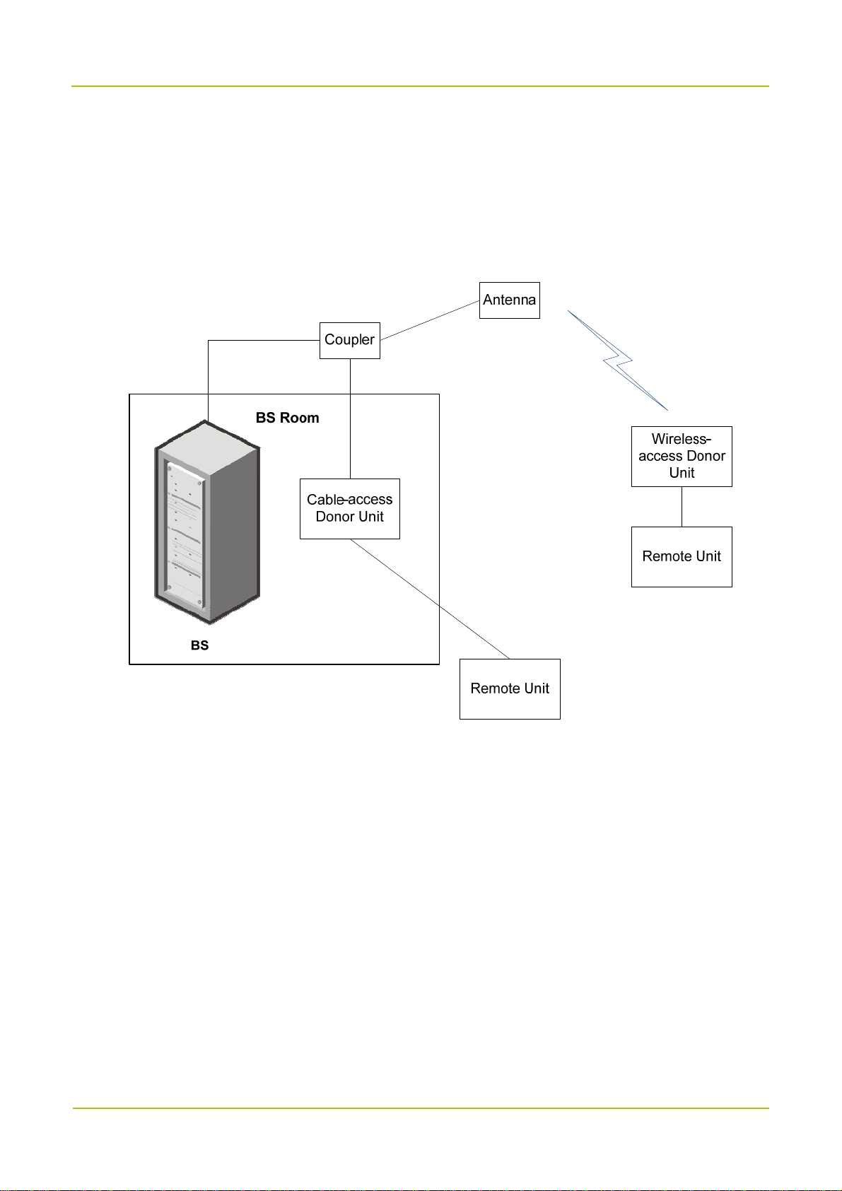
1.3 System Architecture........................................................................................................................... 3
1.3.1 Star Topology........................................................................................................................... 4
1.3.2 Chain Topology........................................................................................................................ 5
1.3.3 Ring Topology.......................................................................................................................... 5
1.3.4 Hybrid Topology ....................................................................................................................... 6
1.4 Specifications .................................................................................................................................... 6
2. Packing List......................................................................................................................................... 10
2.1 Cable-access Donor Unit................................................................................................................. 10
2.2 Wireless-access Donor Unit ............................................................................................................ 10
2.3 Remote Unit..................................................................................................................................... 10
3. Getting Started .................................................................................................................................... 11
3.1 Appearance ..................................................................................................................................... 11
3.2 Donor Unit Interfaces....................................................................................................................... 12
3.2.1 Cable-access Donor Unit....................................................................................................... 12
3.2.2 Wireless-access Donor Unit .................................................................................................. 13
3.3 Remote Unit Interfaces .................................................................................................................... 13
3.4 Interface Description........................................................................................................................ 14
3.5 Interface Definition........................................................................................................................... 15
3.6 LED Indicators ................................................................................................................................. 16
4. Installation ........................................................................................................................................... 18
4.1 Safety Information............................................................................................................................ 18
4.2 Installation Flow............................................................................................................................... 19
4.3 Preparation ...................................................................................................................................... 19
4.3.1 Environment .......................................................................................................................... 20
4.3.2 Instruments and Tools............................................................................................................ 21
4.3.3 Material Preparation .............................................................................................................. 21
4.4 Installing the Units ........................................................................................................................... 21
4.4.1 Installation Parts .................................................................................................................... 22
4.4.2 Installing the Product ............................................................................................................. 22
4.4.3 Cabling .................................................................................................................................. 27
4.5 Post-installation Check .................................................................................................................... 34
4.5.1 Checking the Installation........................................................................................................ 34
4.5.2 Checking the Device with Power On ..................................................................................... 34

Contents User Manual
ii
5. Power On and Power Off .................................................................................................................... 36
5.1 Powering On.................................................................................................................................... 36
5.2 Powering Off.................................................................................................................................... 36
6. Debugging ........................................................................................................................................... 37
6.1 Preparation ...................................................................................................................................... 37
6.2 Procedure ........................................................................................................................................ 37
6.2.1 Querying Parameters ............................................................................................................ 39
6.2.2 Setting Parameters................................................................................................................ 39
6.2.3 Upgrade................................................................................................................................. 41
6.2.4 Exporting the Logs................................................................................................................. 42
7. System Maintenance........................................................................................................................... 43
7.1 Care and Cleaning........................................................................................................................... 43
7.2 Routine Maintenance....................................................................................................................... 43
7.3 Alarm Handling ................................................................................................................................ 44
7.4 Troubleshooting ............................................................................................................................... 45
8. Appendix: Parameters........................................................................................................................ 46

User Manual Documentation Information
1
Documentation Information
This section describes the audiences, conventions and revision history of this document.
Intended Audience
This document is intended to be read by:
Sales engineers
Common users
Documentation Conventions
Icon Conventions
Icon Description
Tip Indicates information that can help you make better use of your product.
Note Indicates references that can further describe the related topics.
Caution Indicates situations that could cause data loss or equipment damage.
Warning Indicates situations that could cause minor personal injury.
Danger Indicates situations that could cause major personal injury or even death.
Notation Conventions
Item Description Example
Boldface
Denotes menus, tabs, parameter names,
window names, dialogue names, and
hardware buttons.
To save the configuration, click Apply.
The Log Level Settings dialogue
appears.
Press the PTT key.
" " Denotes messages, directories, file names, The screen displays "Invalid!"

Documentation Information User Manual
2
Item Description Example
folder names, and parameter values. Open "PDT_PSS.exe".
Go to "D:/opt/local".
In the Port text box, enter "22".
> Directs you to access a multi-level menu. Go to File >New.
Italic Denotes document titles.
For details about using the DWS, refer
to Dispatch Workstation User Guide.
Courier New Denotes commands and their execution
results.
To set the IP address, run the following
command:
vos-cmd - m name IP
Revision History
Document Version Product Version Release Date Description
03 V1.0 August 2018
Added descriptions on digital repeaters
of low configuration.
Added detail steps in “Setting
Parameters”.
02 V1.0 May 2018
Added contents on the wireless-access donor
unit and band-selective repeater.
01 V1.0 March 2018 Modified the names of several devices.
00 V1.0 January 2018 Initial release.

User Manual Introduction
3
1. Introduction
1.1 Product Description
DS-9300 Digital Repeater ("DS-9300") is the new generation of repeater developed by Hytera. Using
optical fibers to transmit signal, DS-9300 effectively makes up for the signal decline between base stations
(BSs) and radios.
Featuring low transmission loss and easy wiring, DS-9300 delivers long distance transmission of
multicarrier signals and strong and dynamic signal coverage. It is an ideal solution to blind zones such as
populated urban areas, large exhibition halls, stadiums, campuses, tunnels, metro stations and etc.
DS-9300 has two types of configurations, including low configuration and high configuration, which have
the same appearance but different features.
1.2 Highlights
DS-9300 has the following highlights:
Flexible monitoring
DS-9300 provides remote monitoring (through IP network) and local monitoring (through RS232 serial
port). Users can manage all devices through the network management system, or remotely query,
configure and upgrade a single device.
Excellent hardware performance
DS-9300 has low intermodulation noise, strong out-of-band rejection, low interference and great
interference resistance.
Software-Defined Radio (SDR) Technology
DS-9300 achieves uplink squelch, delay compensation, carrier rejection, digital multi-carrier and etc
with the SDR Technology. It supports multiple network topologies such as star, chain, ring and hybrid
topologies.
Effective mechanical design
DS-9300 is compact and portable with effective heat dissipation and resistance to water, dust and salt
spray. Various installation methods are available for DS-9300 including wall-mounting, pole-mounting
and etc.
1.3 System Architecture
DS-9300 consists of the donor unit and the remote unit. They transparently convey and amplify the

Introduction User Manual
4
wireless signal between the BS and the radios. Donor unit includes the cable-access donor unit and the
wireless-access donor unit. The cable-access donor unit is mounted into a 19-inch rack at the BS location
while the wireless-access donor unit can be installed remotely from the BS. The remote unit is installed
away from the donor unit over a fiber link. The following figure shows the networking of DS-9300 and the
BS.
Various topologies are available for networking between the donor and the remote units, including star,
chain, ring and hybrid topologies.
1.3.1 Star Topology
Low Configuration
For low configuration of star topology, each SFP port of the donor unit can connect to up to four remote
units, while one donor unit can connect to at most four remote units (N≤4).

User Manual Introduction
5
Donor Unit
0
1
2
3
Remote
Unit
0 1
Remote
Unit
0 1
Remote
Unit
0 1
Remote
Unit
0 1
Donor Unit
0
1
2
3
Remote
Unit
0 1
Remote
Unit
0 1
High Configuration
For high configuration of star topology, each SFP port of the donor unit can connect to up to eight remote
units, while one donor unit can connect to at most 16 remote units (N≤16).
1.3.2 Chain Topology
Low Configuration
For low configuration of chain topology, only one of the SFP ports on the donor unit is used and it can
connect to at most four remote units (N≤4).
Donor Unit Remote
Unit 1
Remote
Unit N
Remote
Unit 2
0 1 0 01 1
High Configuration
For high configuration of chain topology, the SFP port on the donor unit can connect to at most eight
remote units (N≤8).
1.3.3 Ring Topology
Low Configuration
For low configuration of ring topology, the donor unit can form at most two rings, with each ring can
connect to up to two remote units; or the donor unit forms one ring and connects to four remote units.

450-460MHz(UL)
1 Frequency Range
Introduction User Manual
6
High Configuration
For high configuration of ring topology, at most two rings can be formed on the donor unit, with each ring
can connect to up to eight remote units (N≤8).
1.3.4 Hybrid Topology
Low Configuration
For low configuration of hybrid topology, each SFP port of the donor unit can connect up to four remote
units, while one donor unit can connect to at most four remote units.
High Configuration
For high configuration of hybrid topology, each SFP port of the donor unit can connect up to eight remote
units, while one donor unit can connect to at most 16 remote units.
1.4 Specifications
No. Item
Specifications
Downlink Uplink
460-470MHz(DL)

4 Max. Output Power 5W
User Manual Introduction
7
No. Item
Specifications
Downlink Uplink
5 MHz (operating bandwidth)
2 Channel Bandwidth 25 kHz
3 Channel Capacity 1–8
1W
5 Max. Gain
Cable-access: 50 dB±3
dB
Wireless-access: 95
dB±3 dB
Cable-access: 45
dB±3 dB
Wireless-access: 90
dB± 3 dB
6 Gain Adjustment Range/Step 30 dB/1 dB
7 Gain Adjustment Error ≤1 dB@ gain of 0–20 dB
≤1.5 dB@ gain of 21–30 dB
8 Noise Figure Wireless-access: ≤5 dB ≤5 dB
9 Max. Input Level
Cable-access: 10 dBm
Wireless-access: –10
dBm
–10 dBm
10 Automatic Level Control (ALC)
Output power variation < 2 dB or be off when adding 10
dB at max output power.
Control range≥20 dB.
11 In-Band Ripple ≤3 dB
12 Input/Output VSWR ≤1.5
13 Delay ≤35 μs
14 Frequency Offset ≤5×10⁻⁸ ppm
15
Spurious
Emission
In-band ≤–15 dBm/30 kHz
Out-of-band (2.5
MHz away from the
≤–36 dBm@9 kHz to 1 GHz
≤–30 dBm@1 GHz to 12.75 GHz

Introduction User Manual
8
No. Item
Specifications
Downlink Uplink
band edge
16
Intermodulation
Attenuation
In-band
≤–40 dBc@RBW3 kHz
8 CH 75 kHz Carrier Spacing
≤–45 dBc@RBW3 kHz
2 CH 75 kHz Carrier Spacing
Out-of-band (2.5
MHz away from the
band edge)
≤–36 dBm/100 kHz@9 kHz to 1 GHz
≤–30 dBm/1 MHz@1 GHz to 12.75 GHz
17 Out-of-band Rejection (–6 dB)
≤–20 dBc@±50 kHz
≤–25 dBc@±75 kHz
≤–30 dBc@±125 kHz
≤–63 dBc@±250 kHz
≤–67 dBc@±500 kHz
18 Optical Bypass (optional)
When the remote unit is powered down or the optical
path is faulty, the optical path is automatically bypassed,
and other cascaded remote units are not affected.
19 Optical Loop
When the remote unit is powered down or the optical
path is interrupted, other cascaded devices can work
normally through the loop.
20 Network Topology Star, Chain, Ring, Hybrid and etc.
21 Optical Transmission Distance ≥20 km
22 Transmission Rate 1.25 GB/s, 2.5 GB/s, 3.02 GB/s, 6.04 GB/s (optional)
23 Optical TX Power –9.5 dBm to –3 dBm
24 Max. Optical RX Sensitivity –20 dBm
25 RF Connector N/F, 50 Ω

User Manual Introduction
9
No. Item
Specifications
Downlink Uplink
26 Fiber Connector
Donor Unit: LC/UPC
Remote Unit: LC/UPC
27 Power Supply Donor Unit /Remote Unit: 90 V to 264 V AC
28
Power
Consumption
Donor Unit
Cable-access: ≤30 W
Wireless-access: ≤100 W
Remote Unit ≤100 W
29 Ingress Protection Rating
Cable-access Donor Unit: IP20
Wireless-access Donor Unit: IP65
Remote Unit: IP65
30 Safety IEC 60950 Compliance
31 EMC IEC 61000 class B Compliance
32 Dimensions
Cable-access Donor Unit: 44 mm x 442 mm x 320
mm
Wireless-access Donor Unit: 142 mm x 300 mm x
385 mm
Remote Unit: 142 mm x 300 mm x 385 mm
33 Monitoring
Supports local monitoring and remote monitoring.
Local monitoring: RS232
Remote monitoring: SNMP
Internal Communication: RS485
34 MTBF ≥100,000 h
35 Operating Temperature
Cable-access Donor Unit: –10°C to +45°C
Wireless-access Donor Unit: –25°C to +55°C
Remote Unit: –25°C to +55°C
36 Storage Temperature –40°C to +85°C

Packing List User Manual
10
2. Packing List
Please unpack carefully and check that all items listed below are received. If any item is missing or
damaged, please contact us or your dealer.
2.1 Cable-access Donor Unit
Item Qty. Item Qty.
Main Unit 1 Cable Kit 1
Packing material for 19-inch Rack 1 Optical Cable Kit 1
Square Nut Kit 4 Power Cord 1
Crown Screw 4 Documentation Kit 1
2.2 Wireless-access Donor Unit
Item Qty. Item Qty.
Main Unit 1 Signal Cable (8-core) 1
Packing material 1 Power Cord 1
Mechanical parts of
Die Casting Machine installation
1 Cable Kit 1
Signal Cable (1-core) 1 Optical Cable Kit 1
Documentation Kit 1 / /
2.3 Remote Unit
Item Qty. Item Qty.
Main Unit 1 Signal Cable (8-core) 1
Packing material 1 Power Cord 1
Mechanical parts of
Die Casting Machine installation
1 Optical Cable Kit 1
Signal Cable (1-core) 1 SFP Optical Module 2
Documentation Kit 1 / /

User Manual Getting Started
11
3. Getting Started
3.1 Appearance
DS-9300 adopts modular design. For the wireless-access donor unit and the remote unit, its LED
indicators and connectors are provided on the front and rear panels of the rack. The following figure shows
the appearance of the remote unit.
For the donor unit, its LED indicators are provided on the right side and connectors are provided on its
bottom and right side. The following figure shows the appearance of the donor unit.

Getting Started User Manual
12
3.2 Donor Unit Interfaces
3.2.1 Cable-access Donor Unit
12
345 6 7 8 1010 11
9

User Manual Getting Started
13
3.2.2 Wireless-access Donor Unit
13 14
15
6
1789
11
312
3.3 Remote Unit Interfaces
1
12 13 11
16
6789
14

Getting Started User Manual
14
3.4 Interface Description
No. Label Meaning Connector Description
1 / LED indicators / See "3.6".
2 POWER Power switch
Single-pole-doubl
e-throw switch
/
3 MANT
Modem antenna
connector
SMA-F Reserved.
4 BS/TX
ANT port of the
duplexer, or TX
port of the BS
N/F
Connected to the ANT port of the
duplexer, or connected to the TX port of
the BS if the duplexer does not exist.
5 RX RX port of the BS N/F
Connected to the RX port of the BS if the
duplexer does not exist.
6 LOC
Local debug
interface
3-pin connector
Connected to computer through the serial
cable for debugging and monitoring.
7 CPRI 0–3 Optical port
SFP connector,
dual-layer
The donor unit connects to remote units
through CPRI interface.
8 IP
Remote
monitoring port
RJ45 port
Connected to computer through the
network cable for remote debugging and
monitoring.
9 Debug
Optical module
debug interface
RJ45 port
Interface for board debugging, used by
R&D engineers.
10
AC
90-264 V
Power inlet
3-pin AC
connector
/
11 GND Ground terminal / /
12 AC Power inlet
3-pin round
electric connector
AC power inlet.
13 EXM External alarm port
8-pin round
electric connector
Connected to external devices that need
alarm monitoring.
14 LCT Alarm port for 6-pin round Donor Unit: Monitors location change
Table of contents
Other Hytera Repeater manuals

Hytera
Hytera RD98XSU2 User manual

Hytera
Hytera DMR Quick start guide

Hytera
Hytera RD625 User manual

Hytera
Hytera HR65X User manual

Hytera
Hytera RD965 User manual

Hytera
Hytera RD985 User manual

Hytera
Hytera H Series User manual

Hytera
Hytera RD106X User manual

Hytera
Hytera RD98 Series User manual

Hytera
Hytera E-pole 100 User manual

Hytera
Hytera RD98XS User manual

Hytera
Hytera RD98XSU User manual

Hytera
Hytera RD98 Series User manual

Hytera
Hytera RD98X series User manual

Hytera
Hytera RD98X series User manual

Hytera
Hytera RD988 U5 User manual

Hytera
Hytera RD620 User manual

Hytera
Hytera 982i User manual

Hytera
Hytera HR106X User manual

Hytera
Hytera RD62 series User manual