HYTROL HSQ Manual

1
Installation
and
Maintenance
Manual
with Safety Information
and Parts List
RECOMMENDED SPARE PARTS HIGHLIGHTED IN GRAY
Manual
de Instalación
y
Mantenimiento
con Información sobre Seguridad
y Lista de Refacciones
LAS REFACCIONES RECOMENDADAS SE RESALTAN EN GRIS
IMPORTANT!
DO NOT DESTROY
¡IMPORTANTE!
NO DESTRUIR
HYTROL | Jonesboro, Arkansas
Copyright © 1947–2021 Hytrol. All rights reserved.
Effective August 2021
Bulletin #743
Model HSQ

2
TABLE OF CONTENTS
INTRODUCTION
Receiving and Uncrating ....................2
How To Order Replacement Parts ............2
SAFETY INFORMATION
Installation ...............................3
Operation................................3
Maintenance .............................3
INSTALLATION
Support Installation ........................4
Ceiling Hanger Installation ..................4
Belt Installation .........................4, 5
Conveyor Set-Up..........................4
Electrical Equipment .......................4
OPERATION
Conveyor Start-Up.........................6
MAINTENANCE
Belt Tracking . . . . . . . . . . . . . . . . . . . . . . . . . . . . .6
Troubleshooting...........................7
Maintenance Checklist ............ Back Cover
REPLACEMENT PARTS
Model HSQ Parts Drawing & List
4"End Drive & Parts List....................8
6" End Drive & Parts List....................9
Spanish Version ...........................10
INTRODUCTION
This manual provides guidelines and procedures for installing, operating,
and maintaining your conveyor. A complete parts list is provided with
recommended spare parts highlighted in gray. Important safety information is
also provided throughout the manual. For safety to personnel and for proper
operation of your conveyor, it is recommended that you read and follow the
instructions provided in this manual.
• Receiving and Uncrating
1. Check the number of items received against the bill of lading.
2. Examine condition of equipment to determine if any damage
occurred during shipment.
3. Move all crates to area of installation.
4. Remove crating and check for optional equipment that may be fastened
to the conveyor. Make sure these parts (or any foreign pieces) are removed.
• How to Order Replacement Parts
Included in this manual are parts drawings with complete replacement parts
lists. Minor fasteners, such as nuts and bolts, are not included.
When ordering replacement parts:
1. Contact Dealer from whom conveyor was purchased or nearest HYTROL
Integration Partner.
2. Give Conveyor Model Number and Serial Number or HYTROL Factory
Order Number.
3. Give complete description from Parts List.
4. Give type of drive. Example—8" End Drive, 8" Center Drive, etc.
5. If you are in a breakdown situation, call our Customer Care team at
1-844-4HYTROL.
HYTROL Serial Number
(Located near Drive on Powered Models).
NOTE: If damage has occurred or freight is missing,
Contact your Hytrol Integration Partner.
OAW
ANCHO TOTAL
BELT WIDTH
ANCHO DEL LA BANDA
Belt Width 35.6" 43.5" 48.5" 61"
Overall Width 40" 46" 52" 64.5"
Jonesboro, Arkansas
Serial # 615415
Model
QR Code
YEAR

3
SAFETY INFORMATION
• Installation
GUARDS AND GUARDING
Interfacing of Equipment. When two or more pieces of equipment
are interfaced, special attention shall be given to the interfaced area
to ensure the presence of adequate guarding and safety devices.
Guarding Exceptions. Whenever conditions prevail that would
require guarding under these standards, but such guarding would
render the conveyor unusable, prominent warning means shall be
provided in the area or on the equipment in lieu of guarding.
Guarded by Location or Position. Where necessary for the
protection of employees from hazards, all exposed moving machinery
parts that present a hazard to employees at their work station shall
be mechanically or electrically guarded, or guarded by location or
position.
• Remoteness from frequent presence of public or employed
personnel shall constitute guarding by location.
• When a conveyor passes over a walkway, roadway, or work
station, it is considered guarded solely by location or position
if all moving parts are at least 8 ft. (2.44 m) above the oor or
walking surface or are otherwise located so that the employee
cannot inadvertently come in contact with hazardous moving
parts.
• Although overhead conveyors may be guarded by location, spill
guards, pan guards, or equivalent shall be provided if the product
may fall o the conveyor for any reason and if personnel would
be endangered.
HEADROOM
• When conveyors are installed above exit passageways, aisles,
or corridors, there shall be provided a minimum clearance of 6
ft. 8 in. (2.032 m) measured vertically from the oor or walking
surface to the lowest part of the conveyor or guards.
• Where system function will be impaired by providing the
minimum clearance of 6 ft. 8 in. (2.032 m) through an emergency
clearance, alternate passageways shall be provided.
• It is permissible to allow passage under conveyors with less
than 6 ft. 8 in. (2.032 m) clearance from the oor for other than
emergency exits if a suitable warning indicates low headroom.
• Operation
A) Only trained employees shall be permitted to operate conveyors.
Training shall include instruction in operation under normal conditions
and emergency situations.
B) Where employee safety is dependent upon stopping and/or
starting devices, they shall be kept free of obstructions to permit
ready access.
C) The area around loading and unloading points shall be kept clear
of obstructions which could endanger personnel.
D) No person shall ride the load-carrying element of a conveyor
under any circumstances unless that person is specically authorized
by the owner or employer to do so. Under those circumstances, such
employee shall only ride a conveyor which incorporates within its
supporting structure platforms or control stations specically designed
for carrying personnel. Under no circumstances shall any person ride
on any element of a vertical conveyor.
E) Personnel working on or near a conveyor shall be instructed as to
the location and operation of pertinent stopping devices.
F) A conveyor shall be used to transport only material it is capable
of handling safely.
G) Under no circumstances shall the safety characteristics of the
conveyor be altered if such alterations would endanger personnel.
H) Routine inspections and preventive and corrective maintenance
programs shall be conducted to ensure that all safety features and
devices are retained and function properly.
I) Personnel should be alerted to the potential hazard of entanglement
in conveyors caused by items such as long hair, loose clothing, and
jewelry.
J) Conveyors shall not be maintained or serviced while in operation
unless proper maintenance or service requires the conveyor to be in
motion. In this case, personnel shall be made aware of the hazards
and how the task may be safely accomplished.
K) Conveyor owners should ensure proper safety labels are axed
to the conveyor, to warn of particular hazards involved in operation of
their conveyors.
• Maintenance
Refer to ANSI Z244.1-1982, American National Standard for Personnel Protection
– Lockout/Tagout of Energy Sources – Minimum Safety Requirements and OSHA
Standard Number 29 CFR 1910.147 “The Control of Hazardous Energy (Lockout/
Tagout).”
• All maintenance, including lubrication and adjustments, shall be
performed only by qualied and trained personnel.
• It is important that a maintenance program be established
to ensure that all conveyor components are maintained in a
condition which does not constitute a hazard to personnel.
• When a conveyor is stopped for maintenance purposes, starting
devices or powered accessories shall be locked or tagged out
in accordance with a formalized procedure designed to protect
all persons or groups involved with the conveyor against an
unexpected start.
• Replace all safety devices and guards before starting equipment
for normal operation.
• Whenever practical, DO NOT lubricate conveyors while they are
in motion. Only trained personnel who are aware of the hazard
of the conveyor in motion shall be allowed to lubricate.
Safety Guards
Maintain all guards and safety devices IN POSITION and IN SAFE
REPAIR.
Safety Labels
In an eort to reduce the possibility of injury to personnel working
around HYTROL conveying equipment, safety labels are placed at
various points on the equipment to alert them of potential hazards.
Please check equipment and note all safety labels. Make certain
your personnel are alerted to and obey these warnings. See Safety
Manual for examples of warning labels.
CAUTION! Because of the many moving parts on the conveyor, all
personnel in the area of the conveyor need to be warned that the conveyor
is about to be started.
REMEMBER Do not remove, reuse or modify material handling equipment
for any purpose other than it’s original intended use.

4
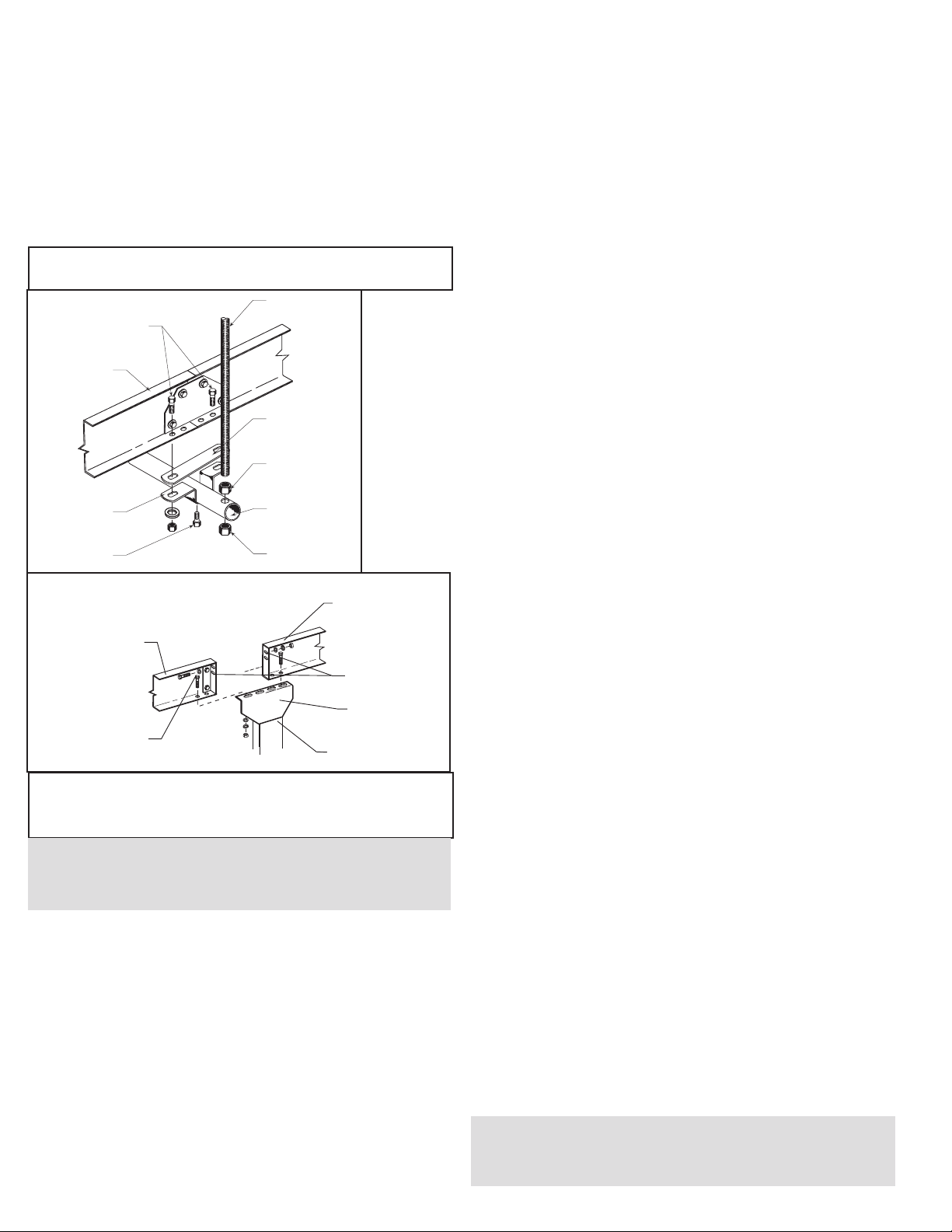
• Ceiling Hanger Installation
If conveyors are to be used in an overhead application, ceiling hangers may
have been supplied in place of floor supports.
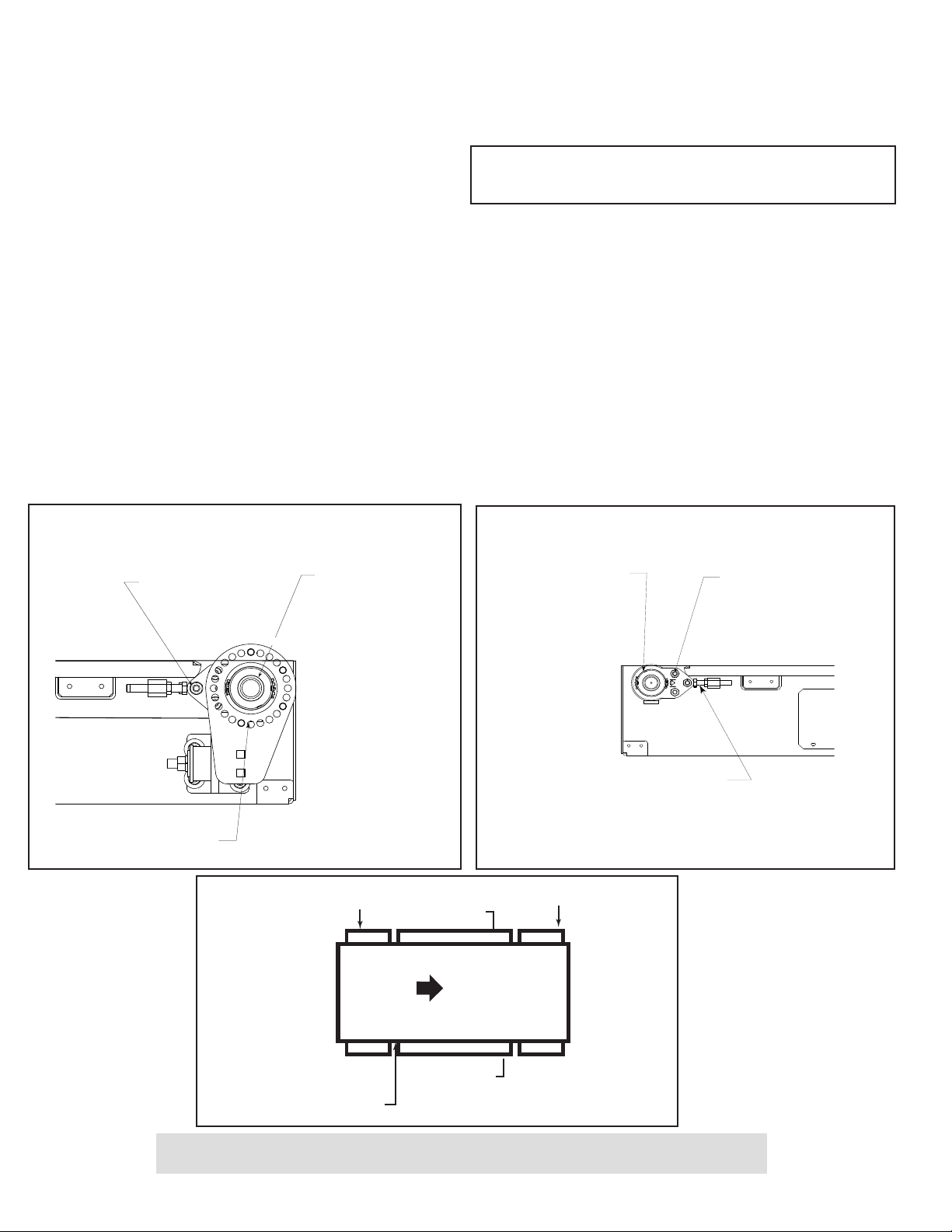
Figure 4A shows how a ceiling hanger mounts to a conveyor section. Ceiling
hangers should be mounted at section joints.
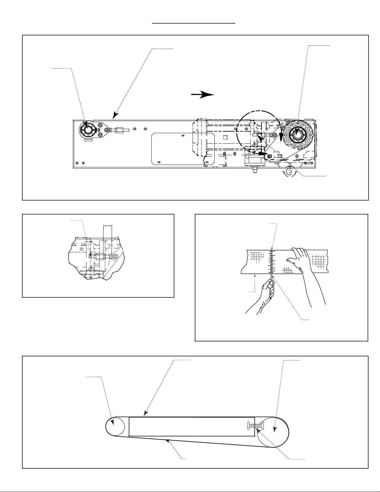
• Belt Installation
The conveyor belt has been cut to the proper length and lacing installed at the
factory. To install follow these steps:
1. Thread belt through conveyor as shown (Figure 5D).
2. Pull ends together and insert lacing pin (Figure 5C).
3. Adjust belt tension with take-up pulley or tail pulley. Keep pulley square by
moving both take-up bolts an equal amount. Maintain enough tension so drive
pulley will not slip when carrying the rated load.
4. Track belt per instructions on Page 6.
• Conveyor Set-Up
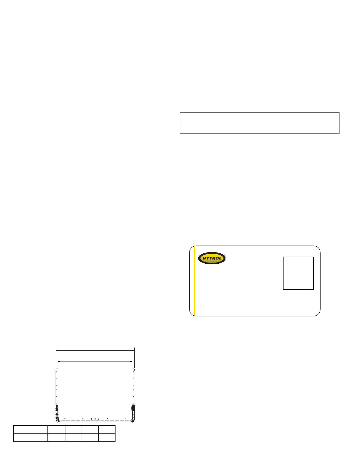
1. Mark a chalk line on floor to locate center of the conveyor (Floor Mounted
Conveyors).
2. Place section in position.
3. Check to see that conveyor is level across width and length of unit. Adjust
supports and ceiling hangers as necessary.
4. Install electrical controls and wire motor.
5. Install and track belt per instructions on Belt Installation and
Belt Tracking.
• Electrical Equipment
CONTROLS
Electrical Code: All motor controls and wiring shall conform to the National
Electrical Code (Article 670 or other applicable articles) as published by
the National Fire Protection Association and as approved by the American
Standards Institute, Inc.
CONTROL STATIONS
A) Control stations should be so arranged and located that the operation of
the equipment is visible from them, and shall be clearly marked or labeled to
indicate the function controlled.
B) A conveyor which would cause injury when started shall not be started
until employees in the area are alerted by a signal or by a designated person
that the conveyor is about to start.
When a conveyor would cause injury when started and is automatically
controlled or must be controlled from a remote location, an audible device
shall be provided which can be clearly heard at all points along the conveyor
wherepersonnel may be present. The warning device shall be actuated by the
controller device starting the conveyor and shall continue for a required period
of time before the conveyor starts. A flashing light or similar visual warning
may be used in conjunction with or in place of the audible device if more
effective in particular circumstances.
Where system function would be seriously hindered or adversely
affected by the required time delay or where the intent of the warning may
be misinterpreted (i.e., a work area with many different conveyors and allied
devices), clear, concise, and legible warning shall be provided. The warning
shall indicate that conveyors and allied equipment may be started at any time,
that danger exists, and that personnel must keep clear. The warnings shall be
provided along the conveyor at areas not guarded by position or location.
C) Remotely and automatically controlled conveyors, and conveyors where
operator stations are not manned or are beyond voice and visual contact from
drive areas, loading areas, transfer points, and other potentially hazardous
locations on the conveyor path not guarded by location, position, or guards,
shall be furnished with emergency stop buttons, pull cords, limit switches, or
similar emergency stop devices.
All such emergency stop devices shall be easily identifiable in the
immediate vicinity of such locations unless guarded by location, position, or
guards. Where the design, function, and operation of such conveyor clearly is
not hazardous to personnel, an emergency stop device is not required.
The emergency stop device shall act directly on the control of the
conveyor concerned and shall not depend on the stopping of any other
equipment. The emergency stop devices shall be installed so that they cannot
be overridden from other locations.
D) Inactive and unused actuators, controllers, and wiring should be removed
from control stations and panel boards, together with obsolete diagrams,
indicators, control labels, and other material which serve to confuse the
operator.
SAFETY DEVICES
A) All safety devices, including wiring of electrical safety devices, shall be
arranged to operate in a “Fail-Safe” manner, that is, if power failure or failure
of the device itself would occur, a hazardous condition must not result.
B) Emergency Stops and Restarts. Conveyor controls shall be so arranged
that, in case of emergency stop, manual reset or start at the location where
the emergency stop was initiated, shall be required of the conveyor(s) and
associated equipment to resume operation.
C) Before restarting a conveyor which has been stopped because of an
emergency, an inspection of the conveyor shall be made and the cause of
the stoppage determined. The starting device shall be locked out before
any attempt is made to remove the cause of stoppage, unless operation is
necessary to determine the cause or to safely remove the stoppage.
Refer to ANSI Z244.1-1982, American National Standard for Personnel
Protection – Lockout/Tagout of Energy Sources – Minimum Safety
Requirements and OSHA Standard Number 29 CFR 1910.147 “The Control
of Hazardous Energy (Lockout/Tagout).”
NOTE: When installing ceiling hanger rods in an existing building, all
methods of attachment must comply with local building codes.
NOTE: If belt ends cannot be pulled together by hand, it may be
necessary to loosen take-ups (at tail pulley, etc.), minimum position
or use a belt puller so lacing pin can be easily inserted.
CAUTION! Excessive slippage will reduce belt life and damage drive
pulley lagging. Never apply more tension than is needed.
Over-tension will cause extra wear to belt and bearings and will require
extra power from drive.
INSTALLATION
• Support Installation
1. Determine primary direction of product flow. Figure 5A indicates the preferred flow as related to the drive.
2. Refer to “Match-Mark” numbers on ends of conveyor sections. Position them in sequence near the area of installation.
3. Attach supports to both ends of drive section and to one end of intermediate or tail sections (Figure 4B). Hand tighten bolts only at this time. Conveyors
angle of incline will determine where the knee brace mounting brackets are to be placed when required.
4. Adjust elevation to required height.
SUPPORT PIPE
(TUBO DE SOPORTE)
JAM NUT
(CONTRA TUERCA)
SPACER
(ESPACIADOR)
CEILING HANGER ROD
(VARILLA COLGADA
AL TECHO)
JAM NUT
(CONTRA TUERCA)
PIPE RETAINER
(ABRAZADERA)
LOCK BOLT
(TORNILLO CANDADO)
SIDE CHANNEL
(CANAL LATERAL)
MOUNTING BOLTS
(TORNILLOS DE MONTAJE)
MATCH-MARK
MATCH-MARK
WARNING!
Electrical controls shall be installed and wired by a qualified electrician.
Wiring information for the motor and controls are furnished by the
equipment manufacturer.
FIGURE 4A
SIDE CHANNEL
(CANAL LATERAL)
MOUNTING BOLT
(TORNILLO DE MONTAJE)
SIDE CHANNEL
(CANAL LATERAL)
BUTT COUPLINGS
(ACOPLES DE
EXTREMO )
PIVOT PLATE
(PLACA PIVOTE)
STATIONARY SUPPORT
(SOPORTE ESTACIONARIO)
FIGURE 4B

5
A
BELT LACING
BELT
LACING PIN
(ENLACE DE BANDA)
(BANDA)
(PASADOR DE ENLACE)
FIGURE 5C
FIGURE 5A DRIVE
PULLEY
BELT (TOP SIDE)
BELT FLOW
BELT INSTALLATION—END DRIVE
TAIL
PULLEY
TAKE-UP BOLT
(POLEA DE
RETORNO)
(BANDA [LADO SUPERIOR])
(FLUJO DE BANDA)
(POLEA
MOTRIZ)
(TORNILLO TENSOR)
(INSTALACIÓN DE LA BANDA—UNIDAD MOTRIZ DE EXTREMO)
• Belt Installation
TAIL
PULLEY
(POLEA DE
RETORNO)
BELT (TOP SIDE)
(BANDA [LADO SUPERIOR])
DRIVE PULLEY
(POLEA MOTRIZ)
TAKE-UP BOLT
(TORNILLO TENSOR)
BELT (BOTTOM SIDE)
(BANDA [LADO INFERIOR])
FIGURE 5D
“A”
DIMENSION
TAKE-UP BOLT
(TORNILLO TENSOR) (DIMENSIÓN)
DETAIL A SCALE 1/4
(DETALLE A ESCALA 1/4)
BELT PATH
FIGURE 5B
(RUTA DE LA CORREA)

6
DRIVE PULLEY BEARING
(RODAMIENTO DE LA
POLEA MOTRIZ)
ADJUSTMENT
BOLTS
(TORNILLOS
DE AJUSTE)
DRIVE PULLEY
(POLEA MOTRIZ)
FIGURE 6A
TAIL PULLEY
(POLEA DE
RETORNO)
TAKE-UP BOLT
(TORNILLO
TENSOR)
ADJUSTMENT
BOLTS
(TORNILLOS DE
AJUSTE)
SQUARING THE TAIL PULLEY
(ENCUADRANDO LA POLEA DE RETORNO)
FIGURE 6B
• Belt Tracking
FIGURE 6C
FLOW
SIDE “X”
DRIVE PULLEY
BELT
INFEED
DISCHARGE
TAIL PULLEY
SIDE “Y”
(POLEA DE RETORNO) (POLEA MOTRIZ/DE RETORNO)
(LADO “Y”)
(BANDA)
(LADO “X”)
(FLUJO)
(ALIMENTACIÓN)
(DESCARGA)
CAUTION!
Only trained personnel should track conveyor belt which must be done while conveyor is in operation.
OPERATION
• Conveyor Start-Up
Before conveyor is turned on, check for foreign objects that may have been
left inside conveyor during installation. These objects could cause serious
damage during start-up.
After conveyor has been turned on and is operating, check motors, reducers,
and moving parts to make sure they are working freely.
MAINTENANCE
• Belt Tracking
HOW IS THE CONVEYOR BELT TRACKED
The belt is tracking by adjusting: Drive Pulley and Tail Pulley. The same
tracking principles apply to conveyors supplied with end drives, center drives,
or underside take-ups.
PRE-TRACKING INSPECTION
Before attempting to physically track the belt:
1. Make sure conveyor is level across the width and length of unit. Adjust
supports as necessary.
2. Check to make sure: Drive Pulley and Tail Pulley are square with conveyor
bed. See illustrations Figure 6A, 6B, and 6C. Dimension “A” should be equal
on both sides of the unit (Figure 5B).
3. Make sure belt has been properly threaded through conveyor. See Figure
5D.
4. Make sure belt lacing has been installed correctly and is square with the
belt (Figure 5C).
5. Check for improper loading.
IMPORTANT: When belt tracking adjustments are made, they should be
minor (1/16 in. at a time, etc., should be sufficient).
Give the belt adequate time to react to the adjustments. It may take several
complete revolutions around the conveyor for the belt to begin tracking
properly on long, slow conveyor lines.
Feed should be in direction of belt travel, centered on belt.
A) Stand at tail pulley looking toward drive and note what direction belt is
traveling.
B) Having observed belt and determined tracking problem, follow procedures
in “How to Steer The Belt.”
HOW TO STEER THE BELT
Condition 1: When the belt is running in the direction (FLOW) with the arrow,
but tracking (drifting) towards Side “X,” move the Infeed Tail Pulley nearest
the INFEED end of Side “X” towards the INFEED end of the conveyor.
Condition 2: When the belt is running in the direction (FLOW) with the arrow,
but tracking (drifting) towards Side “Y,” move the Infeed Tail Pulley nearest
the INFEED end of Side “Y” towards the INFEED end of the conveyor.
These instructions differ for units that contain Snub Rollers.
The HSQ is not designed to run in reverse.
If belt continues to track improperly, re-check all items covered in “Pre-
Tracking Inspection” on Page 6 and make corrections as necessary.
NOTE: In all conditions, you are viewing the Conveyor Belt from the
INFEED end. All corrections will be made from the INFEED end of
conveyor.

7
• Troubleshooting
The following charts list possible problems that may occur in the operation of the conveyor.
TROUBLESHOOTING DRIVES
TROUBLE CAUSE SOLUTION
Conveyor will not start or
motor quits frequently.
1) Motor is overloaded.
2) Motor is drawing too much current.
1) Check for overloading of conveyor.
2) Check heater or circuit breaker and change if necessary.
Loud popping or grinding
noise.
1) Defective bearing.
2) Loose set screws in bearing.
1) Replace bearing.
2) Tighten set screw.
Motor or reducer
overheating.
1) Conveyor is overloaded.
2) Low voltage to motor.
3) Low lubricant level in reducer.
1) Check capacity of conveyor and reduce load to recommended level.
2) Have electrician check and correct as necessary.
3) Relubricate per manufacturer’s recommendations. For HYTROL
reducer, refer to Installation and Maintenance Manual #684 (Speed
Reducers 4A, 4AC, 5A, 5AC).
Belt does not move, but
drive runs.
1) Conveyor is overloaded.
2) Belt is too loose.
3) Lagging on drive pulley is worn.
1) Reduce load.
2) Use belt take-up to tighten belt.
3) Replace drive pulley lagging and tighten belt.
TROUBLESHOOTING DRIVE BELT TRACKING
TROUBLE CAUSE SOLUTION
Entire length of belt
creeps off at one spot
only.
1) Conveyor section not level or square.
2) Material build-up on pulleys or idlers.
1) Make necessary adjustments to supports.
2) Remove residue from pulleys or idlers. Install belt, cleaners, or
scrappers if possible.
Belt creeps to one side at
tail pulley.
1) Tail pulley not properly aligned or square with
bed.
1) Adjust as necessary. See “Belt Tracking Pre-Tracking Inspection” in
this manual for details.
Entire belt creeps to one
side.
1) Conveyor not straight.
2) Conveyor not level.
3) Material build-up on rollers, pulleys, or idlers.
1) Re-align bed sections as necessary.
2) Correct as necessary.
3) Remove residue and install belt cleaners or scrapers if possible

8
• Model HSQ Parts Drawing & Parts List (4" End Drive)
Dibujo de Partes y Lista de Partes del Modelo HSQ (Unidad Motriz de Extremo de 4")
4
6
27
5
8
1
7
3
791
3
10
11
5
14 15
6
7
13
Ref. # Description
1
2
3
4
5
4'0" Side Channel Weld, Right Hand - Queue Drive
1/2-13" x 1-1/2" Carriage Bolt
4'0" Bed Pan Weld
4" Idler Pulley
Bed Spacer - 43"
6
7
8
9
10
4'0" Side Channel Weld, Left Hand
Bearing - 3-Bolt Bracket Flange - 1-7/16"
4" Drive Pulley
1/2-13" x 3-1/2" Hex Bolt
1/2-13 Hex Jam Nut
11
12
13
Access Cover - 12-1/2"
Torque Arm Weld, Right Hand
Torque Arm Bushing Mounting Kit

9
•
Model HSQ Parts Drawing & Parts List (6" End Drive)
Dibujo de Partes y Lista de Partes del Modelo HSQ (Unidad Motriz de Extremo de 6")
4
628
9
3
2
7
1
9
2
3
1
10
7
11 12 13 14 5114
3
9
6
5
Ref. # Description
1
2
3
4
5
4'0" Side Channel Weld, Right Hand - Queue Drive
1/2-13" x 1-1/2" Carriage Bolt
4'0" Bed Pan Weld
4" Idler Pulley
Bed Spacer - 43"
6
7
8
9
10
4'0" Side Channel Weld, Left Hand
Bearing - 3-Bolt Bracket Flange - 1-7/16"
Bearing - 3-Bolt Bracket Flange - 1-15/16"
6" Drive Pulley
1/2-13" x 3-1/2" Hex Bolt
11
12
13
14
1/2-13 Hex Jam Nut
Access Cover - 12-1/2"
Torque Arm Weld, Right Hand
Torque Arm Bushing Mounting Kit

10
ÍNDICE
INTRODUCCIÓN
Recepción y desembalaje ..................10
Cómo solicitar repuestos...................10
INFORMACIÓN DE SEGURIDAD
Instalación ..............................11
Operación ..............................11
Mantenimiento...........................11
INSTALACIÓN
Instalación del soporte ....................12
Instalación del soporte colgante a techo.......12
Instalación de la correa .................12, 13
Configuración del transportador .............12
Equipos eléctricos ........................12
OPERACIÓN
Arranque del transportador .................14
MANTENIMIENTO
Alineación de la correa ....................14
Solución de problemas ....................15
Lista de Mantenimiento Preventivo . Contraportada
REPUESTOS
Listado y dibujo de piezas del modelo HSQ
Accionamiento de extremo de 4" y listado
de piezas ................................8
Accionamiento de extremo de 6" y listado
de piezas ................................9
INTRODUCCIÓN
Este manual proporciona pautas y procedimientos para la instalación, la
operación y el mantenimiento de su transportador. Se proporciona una
lista completa de piezas con los repuestos recomendados destacados en
gris. También se proporciona información de seguridad importante en
todo el manual. Para la seguridad del personal y la operación adecuada
del transportador, se recomienda que lea y siga las instrucciones que se
proporcionan en el manual.
• Recepción y desembalaje
1. Compare la cantidad de elementos recibidos con el reconocimiento del
embarque.
2. Examine el estado de los equipos para determinar si ocurrieron daños
durante el envío.
3. Mueva todas las cajas de embarque al área de instalación.
4. Saque todas las cajas de embarque y revise si hay equipos opcionales
que puedan estar fijados al transportador. Asegúrese de retirar estas piezas
(o cualquier pieza extraña).
• Cómo solicitar repuestos
Este manual incluye dibujos de piezas con listados completos de repuestos.
No se incluyen los sujetadores pequeños, como tuercas y pernos.
Cuando solicite piezas:
1. Comuníquese con el proveedor a quien se le compró el transportador o
con el socio de integración de HYTROL más cercano.
2. Proporcione el número de modelo y el número de serie del transportador
o el número de pedido de fábrica de HYTROL.
3. Dé la descripción completa del Listado de piezas.
4. Proporcione el tipo de accionamiento. Ejemplo: Accionamiento de extremo
de 8", accionamiento central de 8", etc.
5. Si está en una situación de interrupción de servicio, llame a nuestro equipo
de Servicio al Cliente al 1-844-4HYTROL.
Número de serie de HYTROL
(Ubicado cerca del accionamiento en modelos motorizados).
NOTA: Si ocurrieron daños o se extravió la carga,
Comuníquese con el Socio de Integración de Hytrol.
OAW
ANCHO TOTAL
BELT WIDTH
ANCHO DEL LA BANDA
Ancho del la banda 35.6"
(90.4 cm)
43.5"
(110.5 cm)
48.5"
(123.2 cm)
61"
(154.9 cm)
Ancho total 40"
(101.6 cm)
46"
(116.8 cm)
52"
(132.1 cm)
64.5"
(163.8 cm)
Jonesboro, Arkansas
Serial # 615415
Model
QR Code
YEAR

11
INFORMACIÓN DE
SEGURIDAD
• Instalación
PROTECCIONES Y PROTECCIÓN
Conexiones del equipo. Cuando dos o más equipos están conectados,
se debe prestar atención especial al área conectada, para garantizar la
presencia de dispositivos de protección y seguridad adecuados.
Excepciones de protección. Siempre que prevalezcan condiciones que
requieran el uso de protección según estas normas, pero tal protección
no permita usar el transportador, se deberán proporcionar medios de
advertencia prominentes en el área o en el equipo en vez de la protección.
Protección por ubicación o posición: Cuando sea necesario proteger
a los empleados de peligros, todas las piezas móviles de la maquinaria
que estén expuestas y que representen un peligro para los empleados
en sus estaciones de trabajo, se deberán proteger de manera mecánica
o eléctrica o por ubicación o posición.
• La lejanía de la presencia frecuente de público o del personal
empleado constituirá una protección por ubicación.
• Cuando el transportador pasa sobre un pasillo, calzada o estación
de trabajo, se considera protegido solo por ubicación o posición, si
todas las piezas móviles están por lo menos a 8' (2.4 m) de altura
del piso o de una supercie de tránsito, o bien, si está ubicado de
manera que el empleado no entre en contacto con piezas móviles
peligrosas sin darse cuenta.
• A pesar de que los transportadores elevados pueden estar
protegidos por ubicación, se debe proporcionar protección contra
derramamiento, protectores de recipientes o algún otro equivalente
si existe la posibilidad de que el producto se caiga del transportador
por cualquier motivo y si el personal estuviera en peligro.
ALTURA LIBRE
• Cuando los transportadores están instalados sobre corredores o
pasillos de salida, se debe proporcionar un espacio libre mínimo de
6' 8" (2.032 m), medido verticalmente desde el piso o la supercie de
tránsito hasta la parte más baja del transportador o las protecciones.
• Cuando una función del sistema se verá afectada por el hecho de
proporcionar un espacio libre mínimo de 6' 8" (2.032 m) a través de
un espacio libre de emergencia, se deben proporcionar corredores
alternativos.
• Es aceptable permitir el paso por debajo de los transportadores con
menos de 6' 8" (2.032 m) de espacio libre desde el piso para otros
propósitos que no sean salidas de emergencia si es que se dispone
de una señal de advertencia adecuada de altura libre baja.
• Operación
A) Solo empleados capacitados tendrán permitido operar los
transportadores. La capacitación incluirá instrucción sobre la operación
bajo condiciones normales y situaciones de emergencia.
B) Cuando la seguridad de los empleados dependa de los dispositivos
de detención o arranque, estos deberán estar libres de obstrucciones
para permitir un acceso rápido.
C) El área circundante a los puntos de carga y descarga tendrá que estar
libre de obstrucciones que pudieran poner en peligro al personal.
D) Ninguna persona debe subirse al elemento transportador de cargas
de un transportador bajo ninguna circunstancia, a menos que esa
persona esté especícamente autorizada para hacerlo por el dueño o
el empleador. En esas circunstancias, tal empleado solo debe subirse
a un transportador que incorpore dentro de su estructura de soporte,
plataformas o estaciones de control especícamente diseñadas para
llevar personal. Bajo ninguna circunstancia una persona debe subirse a
algún elemento de un transportador vertical.
E) El personal que trabaja sobre o cerca de un transportador debe ser
instruido sobre la ubicación y la operación de dispositivos de detención
pertinentes.
F) Un transportador se debe usar solo para transportar material que se
puede manipular de forma segura.
G) Las características de seguridad del transportador no se deben
alterar bajo ninguna circunstancia, en el caso de que pudieran poner en
peligro al personal.
H Se deben realizar inspecciones de rutina y programas de mantenimiento
preventivo y correctivo para garantizar que todas las características y los
dispositivos de seguridad estén jos y funcionen correctamente.
I) Se debe avisar al personal del potencial peligro de enredo en
transportadores, que son causados por, entre otros, cabello largo, ropa
suelta y joyas.
J) No se debe realizar mantenimiento a los transportadores mientras
están en funcionamiento, a menos que el mantenimiento adecuado
requiera que el transportador esté en movimiento. En este caso, se debe
informar al personal acerca de los peligros y de cómo completar la tarea
de forma segura.
K) Los dueños del transportador se deben asegurar de que las etiquetas
de seguridad adecuadas estén puestas en el transportador para advertir
a los empleados de los peligros particulares de la operación de los
transportadores.
• Mantenimiento
Consulte la norma ANSI Z244.1-1982, American National Standard for Personnel
Protection – Lockout/Tagout of Energy Sources – Minimum Safety Requirements
(Norma Nacional Estadounidense para la Protección del Personal, Bloqueo y
Etiquetado de Fuentes de Energía, Requisitos Mínimos de Seguridad) y la norma
OSHA Número 29 CFR 1910.147 “The Control of Hazardous Energy (Lockout/
Tagout)” (Control de Energía Peligrosa [Bloqueo y Etiquetado]).
• Todo el mantenimiento, incluida la lubricación y los ajustes, los debe
realizar solo personal calicado y capacitado.
• Es importante que se establezca un programa de mantenimiento
para garantizar que todos los componentes del transportador
se mantengan en un estado que no constituya un peligro para el
personal.
• Cuandountransportadorsedetieneconpropósitos demantenimiento,
los dispositivos de arranque o los accesorios motorizados se deben
bloquear o etiquetar de acuerdo con un procedimiento formalizado y
diseñado para proteger a todas las personas o grupos involucrados
con el transportador en el caso de un arranque inesperado.
• Vuelva a colocar todas las protecciones y los dispositivos de
seguridad antes de arrancar el equipo para un funcionamiento
normal.
• Cuando sea posible, NO lubrique los transportadores mientras están
en movimiento. Solo se debe permitir que el personal capacitado y
que conoce los peligros del transportador cuando está en movimiento
realice la lubricación.
Protecciones de seguridad
Mantenga todas las protecciones y dispositivos de seguridad EN SU
POSICIÓN y EN BUEN ESTADO.
Etiquetas de seguridad
En un esfuerzo por reducir la posibilidad de lesiones del personal
que trabaja alrededor del equipo transportador HYTROL, se colocan
etiquetas de seguridad en varios puntos del equipo para alertar sobre
peligros potenciales. Revise el equipo y observe todas las etiquetas de
seguridad. Asegúrese de que su personal esté alerta y obedezca estas
advertencias. Consulte el Manual de seguridad para ver ejemplos de
etiquetas de advertencia.
¡PRECAUCIÓN! Debido a la gran cantidad de piezas móviles de un
transportador, se debe informar a todo el personal que esté dentro del área del
transportador que el transportador está a punto de ser iniciado.
RECUERDE No retire, reutilice ni modique el equipo de manipulación de
material para ningún otro propósito que no sea para el que fue originalmente
diseñado.

12
• Instalación colgante a techo
Si los transportadores se van a usar en una aplicación elevada, es posible que se
hayan proporcionado soportes colgantes a techo en lugar de soportes de piso.
La Figura 12A muestra cómo se monta un soporte colgante a techo en una
sección del transportador. Los soportes colgantes a techo se deben montar en
las uniones de sección.
• Instalación de correa
El corte a la longitud correcta y la instalación del enlace de la correa transportadora
se realizaron en la fábrica. Siga estos pasos para realizar la instalación:
1. Pase la correa por el transportador como se muestra (Figura 13D).
2. Junte los extremos e inserte el pasador de enlace (Figura 13C).
3. Ajuste la tensión de la correa con la polea de compensación o la polea de
retorno. Mueva ambos pernos tensores uniformemente para mantener la polea
cuadrada. Mantenga una tensión suficiente de tal manera que la polea motriz no
se deslice cuando se transporte la carga nominal.
4. Alinee la correa conforme a las instrucciones en la Página 14.
• Configuración del transportador
1. Marque una línea con tiza en el piso para ubicar el centro del transportador
(transportadores montados en el piso).
2. Coloque la sección en posición.
3. Compruebe que el transportador esté nivelado a lo largo del ancho y largo de
la unidad. Ajuste los soportes y soportes colgantes a techo según sea necesario.
4. Instale los controles eléctricos y conecte el motor.
5. Instale y alinee la correa según las instrucciones en Instalación de la correa y
Alineación de la correa.
• Equipos eléctricos
CONTROLES
Código eléctrico: Todos los controles y el cableado del motor deberán cumplir con
el Código Eléctrico Nacional (Artículo 670 u otros artículos pertinentes), según
lo publicado por National Fire Protection Association (Asociación Nacional de
Protección contra Incendios) y aprobado por American Standards Institute, Inc.
ESTACIONES DE CONTROL
A) Las estaciones de control deben estar ubicadas y dispuestas de tal manera
que la operación de los equipos sea visible para estas y deben estar claramente
marcadas o etiquetadas para indicar la función controlada.
B) Un transportador que podría provocar lesiones en su arranque no se debe
poner en funcionamiento hasta que se alerte a los empleados en el área, mediante
señales o una persona designada, que el transportador está a punto de arrancar.
Cuando exista un transportador que podría provocar lesiones en su arranque y se
controle automáticamente o desde una ubicación remota, se debe proporcionar un
dispositivo audible que se pueda escuchar con claridad desde todos los puntos a
lo largo del transportador donde pueda haber personal presente. El dispositivo de
advertencia se debe accionar mediante el dispositivo controlador que arranca el
transportador y debe continuar durante un periodo requerido, antes del arranque
del transportador. Se puede utilizar una luz parpadeante o una advertencia visual
similar junto con el dispositivo audible o en lugar de este, en el caso de que sea
más efectivo en circunstancias particulares.
Cuando el funcionamiento del sistema se vea gravemente obstaculizado o
afectado de manera desfavorable por el retraso requerido o cuando el propósito de
la advertencia se pueda mal interpretar (p. ej. en un área de trabajo con muchos
transportadores diferentes y dispositivos relacionados), se debe proporcionar
una advertencia legible, concisa y clara. La advertencia debe indicar que los
transportadores y equipos relacionados pueden arrancar en cualquier momento,
que existe peligro y que el personal debe mantenerse alejado. Se deben
proporcionar advertencias a lo largo del transportador, en áreas no protegidas por
posición o ubicación.
C) Los transportadores controlados de manera remota y automática y los
transportadores donde las estaciones de operador no sean asistidas o estén
fuera del contacto visual y oral de las áreas de accionamiento, carga, puntos
de transferencia u otras ubicaciones potencialmente peligrosas en la ruta del
transportador sin protección por ubicación, posición o protecciones, deben contar
con botones de parada de emergencia, cordones de tiro, interruptores limitadores
o dispositivos de parada de emergencia similares.
Todos estos dispositivos de parada de emergencia deben ser fácilmente
identificables en la cercanía inmediata de dichas ubicaciones, salvo que estén
protegidas por ubicación, posición o protecciones. Cuando el diseño, la función
y la operación de dicho transportador evidentemente no sean peligrosos para el
personal, no se requiere un dispositivo de parada de emergencia.
El dispositivo de parada de emergencia debe actuar directamente en el control
del transportador en cuestión y no debe depender de la parada de cualquier otro
equipo. Los dispositivos de parada de emergencia deberán estar instalados de
modo que no se puedan anular desde otros lugares.
D) Los accionadores, controladores y cableado inactivo o en desuso se deben
retirar de las estaciones de control y tableros de paneles, junto con diagramas,
indicadores, etiquetas de control y otros materiales obsoletos que puedan
confundir al operador.
DISPOSITIVOS DE SEGURIDAD
A) Todos los dispositivos de seguridad, incluido el cableado de los dispositivos
de seguridad eléctricos, se deben disponer para operar en un modo “a prueba de
fallas”, es decir, si se produjera una falla de energía o la falla del mismo dispositivo,
no se provoque una condición peligrosa.
B) Paradas de emergencia y reinicios. Los controles del transportador se deben
disponer de tal manera que, en caso de parada de emergencia, se requiera el
restablecimiento manual o el arranque en la ubicación donde se inició la parada de
emergencia del transportador y los equipos relacionados para reanudar la operación.
C) Antes de reiniciar un transportador detenido por una emergencia, se debe
realizar una inspección del mismo y determinar la causa de la detención. El
dispositivo de arranque se debe bloquear antes de cualquier intento de eliminar
la causa de la detención, salvo que la operación sea necesaria para determinar la
causa o para eliminar la detención de manera segura.
Consulte la norma ANSI Z244.1-1982, American National Standard for Personnel
Protection – Lockout/Tagout of Energy Sources – Minimum Safety Requirements
(Norma Nacional Estadounidense para la Protección del Personal, Bloqueo y
Etiquetado de Fuentes de Energía, Requisitos Mínimos de Seguridad) y la norma
OSHA Número 29 CFR 1910.147 “The Control of Hazardous Energy (Lockout/
Tagout)” (Control de Energía Peligrosa [Bloqueo y Etiquetado]).
NOTA: Cuando instale las varillas del soporte colgante a techo en un
edificio existente, todos los métodos de fijación deben cumplir los
códigos de construcción locales.
NOTA: Si los extremos de la correa no se pueden unir manualmente,
puede que se requiera soltar las compensaciones (en la polea de retorno,
etc.), una posición mínima o usar un tirador de correa, de tal manera que
el pasador de enlace se pueda insertar con facilidad.
¡PRECAUCIÓN! El exceso de deslizamiento reducirá la vida útil de la correa
y dañará el revestimiento de la polea motriz. Nunca aplique más tensión de la
necesaria. El exceso de tensión provocará un desgaste adicional en la correa
y los cojinetes y requerirá más potencia del accionamiento.
INSTALACIÓN
• Instalación del soporte
1. Determine la dirección principal del flujo del producto. La Figura 13A indica el flujo preferido en relación con el accionamiento.
2. Consulte los números de “marca de referencia” en los extremos de las secciones del transportador. Colóquelos en secuencia cerca del área de instalación.
3. Instale los soportes en ambos extremos de la sección de accionamiento y en un extremo de las secciones intermedia o de retorno (Figura 12B). Apriete manualmente
los pernos en este momento. El ángulo de inclinación del transportador determinará dónde se deben poner los soportes de montaje de refuerzo diagonal, en caso de
que se necesiten.
4. Ajuste la elevación a la altura requerida.
SUPPORT PIPE
(TUBO DE SOPORTE)
JAM NUT
(CONTRA TUERCA)
SPACER
(ESPACIADOR)
CEILING HANGER ROD
(VARILLA COLGADA
AL TECHO)
JAM NUT
(CONTRA TUERCA)
PIPE RETAINER
(ABRAZADERA)
LOCK BOLT
(TORNILLO CANDADO)
SIDE CHANNEL
(CANAL LATERAL)
MOUNTING BOLTS
(TORNILLOS DE MONTAJE)
MATCH-MARK
MATCH-MARK
¡ADVERTENCIA!
Un electricista calificado debe instalar y cablear los controles eléctricos. El fabricante
del equipo proporciona la información de cableado del motor y los controles.
FIGURA 12A
SIDE CHANNEL
(CANAL LATERAL)
MOUNTING BOLT
(TORNILLO DE MONTAJE)
SIDE CHANNEL
(CANAL LATERAL)
BUTT COUPLINGS
(ACOPLES DE
EXTREMO )
PIVOT PLATE
(PLACA PIVOTE)
STATIONARY SUPPORT
(SOPORTE ESTACIONARIO)
FIGURE 4B
FIGURA 12B

13
• Instalación de la correa
A
BELT LACING
BELT
LACING PIN
(ENLACE DE BANDA)
(BANDA)
(PASADOR DE ENLACE)
FIGURA 13C
FIGURA 13A DRIVE
PULLEY
BELT (TOP SIDE)
BELT FLOW
BELT INSTALLATION—END DRIVE
TAIL
PULLEY
TAKE-UP BOLT
(POLEA DE
RETORNO)
(BANDA [LADO SUPERIOR])
(FLUJO DE BANDA)
(POLEA
MOTRIZ)
(TORNILLO TENSOR)
(INSTALACIÓN DE LA BANDA—UNIDAD MOTRIZ DE EXTREMO)
TAIL
PULLEY
(POLEA DE
RETORNO)
BELT (TOP SIDE)
(BANDA [LADO SUPERIOR])
DRIVE PULLEY
(POLEA MOTRIZ)
TAKE-UP BOLT
(TORNILLO TENSOR)
BELT (BOTTOM SIDE)
(BANDA [LADO INFERIOR])
FIGURA 13D
“A”
DIMENSION
TAKE-UP BOLT
(TORNILLO TENSOR) (DIMENSIÓN)
DETAIL A SCALE 1/4
(DETALLE A ESCALA 1/4)
BELT PATH
FIGURA 13B
(RUTA DE LA CORREA)

14
DRIVE PULLEY BEARING
(RODAMIENTO DE LA
POLEA MOTRIZ)
ADJUSTMENT
BOLTS
(TORNILLOS
DE AJUSTE)
DRIVE PULLEY
(POLEA MOTRIZ)
FIGURA 14A
TAIL PULLEY
(POLEA DE
RETORNO)
TAKE-UP BOLT
(TORNILLO
TENSOR)
ADJUSTMENT
BOLTS
(TORNILLOS DE
AJUSTE)
SQUARING THE TAIL PULLEY
(ENCUADRANDO LA POLEA DE RETORNO)
FIGURA 14B
• Alineación de la correa
FIGURA 14C
FLOW
SIDE “X”
DRIVE PULLEY
BELT
INFEED
DISCHARGE
TAIL PULLEY
SIDE “Y”
(POLEA DE RETORNO) (POLEA MOTRIZ/DE RETORNO)
(LADO “Y”)
(BANDA)
(LADO “X”)
(FLUJO)
(ALIMENTACIÓN)
(DESCARGA)
¡PRECAUCIÓN!
Solo el personal calificado debe alinear una correa transportadora, lo cual se debe hacer mientras el transportador esté en funcionamiento.
OPERACIÓN
• Arranque del transportador
Antes de encender el transportador, revise si hay objetos extraños que puedan
haber quedado al interior del transportador durante la instalación. Estos objetos
podrían causar daños graves durante el arranque.
Después de encender el transportador y que esté en funcionamiento, revise
los motores, reductores y piezas móviles para asegurarse de que funcionen
libremente.
MANTENIMIENTO
• Alineación de la correa
CÓMO SE ALINEA LA CORREA
Para alinear la correa, se debe ajustar: la polea motriz y la polea de retorno.
Se aplican los mismos principios a los transportadores con accionamientos de
extremo, accionamientos centrales y compensaciones en la parte inferior.
INSPECCIÓN PREVIA A LA ALINEACIÓN
Antes de intentar alinear físicamente la correa:
1. Asegúrese de que el transportador esté nivelado en todo el ancho y el largo de
la unidad. Ajuste los soportes según sea necesario.
2. Revise para asegurarse: La polea motriz y la polea de retorno están cuadradas
con la cama de soporte del transportador. Consulte las ilustraciones Figura 14A, 14B
y 14C. La dimensión “A” debe ser igual en ambos lados de la unidad (Figura 13B).
3. Asegúrese de que la correa haya pasado correctamente a través del
transportador. Consulte la Figura 13D.
4. Asegúrese de que el enlace de la correa se haya instalado correctamente y esté
cuadrado con la correa (Figura 13C).
5. Revise si hay carga mal distribuida.
IMPORTANTE: Cuando se realicen ajustes de alineación de la correa, estos
deben ser menores (1/16" [1.5 mm] a la vez, etc., debe ser suficiente).
Dé un tiempo adecuado a la correa para que reaccione a los ajustes. Puede tomar
varias vueltas completas alrededor del transportador para que la correa se alinee
correctamente en líneas de transportadores largas y lentas.
La alimentación se debe realizar en el centro de la correa y la dirección del
desplazamiento.
A) Párese en la polea de retorno, mirando hacia el accionamiento y observe la
dirección en la que se desplaza la correa.
B) Después de observar la correa y determinar el problema de alineación, siga los
procedimientos en la sección “Cómo dirigir la correa”.
CÓMO DIRIGIR LA CORREA
Condición 1: Cuando la correa se desplace en la dirección (FLUJO) con la
flecha, pero se alinee (mueva) hacia el lado “X”, mueva la polea de retorno de
alimentación más cercana al extremo de ALIMENTACIÓN del lado “X” hacia el
extremo de ALIMENTACIÓN del transportador.
Condición 2: Cuando la correa se desplace en la dirección (FLUJO) con la
flecha, pero se alinee (mueva) hacia el lado “Y”, mueva la polea de retorno de
alimentación más cercana al extremo de ALIMENTACIÓN del lado “Y” hacia el
extremo de ALIMENTACIÓN del transportador.
Estas instrucciones son distintas para las unidades que contienen rodillos de
alineación.
El modelo HSQ no está diseñado para funcionar en retroceso.
Si la correa sigue alineándose incorrectamente, vuelva a revisar todos los puntos
de “Inspección previa a la alineación” en la Página 14 y realice las correcciones
según sea necesario.
NOTA: En todas las condiciones, se observa la correa transportadora
desde el extremo de ALIMENTACIÓN. Todas las correcciones se realizarán
desde el extremo de ALIMENTACIÓN.

15
• Solución de problemas
Las siguientes tablas indican los posibles problemas que se pueden presentar en la operación del transportador.
SOLUCIÓN DE PROBLEMAS DE LOS ACCIONAMIENTOS
PROBLEMA CAUSA SOLUCIÓN
El transportador no
arranca o el motor falla
continuamente.
1) El motor está sobrecargado.
2) El motor consume demasiada corriente.
1) Revise si hay sobrecarga del transportador.
2) Revise el calentador o disyuntor y cámbielos si es necesario.
Ruido fuerte de chasquido
o trituración.
1) El cojinete está defectuoso.
2) Los tornillos de fijación en el cojinete están sueltos.
1) Reemplace el cojinete.
2) Apriete el tornillo de fijación.
El motor o el reductor se
calientan.
1) El transportador está sobrecargado.
2) Existe bajo voltaje hacia el motor.
3) Hay bajo nivel de lubricante en el reductor.
1) Revise la capacidad del transportador y reduzca la carga al nivel
recomendado.
2) Disponga que un electricista realice una revisión y corrección según sea
necesario.
3) Vuelva a lubricar de acuerdo con las recomendaciones del fabricante. Para
el reductor HYTROL, consulte el Manual de instalación y mantenimiento
n.º 684 (Reductores de velocidad 4A, 4AC, 5A, 5AC).
La correa no se mueve,
pero el accionamiento
funciona.
1) El transportador está sobrecargado.
2) La correa está demasiado suelta.
3) El revestimiento de la polea motriz está desgastado.
1) Reduzca la carga.
2) Use la compensación de la correa para apretar la correa.
3) Reemplace el revestimiento de la polea motriz y apriete la correa.
SOLUCIÓN DE PROBLEMAS DE LA ALINEACIÓN DE LA CORREA DE TRANSMISIÓN
PROBLEMA CAUSA SOLUCIÓN
Toda la correa se arrastra
en un solo punto.
1) Una sección del transportador no está nivelada o
cuadrada.
2) Existe acumulación de material en las poleas o los
rodillos.
1) Realice los ajustes necesarios en los soportes.
2) Retire los residuos de las poleas o rodillos. Instale limpiadores o
raspadores de correa si es posible.
La correa se arrastra hacia
un lado en la polea de
retorno.
1) La polea de retorno no está alineada o cuadrado
con la cama de soporte.
1) Ajuste según sea necesario. Consulte “Alineación de la correa, Inspección
previa a la alineación” en este manual para conocer detalles.
Toda la correa se arrastra
hacia un lado.
1) El transportador no está recto.
2) El transportador no está nivelado.
3) Existe acumulación de material en los rodillos o
poleas.
1) Vuelva a alinear las secciones de cama de soporte según sea necesario.
2) Corrija según sea necesario.
3) Retire los residuos e instale limpiadores o raspadores de correa si es
posible.

16
• Planned Maintenance Checklist
(Lista de Mantenimiento Preventivo) NOTA: Revise los tornillos después de las primeras 24 horas de operación.
Note: Check Set Screws after the first 24 hours of operation.
Component
(Componente)
Suggested Action
(Sugerencia)
Schedule
(Horario)
Weekly
(Semanal)
Monthly
(Mensual)
Quarterly
(Trimestral)
Motor
Check Noise (Revisar el Ruido)
Check Temperature (Revisar la Temperatura)
Check Mounting Bolts (Revisar los Tornillos de Montaje)
Reducer
(Reductor)
Check Noise (Revisar el Ruido)
Check Temperature (Revisar la Temperatura)
Check Oil Level (Revisar el Nivel de Aceite)
Belt
(Banda)
Check Tracking (Revisar la Alineacion)
Check Tension (Revisar la Tension)
Check Lacing (Revisar el Enlace)
Bearings (Pulleys & Rollers)
Rodamientos (Poleas & Rodillos)
Check Noise (Revisar el Ruido)
Check Mounting Bolts (Revisar los Tornillos de Montaje)
Structural (Estructura) General Check: All loose bolts, etc., tightened (Revision General: Tornillos sueltos, etc.)
Table of contents
Languages:
Other HYTROL Industrial Equipment manuals
Popular Industrial Equipment manuals by other brands

Radicon
Radicon J Series manual

Dustcontrol
Dustcontrol S 11000 EX Translation of the original instructions

ABB
ABB HT842008 Operation manual

Swift-Cut
Swift-Cut Swifty 1250 Installation and operation manual

Tescom
Tescom 44-3200 Instructions for use

MULTIQUIP
MULTIQUIP Whiteman series Operation and parts manual

MSW
MSW MSW-WIRESTRIPPER-005 user manual

ABB
ABB PCS6000 user manual

Siemens
Siemens SIMATIC RTLS4084T operating instructions

Carbex
Carbex i-BRUSH 2.0 installation manual

Ammeraal Beltech
Ammeraal Beltech uni chains uni NTB Series Instructions and installation

Pepperl+Fuchs
Pepperl+Fuchs KF DWB-1.D Series manual