Hyundai Heavy Industries ACONIS 1000 User manual


User's Manual System Description
ACONIS-1000
System
Description
Hyundai Heavy Industries Co., Ltd,
Page.
1
HYUNDAI
ACONIS

System Description
Table
of
Contents
<Contents>
1. System Description .................................................................................................................
···
..
·
..
············3
1.1. Introduction .......................................................................·
..
··
..
·....·······....·
..
···
....···
..
··..
·
..
·....····
..
········
..
··3
1.1.1. Features .......................................................................................................................................... 4
1.1.2. Installation ...........................................................................·....·
..
··
..
·
..
····
..
·..........
··..
·....
··..
·
..
·....·....
··4
1.1.3. Man-Machine Interface ...................................................................····
..
·
..
··
..
··
....
··
..
·····
..
·
..
········
..
··4
1.1.4. Communication Bus System ............................................................................................
··
....·
..
4
1.1.5.
Unmanned
Monitoring ..........................................................................····....·....·····
..
····
..
·
..
·....·
..
·4
1.1.6. System Structure .....................................................................
···
....······
..
···
..
·····
..
···
..
··
..
·······
..
····
..
···6
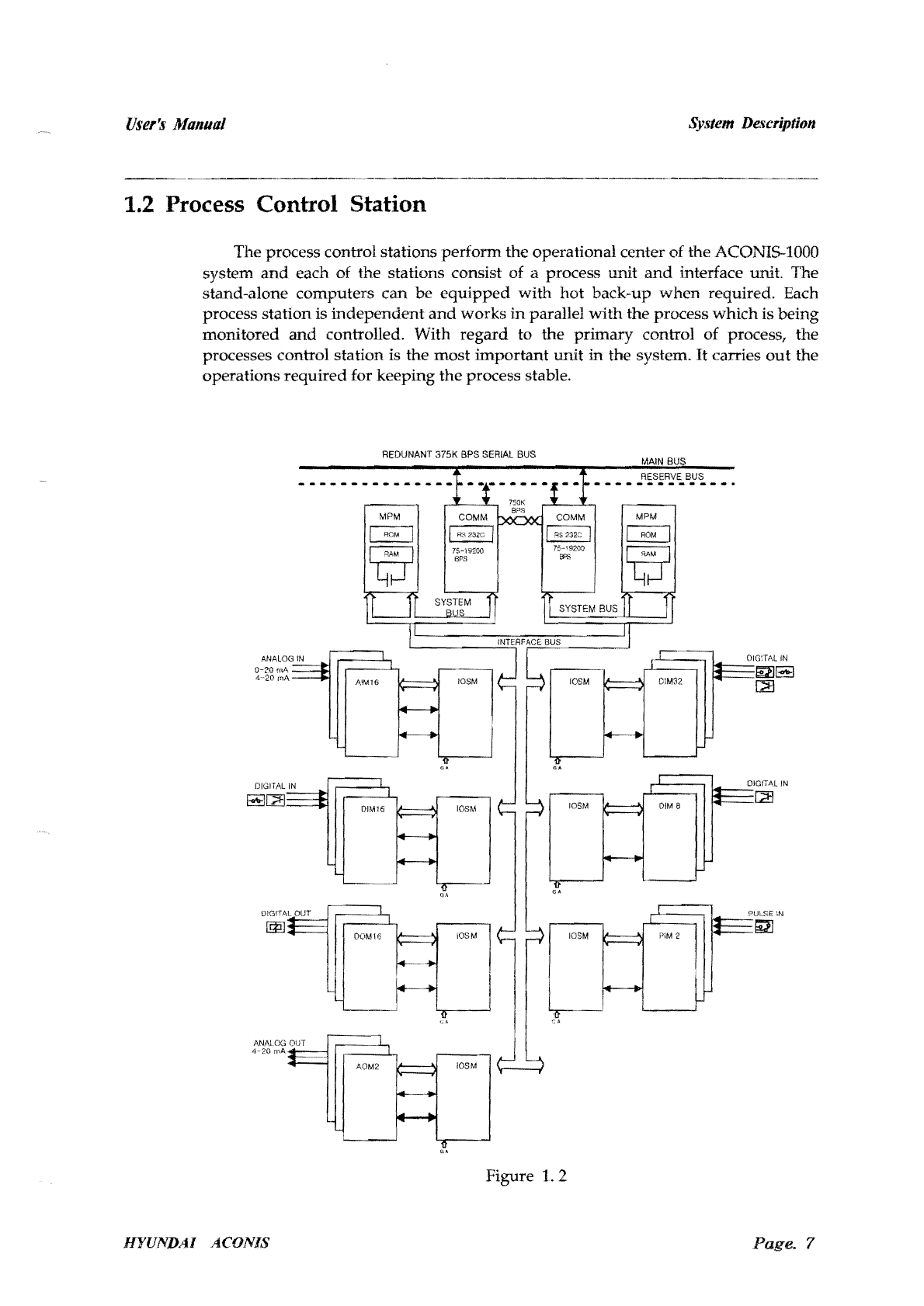
1.2. Process Control Station ............................................................................................·..........·
....
··
....····7
1.2.1. Process
unit
.....................................................................
···
..
·
..
·
..
·····
..
··
......
···
..
····
..
·
..
·
..
··..
·
..
·····
..
······8
1.2.2. Interface unit .................................................................................................................................. 8
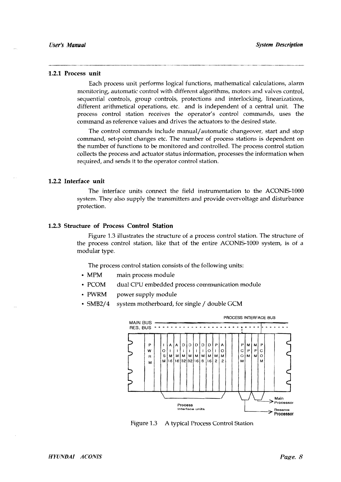
1.2.3. Structure of Process Control Station ....................................................................................... 8
1.3. Server Control Station ........................................................................................................................ 9
1.3.1.
Hardware
Structure
of
Server control Station ....
··
..
·
..
·........·
....
·
..
·
..
·....·
..
···
................·......·
..
10
1.4. Miniature Remote Terminal Unit
and
Real-Time Control Station ·......·
..
·
....
·......·......·....·
..
·
..
11
1.4.1.
Hardware
Structure .............................................................................
··
..
······....·....·····..........
··
..
·11
1.5. Operator Control Stations .....................................................................·····
..
·····
..
···
..
········
..
··
..
····
..
·
..
·12
1.5.1. Video Client .................................................................................
··
..
··
..
·
..
·
..
··
..
··
......·
..··
....
··
..
·
..
··
..
··12
1.5.1.].
Hardware
Structure
of
Video Client
··
....·
..
·....···
..··..··
....·
..
···
..........·......·....····......·
..
·
..
·12
15.1.2.
Display Structure of Video Client ......·
..
·..........····........................·......·......
··
............·...... 13
1.5.2. Alarm Server ..............................................................................................·....·
..
·........·
..
·
..
·
..
·......·14
1.5.2.1.
Hardware
Structure of Alarm Server ·....·
..
···
..
·........
··
......
··
..
·
..
·
....
·
..
·
....
·......................·
..
·14
1.5.2.2. Alarm Printing ........................................................................·····..........
··..··
....
···
..
·····
....
···
..
14
1.5.2.3. Log Printing .........................................................................
··..
·
..
·
..
······........·······
..
·....······
..
·15
1.5.2.4. EAS Management ...............................................................········
..
·
..
··········
..
·····
..
·········
....
···16
1.5.3. Operator Control Station's Communication ....
··
..
·............·......·
..
·
....
·......·......
··..
·........·........·17
1.6. Communication Interface Gateway ....·
....
··
....
·
....
·
....
·
....
··
..........
··
..
·......
·18
1..6.1.
l1ardware structure ...................................................................
···
..
·
..··
..
····....···············
..
··········
..
18
Page. 2
HYUNDAI
ACONIS

User's
Manual
System Description
------
....
-----~------------------------------
.....
---
.....
----
1. System Description
The ACONI5-1000 System is a total control
system
which
interfaces
with
other
multi-functional
alarm
monitoring,
data
acquisition, control
system
and
other
system for ships
and
offshore vessels
based
on
fully distributed microprocessor
technology
in
uniform
hardware
concept. With its
modular
system
structure;
the
system offers a
high
degree of reliability
and
flexibility,
which
makes
it
suitable for
large variety of different
types
and
sizes of ships
where
efficiency
and
reliability are
highly significant.
It
is
adaptable
for all types
of
ships, e.g.
bulk
carriers, cruise
vessels, container ships, reefers
and
other
special
purpose
vessels.
1.1 Introduction
The ACONI5-1000 System
has
a
modular
and
flexible
system
structure,
with
computer
capacity
which
is fully
distributed
to all control
room
stations,
by
use
of
a
microprocessor technology. The tasks
in
the ACONI5-1000 System
are
distributed
among
sub-stations.
The
sub-stations
are
divided
into three
groups:
• Process control station : performs interface
with
process, signal manipulation,
automatic regulation
and
control.
•
Operator
control
station:
performs
control
and
supervision.
• Server control station : control the communication
between
the
other
stations
and
transverse
communication
between buses
and
manage
all
database
over
operator
control stations
and
interface gateway(if GW)
and
other
systems
connected to communication bus.
The controlling
module
of
a sub-station comprises
one
32bit microprocessor
equipped
with
memory
device
and
communication
module.
The
abbreviation
GCM
(General Control Module) is
used
for this controlling module.
Communication
between
sub-stations are carried
out
in
a digital serial
mode
through
a
dual
bus-system
at
the
high
speed
of
375,000 bps, giving the system
an
updating
time
of
less
than
1 second. The communication
media
uses
twisted
pair
cable
as
well as coaxial cable. The
bus
system of the ACONIS-l000 eliminates the
risk
of
total break
down
of the
system
caused
by
earth
failure, electro-magnetic
interference
or
a
broken
bus.
Process control stations are connected
with
one
another
by a
duplexed
process
control
bus
system,
through
the first
synchronous
interface channel of the
communication
module
and
its
stand-by
module. A
maximum
of
32 process control
stations
can
be connected
on
a
bus
system. The
operator
control
bus
system
from
the
operator
control stations is connected
to
the
second
synchronous
interface
channel
of
the serial communication module. This
bus
system
connects a
maximum
of
64
operator
control station
and
one
alarm
station
with
one
another.
The ACONIS-1000 System is
designed
to
meet
the classification of society's
requirements for a periodically
unmanned
engine
room
operation.
The
design
Page.
3
HYllNDAI
ACONIS

lffer~f
Manual
System Description
conforms
to
all rules
and
regulations,
and
all types of
module
are
approved.
In
addition, the ACONI5-1000 System
has
high
reliability
in
their systems.
1.1.1 Features
The ACONI5-1000
alarm
monitoring
and
control system is a
microprocessor-based
system
designed
to
provide
the
ship's
officers
with
all
the
basic
alarm
and
status information they require to
maintain
a safe
and
efficient
operation
of
the
machinery, especially
when
unmanned.
The ACONIS-l000 System
has
the
advantage
that its
structure
is designed
by
the DCS (Distributed Control System),
and
each auxiliary storage device
in
the
microprocessor-based stations
has
Flash Disk
or
ROM (Read
Only
Memory)-based
design. The
structure
of the DCS
has
merit, unlike
the
Central Control System, all
local control stations
can
operate
their
own
local
work
control.
Though
a
supervisory
control station's
break-down
could
occur, the sequential control
works
can
keep
the
entire control process of
the
system
from
stopping
because of
the
supervisory
control station's break-down. The auxiliary storage device is a
memory
space
in
which
executable
code
and
data
can
be
stored
in
the microprocessor-based
system,
and
disk storage
can
be
used
for general purposes.
1.1.2 Installation
Each ACONI5-1000 station
has
the
potential of
both
central installation
and
local installation. Each
unit
can
be
installed locally
and
also all the
units
together
can
be
installed
in
one
cabinet.
1.1.3 Man-Machine Interface
Operator
control stations
provide
full colored graphic displays, functional
keyboard
and
tracker-ball.
Graphic
user
interface
in
the man-machine interface
provides
standard
and
customized
mimics
through
colored graphic display,
and
for
each display
including
the
graphic interface button,
the
functional
keyboard
can
be
directly
handled
by
the
tracker balL
1.1.4 Communication Bus System
The communication
bus
system
of ACONIS-l000
has
a basic
dual
network
structure
in
which
the
lower
bus
system
and
the
upper
bus
system
are
separate,
and
can
work
in
case
of
a
communication
line fault
and
break-down
of
communication
devices
and
stations. The Server control station is
the
communication
master
station
in
the
bus
system
which
connects the
lower
bus
system
and
the
upper
bus
system
and
supervises
and
controls
communication
load
in
the ACONIS-l000 system. The
Server control station is basically a
dual
station consisting
of
the
main
link station
and
the
reserve link station. The reserve Server control station
has
a fault tolerance
by
providing
hot
back-up
of
data
base
in
the
main
Server control station.
1.1.5
Unmanned
Monitoring
All
monitoring
and
alarm
facilities are
provided
both
in
the machinery space
and
in
the
Engine Control Room (ECR). Sufficient facilities
are
also
provided
for
machinery watch
on
the bridge,
and
a watch-caning
subsystem
which
enables
Page.
4
I1YUNDAI
ACONIS

User',,)
Manual System Description
engineers to be automatically called to the ECR
when
they are away
on
watch-call
duty
in
their quarters. Thus, both the machinery
and
the ECR
may
safely be left
unmanned
while machinery
watch
is carried
out
on
the bridge.
Page. 5
HYUNDAI
ACONIS

User's Manual System Description
1.1.6
System
Structure
rD."
····101
......
.
~ LJ
~J
l~>
·."tb~~~,~~n
fl6a..
~.··
..
~·-.e
..
..
~~
-~~
..
___l
t..b".
CTIJ
HYUNDAI ACONIS
Page.
6

User's
Manual
System
De,~cription
1.2 Process Control Station
The process control stations
perform
the operational center
of
the ACONIS-1000
system
and
each of the stations consist of a process unit
and
interface unit. The
stand-alone
computers
can
be
equipped
with
hot
back-up
when
required. Each
process station is
independent
and
works
in
parallel
with
the process
which
is
being
monitored
and
controlled. With
regard
to
the
primary
control of process, the
processes control station is the
most
important
unit
in
the system. It carries
out
the
operations
required
for keeping
the
process stable.
0-20
rnA
4--20
inA
DIGITAL
IN
~G!l
DOM16
REDUNANT
375K
BPS
SERIAL
BUS
MAIN
BUS
RESERVE
BUS
------------.-
I
'"'"
~.-
MPM
OIG:TAL
IN
~~
[2J
PUL.SE IN
till
AOM2
Figure
1.2
HfUNDAI
ACONIS
Page.
7

User's
Manual System Description
1.2.1 Process
unit
Each process
unit
performs logical functions, mathematical calculations,
alarm
monitoring, automatic control
with
different algorithms, motors
and
valves controL
sequential controls,
group
controls, protections
and
interlocking, linearizations,
different arithmetical operations, etc.
and
is
independent
of a central unit. The
process control station receives
the
operator's
control commands, uses the
command
as
reference values
and
drives the actuators
to
the desired state.
The control
commands
include
manualj
automatic changeover,
start
and
stop
command,
set-point changes etc. The
number
of
process stations is
dependent
on
the
number
of functions to
be
monitored
and
controlled. The process control station
collects
the
process
and
actuator
status
information, processes the information
when
required,
and
sends
it
to
the operator control station.
1.2.2 Interface
unit
The interface units connect
the
field instrumentation to
the
ACONIS-IOOO
system. They also
supply
the transmitters
and
provide
overvoltage
and
disturbance
protection.
1.2.3 Structure
of
Process Control
Station
Figure 1.3 illustrates
the
structure
of a process control station. The structure of
the
process control station, like that
of
the entire ACONIS-1000 system, is
of
a
modular
type.
The process control station consists of
the
following units:
• MPM
main
process
module
• PCOM
dual
CPU
embedded
process communication
module
• PWRM
power
supply
module
•
5MB2/4
system motherboard, for single / double
GeM
PROCESS INTERFACE BUS
MAIN BUS
RES.
BUS
- • - - - - - - - -
••
- -
••••
-
••
! . - - -
1-
. - . - - .
~
I
~
P
W
RI
!
I M I
I
0
S
M
AlA
D
~I~
~
16116132
D
I
M
32
D
I
M
16
D D
11
0
M M
8
16
!
P
I
M
2
A
0
M
2 I
P M
C P
o M
1M
M P
P C
M
~I
yv
Main
-7'
Process
or
Process
Interface
units
Reserve
~
Prooessor
Figure 1.3 A typical Process Control Station
HYUNDAI ACONIS
Page.
8

User's
Manual
System Description
The following types of interface units can be used at the process
control stations;
•
105M
input-output
scanning
module
multiplexers for the process interface units
• AIM16 analog
input
module
for 16 analog signals
• DIM32 digital
input
module
for
32
contacts
• DIM8 digital
input
module
for 8 contacts,
e.
g. 3 line
input
with
33k
.Q
for monitoring of auxiliary engine
shutdown
• DIM16 digital
input
module
for 16 contacts
• DOM16 digital
output
module
for 16 contacts
• PIM2 pulse
input
module for a signal pulse frequency
• AOM2 analog
output
module
for 2 analog
output
signals
• DOD
demand
on
display
1.3 Server control Station
The Server control station controls
and
supervises the data communication
between the stations connected to the process control
bus
and
operator control bus.
Data transfer at theServer control station is serial. The HDLC protocol is
used
in
the
communications.
The Server control station
manages
the communication
bus
system
in
the
ACONIS-l000 system
and
functions as
an
information server for the operator
control stations, has the features to get
I/O
data
in
the lower
part
and
alarm
information for the process control station,
and
has the task
of
synchronous
function.
In
addition, the database is installed inside, all
the
work
such as creating a
new
event
in accordance to
I/O
data
status,
and
managing information
in
system,
log information,
trend
information,
alarm
display list
and
inhibit display list,
and
a
systemclock are carried out.
The Server control station is a
dual
station designed
by
the
structure of fault
tolerance. The operator control
bus
and
the process control
bus
are designed
by
the
dual
network
and
each
bus
is isolated
and
connected to the Server control station.
Therefore if a break-downoccurs
in
one system, it
won't
effect the other systems.
Because a
bus
system is designed
by
the
dual
network,
when
one
network
has
a
problem,
it
is automatically replaced
by
the reserve
network
in the Server control
station.
During
this process, delay
and
loss of
data
in
the
network
requiring
replacement never occurs. In
main/reserve
substitution, the operator control
bus
is
dependent
of the Server control station,
and
the process control station
bus
is
independent
of the Server control station. Therefore, the operator control
bus
is
connected to
the
main
bus
system
in
the
main
Server control station,
and
to the
reserve
bus
system in the reserve Server control station. Irrespective
of
this, the
process control
bus
is simultaneously connected to the
main/
reserve system.
The most
important
feature is
the
consistency of each database installed inside
in
case of a
main/reserve
substitution
in
the Server control station. This is because
Page. 9
HYUNDAI
ACONIS

User's Manual System Description
.--~.-----------.---~--------~
the reserve Server control station must hot back-up the database in the main
Server control station under the suspend mode. The main Server control station in
the beginning of operating back-up the data base in the reserve Server control
station for about 3 minutes when the reserve Server control station is active, and
when completed, the back-up communication right is given from the reserve
Server control station.
The following
show
the connecting
methods
of
main/
reserve Server control
stations,
operator
control
bus,
and
process control bus.
1.3.1
Hardware
Structure
of
Server control Station
The
Servercontrol
station
consists
of
the
following units:
•
MPM
IV 32-bit microprocessor-based
main
processing
module
(2
ea.)
• FDC full
display
controller
and
ROM-Disk, Fresh Disk
(2
ea.)
•
COMM
II
dual
CPU
embedded
communication
module
(2
ea.)
• PWRM
power
module
(2ea.)
Figure 1.3 illustrates
the
structure
of
the
Server control
station
VIDEO
GENERATOR
. .
1
•••
_.
_________
•
_____
_
._,~-_-._.---_-_----.---
M.
BUS
••••••••
(]
(]
C
C
SERVER
CONTROL
STATION
R.
BUS
MAIN
~
" J ' , f
'0
I,j......
loOU
.'
3>
~,
...
PROCESS PROCESS
STATION STATION
Figure
1.3 Typical
structure
of process, server,
video
generator
HYUNDAI
ACONIS
Page.
10

User's Manual System Description
1.4 Miniature Remote Terminal Unit and
Real-Time Control Station
In
order
to identify operation status of electrical equipment, Miniature Remote
Terminal Unit gets information
through
various
Input
Card
to obtain value
or
status
of sensor,
and
performs
command
of operation to drive certain device. The system
typically takes
in
charge of PID control. Moreover,
it
is
used
for data collection at
remote distance, if necessary. Direct installation of this system to
yard
may
eliminate malfunction
and
reduce signal lines.
And
Real-Time Control Station helps MRTUs to communicate MRTU's data to
Server
and
vice-versa.
It
acts as supervisor of connected MRTUs
with
initializing
MRTUs
and
PID parameter tuning.
It
communicates
with
MRTU
through
ARCNET
and
with
Server
through
RS-48S.
1.4.1
Hardware
Structure
This Stationconsists of the following units:
a) Real-Time Control Station
• MPM4C micro-processor based
main
processing
module
• DCCM
dual
CPU
embedded
process communication
module
• UCPWR
power
supply
module
b) Miniature Remote Terminal Unit:
• MCPU
main
process
module
• MIDO digital
input
/
output
module
• MAl analog
input
module
• MAO analog
output
module
• MPOWER
power
supply
module
Page.
11
HYUNDAI ACONIS

User~f;
Manual System Description
Figure1.4 illustrates
the
structure
of
the
station
SYSTEM
SERVER
STATION
i
0
0
V M
C P
p M
w 4
R C
0
0
C
C
M
0
ARCNET
1.2SMbps
Real-Time
Control Station
t I
,,'
--MA5(:'i6E'"
..
A
M
p
0
W
E
R
. .
M
P
C
U
M
D
I
0
M
A
I
M
A
0
>
>
>
>
M
P
0
w
E
R
M
P
c
u
M
D
I
0
M
A
I
M
A
0
~
(
C
C
..
Mlnuature Remote TermInal MIniature Remote Terminal
Unit
Unit
Figure1.4 A typical
structure
ofRTCS, MRTU
1.5 Operator Control Stations
Operator
control stations
in
the
ACONIS-1000 system transfer
the
useful
information
to
the
operator
through
Graphic user interface
or
man-machine
interface,
and
receive
the
operator's
signal
through
input
apparatus,
and
during
this
time
the
video generators
and
the
alarm
station
work
by
the
operator's intention.
1.5.1 Video
Oient
The
video
client
output
the
process
data
to
the
monitors
via
a full-graphic
display controller. The
video
client picks
up
the
necessary process
data
from
the
operator control
bus
and
displays the
data
with
the
display format selected from
the
functional
keyboard
or
tracker ball.
1.5.1.1 Hardware Structure of Video Client
The
video
client is connected to
the
operator control
bus
through
a
communication module.
It
consists
of
the
follOwing units:
• MPM N 32-bit micro-processor based
main
processing
module
• FDC full display controller
and
ROM-Disk, Fresh-Disk
•
COMM
II
dual
CPU
embedded
communication module
HYUNDAI
ACONIS
Page,
12

User's
Manual
System
Description
Figure 1.5
shows
the structure of
the
video
generator
20" COLOR CRT
~
t:::::::::::l
[::=J
c::::::::J
I:=:J
=
=
===:J
I:=:J
c::::::=
I:=:J
= KEYBOARD
t::::=:Jc::::::::J~C::::::==c::::::::J
t:::::::::::lc::::::::Jt:::::::::::lc::::::==c::::::::J
TRACK-BALL
o
ACONIS
GJJ~~TOR
ON
OFF
~
Fo
e
COMMU
~
o
~
HYUNOAI
R.BUS
M.BUS
Figure 1.5 The Structure of Video Generator
1.5.1.2 Display Structure
of
Video
C
lient
The basic
arrangement
of the video client display
on
screen are as follows
• Status Display
•
Group
Display
•
Alarm
Display
• Inhibit Display
•
Pow
er Control Display (optional)
• Graphic Display (optional)
• Trend Display
• Log Display
•
Custom
Display
•
Help
Display
The text
and
the graphic symbols are
supplied
through
the
relevant color
data
in
the condition of
the
channel of
the
display of the video client. The color
data
used
are as follows :
GREEN
Normal
Status
RED Acknowledged
Alarm
Status
RED BLINKING Unacknowledged
Alarm
Status
CYAN Interlock Status
PURPLE Suppressed Status
HYUNDAI
ACONIS
Page
.
13

User's Manual System Descrip
ti
on
1.5.2
Alarm
Server
The alarm server
has
the capability to
output
the
status
events from the
ACONIS-1000 system
in
chronological
order
through
the alarm printer, to timely
output
the normal log information
and
the daily log information by the log printer,
and
to
manage
EAS (Extended
Alarm
System).
1.5.2.1
Hardware
Structure
of
Al
ar
m
Server
The alarm server consists of the follOwing units:
• MPM IV 32-bit micro-processor based m
ain
processing
mo
dul
e
• FDC
•
COMMll
•
105M
• DIM16
• DOM16
full display controller
and
ROM-Disk, Fresh-Disk
dual
CPU
embedded
communication
module
16bit
input-output
scanning
module
16 digital
input
module
16 digital
output
mo
dul
e
(2
ea.)
EC
R W!H
ENG
I
NEER
RS485
COMMUNICATION
ALARM
PRINTER
A
LARM
SE
VE
R
= =
LOG
PRINTER
<=>
RBUS
M.BUS
1.5.2.2
Alarm
Printin
g
The alarm
printing
is allegedly
wanted
to
prin
t o
ut
the
events from
the
system
in
chronological order. The events are
th
e al
arm
event,
the
normal
event,
an
d
th
e
inter-lock event. The color
prints
are
red,
blue
an
d block for alarm event, inter-lock
e
vent
and
normal
event
respective!.
HYVNDAl
ACONIS
P
age.
14

User's Manual System Description
The
following is
an
example of a
print
out
form of the
alarm
event.
H
YUN
D
AI
Ae
O
NIS
SY
STeM MAR
IN
E & OFFSHORE
c
~
.
_ :
••
__
""":::"""
~~
~~L~~~M
!=
Y
:
E..
~l
f'J:.
1
!:J
!!
t:!
9
__
__.
____
=,
(H
\'UND.A.I
ACO
I~18
.ALARM
8Y:3TEMJ·.·········.·
..
·-·--·-
·-
··-·-·····-
---
·--··-····[
PAGE
0000 1J
98/03/15
22:36~
3S
1111
MfE
SHI
'DOW~I
SHD
AI..
3Wo.:-v'
15 22'36:j5
1112
MiE
SLOVVDQWf'; 3LtJ ,
I\,l
98/W
15
2~:3~:
J5
11
1
3,11i
E
\,IVnODI'V.I!.RD
,),)\( C(lNT 8.,.8
XlI
2
AL
98/0311<;
22:36:
3'J
1115
MIE
SAFEW
BY:: PWR
FJI.IL
'
)(j\
2
P.
9
B/03!15
2236:35
1116
WRC.IJG
V\I.AY
YA
~
,;I.L
SalO3/
15
Z?:36:35
II~<I
WE
SIIFET'"
AlP
PRESS
P~L
" AL
SatWl5
2Z
~G:
35
1
125
WE
EXH
VV
SPR
.'IIR PRESS
PAL
.J
AI
.
9!Y03!15 :2.36.35 I
IZE>
MIE
C('NTSYS
ELE':
F'INR
FAIL
Xl\,
.~
Al
98/(13/
15
22:36'
3'"
1131
!vi
lE
tJ':,
1 AU' BLOWER p
B~J
X"
. Z AL
SW03/15
::'Z.36:
35
II
·2
MiE
t
10
J
ALJ,~
8L.)VVER
ABt4
XlI.
ilL
98/G3/t5
22:36:35
11
41
CPP
RE"" :ncc
ot.n
SYS
F.'\IL y
....
:?
Al
813!()3/t
5
22:36:35
1142
CPP
leu
F",n,fR
F.
'\ll
,A,L
' -
11
,
1.5.2.3
Log
P
rinting
The Log
printing
is the
method
of
printing
out
the
normal
log information
and
daily log information
by
the
log
printer. In general, all the
printing
of
the
log
information is carried
out
at
different time period,
but
when
the
normal
log
information
and
daily
log
information are
printed
out
at
the
same
time,
the
printing
of the daily log information is followed by
that
of the
normal
log information, as
the
priority of
printing
is given to the daily log information.
The
following is
an
example of a
print
out
form
of the
alarm
event.
SHIP . HYUNDAI
MERCHANT
MAR
IN
E H1902 HYUNDAI
ACO
NI
S SYSTEM
LOGGING TIME : 1998/03/2023:00
:00
«NO
RMAL LOG REPOR
T»
Pg# 19980320·23·01
ch#
A'
Description
Range
LH
r,!lax.
LL
Min. CV
Average
Inst.eod
e
liS
E
Satus
1141
CPP REMOTE COj\JT SYS FAIL
XA
1142
CPP ICU
PVlJR
FAIL
XA
2
.A.LA.RM
1143
CPP
RCCU
ILLPWR
FAIL
XA
2
.ALARM
1144
CPP HYD RTN OIL FILT
F.A.lL
Xf'..
2
AU\RM
1145
CPP RPM
TRANS
FAIL
XA
2 ALARM
1146
CPP BACK-UP SYS FAIL
XA
2
foUR!,)!
1147
cpp
HYD
SST
SACK-UP 'liN F
XA
2
,A,LARM
1148
CPP
HYO
PROP
VN
FAIL
XA
2
ALAR!'."
1321
MJE
AIR
COLER
CFW
IN P 6.00 2.09 SfF PIAL 2
ALA.RM
A
0.00·6
.00 0.00 0 0.
00
KGJCM2
1
322
MfE AIR
COLER
CFW
OUTT
150
75
SJF
TIAH 2
ALARM
A
0-150
0 0 0 DEG/C
1323 MAIN
CSWPUMP
OUTTEMP
6.8
--50.0 S/F TIAH 3
AL~RM
A -50.
0·50
.0 -50 -50.0 -50 DEGJC
1324
MAIN
CBVV
PUMP
DISCH
PRESS
3.34
0.00
SJF
PIAL 2
JI.L).,RM
HYUNDAI
ACONIS
Page.
15

User's
Manual
System Description
The following is example of a print out form of the daily log.
SHIP .
HY
IJNUAI
ME.RCH
.
ANT
MARINE
HI
902
L
OG
GIN 11M •
1998/03/2020:
0:00
CHI
A
1141
1142
1143
1144
1145
1146
1147
1148
1321
A
1322
t-.
1323
A
1324
A
Description
CPP REMOTE
CO~4T
SYS Ft-JL
CPP
leu
PWR
FAIL
CPP RCCU
ILL
PWR
FAIL
CPP
HYD
RTM OIL FILT FAIL
CPP RPM TRANS FAIL
cPP
BACK-UP
SY8
FAIL
CPP
HYD
BST BACK-UP
"IN
FAIL
CPP
HYD
PROP
Y!V
FAIL
M/ E
AIR
COLER CFW
IN
P
0.00 -6.00
M/E
AIR
COLER OFW OUT T
0-150
Mt-,IN CSW PUMP OUT
TEMP
A-50 -
50
MAIN CSW PUMP DISCH PRESS
0.00 -4,00
« DAILY
LOG
RFPORT» HYUNDAI ACONIS
SY
S
TEM
PQ~
1898 320-
2G
01
-
08:00 12:00
Ins.co
E
unit
NORrvlAL I ._ : .1 XA 2
NORMAL r 1 x A 2
~JORMAL
,
XA
2
NORM.6
.L
IJ'
, XA 2
NORMAL , . x
t-o
2
NORMAL
><A
2
NORM.I>.L
1
xt-o
2
NORMt-,L " .1 X
.6.
2
J PIAL 2
KG/C
M5
r·
TIAH 2
DEG/
C
TI
3
DEG
/C
Plt-.L 2
KG/e
M5
16:00
Ma
x.
l,I
0.00
0
-50,0
0,
00
20:00
Min.
0.
00
0
-50,0
0,
00
04:00
. 1
i 1
0.00
0
-50,0
I'
0,00
1.5.2.4 EAS
management
The EAS (Extended
alarm
system)
has
a function to enlarge the scope of the
alarm
event
occurring inside the system
when
necessary, to recognize
the
alarm
occurring
in
other
areas
outside
ECR
and
to
unman
the
alarm monitoring. The
basic function of the EAS is
not
only
the
extension of the alarm,
but
also
the
duty
transfer, engineer caller,
and
re-alarm.
I
ECR
II • I W/H
~
• IE
NG
INEER
•
RS485
COMMUNICATION
HYUNDAl
ACONIS
Page. 16

User's Manual System Description
1.5.3
Operator
Control
Station's
Com
mun
ication
The
connecting
method
of
the
COMM
II,
intercommunication
module
of
the
video
generator
and
the
operator
control
bus
are
as follows.
•
CONI
connect to
main
operator
control
bus
• CON2
not
connect
• CON3 connect to
reserve
operator
control
bus
• CON4
not
connect
In the
connection
of the
video
client
and
operator
control bus, COMM II
automatically recognizes
the
present
bus, receives
information
on
the
Server
control
station
through
the active
operator
control
bus
automatically
installed,
and
transfers
data
input
from user. Therefore,
in
the
video
client
application
program,.
the
information
of the
present
active
operator
control
bus
is
shown
on
the
upper
left of
the
monitor,
and
in
the
main
ope
r
ator
control
bus
nothing
is
shown
because this is
in
a
condition
of default.
However
, the
message
"RESERVE" is
shown
when
the
reserve
operator
control
bus
is active,
and
when
it is
not
actjve the
message
"RESERVE" blinks continuously. This
means
that
the active
operator
control
bus
is
scanning
to search for the active
bus
,
and
if this
continues
the
operator
control
bus
is
down.
Operator control stations
VID
EO
S
ERVE
R I VIDEO S
ERVE
R 2 VIDEO
SE
RV
ER
3
C
CH2 CH3
CH4
....
MAXI6
,--+-
__
O
_H'-c_
O
,,3
__
0
_CH_'
-,
LI_
?+H_I
__
O_
'--C.._
_
O
;-3
_ _0
_H_'
-,I
[9 o Q 0
COMM
II
COMM"
COMM "I
Ma
ll1
li
ne
1
C
f-I
I
CH
2 CH3 91 Main
9 0 0 Server Control Station! I
i I
~
:CO
MM"
10
O:¢
(:)1
Reserve
Server Control Staion
C
OMM"
F.ese
rYe
li
ric
-Ma
in
Une
C
HI
CH'
CHI
CH2
CM
3
CH
'
o o o o o o
PC
OM
PCOM
Process
control
stations
HYUNDAI
ACONIS
Page.
17

User's Manual System Description
1.6
Hetero-homogeneous
communication
Interface
Gateway
(ifGW)
This
out
communication
ACONIS-IOOO
and
other system
has
different protocol
and
monitoring function for
ACONIS-IOOO
;';'l<UP'Tl
for """f"Olrri etc.
and
IPX
protocol
equipped
on
vessel is
between
1.6.1
Hardware
structure
It
consists of the following units:
..
MPM
IV
full controller
with
LAN
communication
module
..
FDC
..
COMMII communication
module
SHIP NETWORK
o~
OFF
1------1
6 HYUNDAl
R.BUS
M.BUS
1.6
The
""t-'rI1C't-I1'1"t:>
of
Interface
Gateway
HYUNDAI
ACONlS
18

UJer'J
Manual
Operating Information
ACONIS-l000
Operating Information
Hyundai
Heavy
Industries Co., Ltd.
HYl1NDAI
ACOiVNo,'
Page.
1
Table of contents