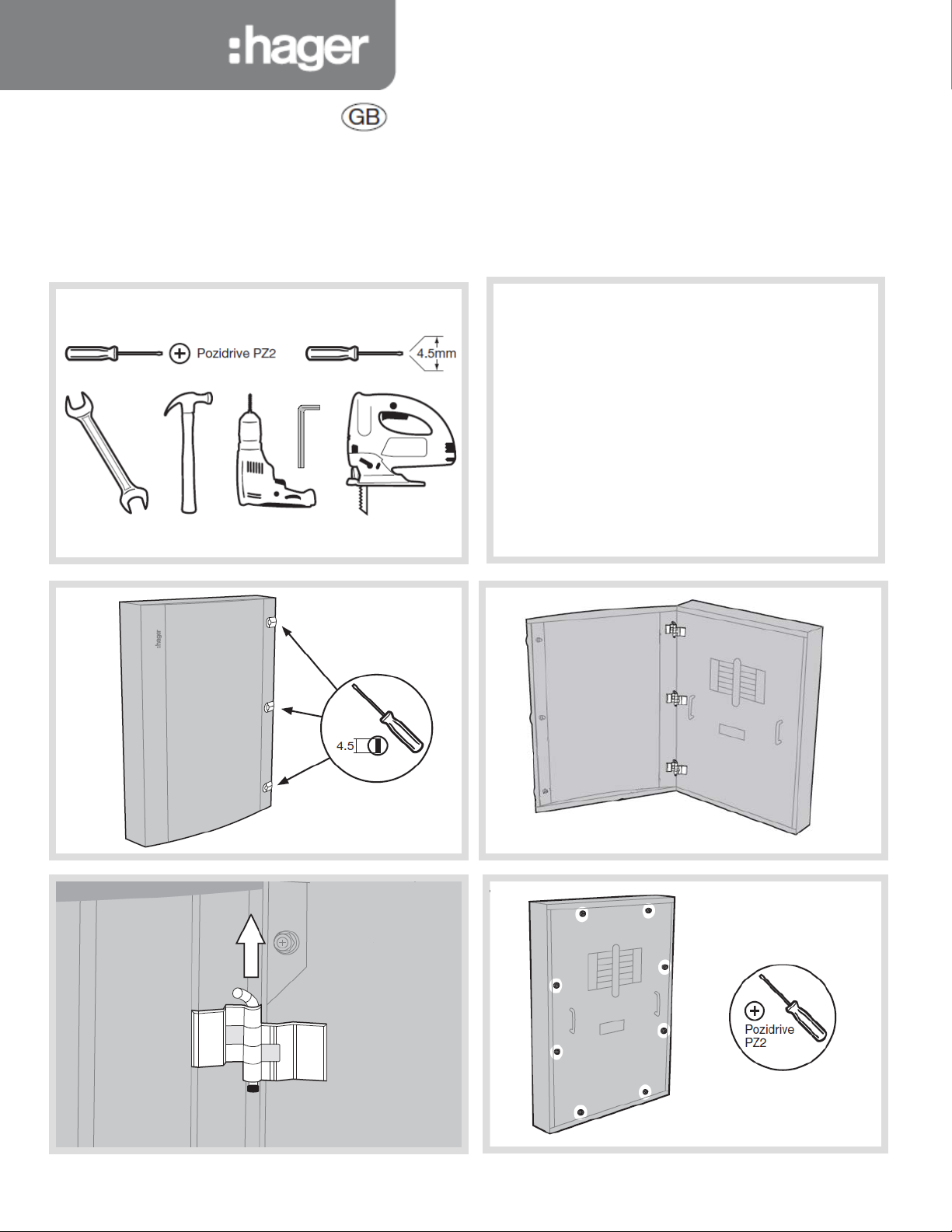
hager Invicta 3 JF8 B Series User manual

Installation instructions
Notice d’instructions
Bedienungsanleitung
Instrucciones de uso
Instruções
Bruksanvisning
Gebruiksaanwijzing
JF8**B(G)
JF6**B(G)
Invicta 3 Panelboard
All product(s) must be installed by a suitably competent
electrician giving consideration to their intended use and in
accordance with the current edition of BS 7671 (IET Wiring
Regulations).
The Electricity at Work regulations and the Health and Safety at
Work Act shall be complied with.
Only equipment and arrangements specified in Hager’s technical
documentation / catalogue shall be used
Install inthe vertical plane only with the recommendation to use a
cable extension box below the incomer to allow ease of cabling.
Notice:
To prevent potential overheating from loose connections the
installer shall check connections are tightened to the torque levels
stated in these instructions prior to energising this board. This
check should include factory made connections which may have
loosened in transit or as a result of.
ZD0741 Issue 6

Fixing points with central keyhole
ZD0741 Issue 6

400A Incomer kits contain:
•3 x Phase extensionlinks
•3 x spreader links
•6 x Phase link Allen fixing bolts and washers (M10)
•4 xLong fixing screws
•1x MCCB
•3 x M10 Bolts
•Terminal covers
Ensure terminal shrouds are
removed before fitting.
JF6/8 3 Pole h 400A MCCB incomer kit
1
2
Connect the extension links to the busbar with the 3 x M10
coach bolts. Hand tighten at this stage.
Now tighten the MCCB fixing screws to secure the MCCB to
the pan assembly.
Once the MCCB is in place tighten all M10 electrical
connections to 22Nm
Fit the terminal shrouds
17 mm A/F
8 mm HEX
A
B
ZD0741 Issue 6

400A Incomer kits contain:
•3 x Phase extensionlinks (per Phase)
•2 x Neutral links (doubled up - 4 Pole only)
•4x spreader links
•6 x Phase link Allen fixing bolts and washers (M10)
•4 xLong fixing screws
•1x MCCB
•3 x M10 Bolts
•Terminal covers
Ensure terminal shrouds are
removed before fitting.
JF6/8 3&4Pole P 400A Electronic MCCB incomer kit JF843P4 & JF844P4
Fit the MCCB to the pan assembly with the fixings provided
Fit the spreader links to the bottom of the |MCCB with the
fixings Connect the extension links to the busbar with the 3
xM10 coach bolts.
Hand tighten at this stage.
Now tighten the MCCB fixing screws to secure the MCCB to
the pan assembly.
Once the MCCB is in place tighten all M10 electrical
connections to 18Nm
ZD0741 Issue 6
Remove the busbar shield.
Prepare the Phase links as shown (3 per Phase)
2 off Neutral links doubled up if 4 pole
Fit the terminal shrouds
JF844P4 Shown for illustration
Fit the MCCB to the
pan assembly with
the fixing screws

630A Incomer kits contain:
•3 x Phase extension links
•3 x spreader links
•6 x Phase link Allen fixing bolts and washers (M10)
•4 xLong fixing screws
•1x MCCB
•3 x M10 Bolts
•Terminal covers
Ensure terminal shrouds are
removed before fitting.
Connect the extension links to the busbar with the 3 x
M10 coach bolts. Hand tighten at this stage.
Now tighten the MCCB fixing screws to secure the MCCB
to the pan assembly.
Once the MCCB is in place tighten all M10 electrical
connections to 22Nm and M12 to 45-65Nm
Fit the terminal shrouds
17mm & 19 mm
A/F
JF6/8 3 Pole h 630A MCCB incomer kit
2
Fit the MCCB to the
pan assembly with
the fixing screws
Fit the extension
links (A) to the
MCCB with the Allan
fixings
ZD0741 Issue 6

630A 4 pole incomer kits contain:
•3 x Line extension links
•2x Neutral links
•4 x spreader links
•8 x Phase link Allen fixing bolts and washers (M10)
•4 xLong fixing screws
•1x MCCB
•4 xM10 Bolts
•Terminal covers
Ensure terminal shrouds are
removed before fitting.
JF6/8 4 Pole h 630A MCCB incomer kit
Connect the extension links to the busbar with the 3 x M10
coach bolts the M8 coach bolts. Hand tighten at this stage.
Connect the 2 neutral linkswith the M8 coach bolts, making
sure they are fitted under the Neutral phase of the MCCB.
Hand tighten at this stage.
Now tighten the MCCB fixing screws to secure the MCCB to
the pan assembly.
Once the MCCB isin place tighten allM10 electrical
connections to22Nm and M12 to 45-65Nm. Tighten all M8
connections to 13Nm. Fit the terminal shrouds
Remove the busbar shield.
Fit the MCCB to the pan assembly with the fixings provided
13mm, 17mm &19 mm
A/F
ZD0741 Issue 6

630A 4 pole incomer kits contain:
•3 xLine extension links
•2x Neutral links
•8 xPhase link fixing bolts and washers (M12)
•4 xLong M6 fixing screws and washers
•1x 630A switch
•1 xrear terminal shield
•Terminal covers
Ensure terminal shrouds are
removed before fitting.
JF6/8 4 Pole 630A Switch disconector incomer kit
Remove busbar cover and fit the switch to the pan assembly
with the M6 fixings provided
Fit the rear terminal shield (A)
Connect the extension links to the busbar with the 3 x M10
coach bolts. Hand tighten at this stage.
Connect the neutral linkswith the M8 bolts. Hand tighten at
this stage
Now tighten the M6 fixing screws to secure the switch to the
pan assembly.
Once the Switch is in place tighten all M10/M12 electrical
connections to22Nm. tighten the M8 electrical connections
to 13Nm. Fit the cover plate tothe front cover.
1
3
2
A
ZD0741 Issue 6

Locate the insulated barrier over the nylon pillars.
Secure used fixings provided
Locate the link sub assembly onto the nylon pillars
Use 3 x M6 bolts and washers to fix the links to the pillars
JF6/8 3 Pole direct connect incomer kit
Direct connect kit includes:
•3 phase link assembly
o3 x nylon pillar
o1 x direct connect strap
o3 x M6 bolt, spring washer, flat washer
o6 x M12 bolt, flat washer, carp nut
o1 x insulation barrier
•Lower direct connection shield
o4 x M6 fixing bolts (for shield
•Front cover adapter plate
Remove busbar shield
Place 3 x nylon pillars and hand tighten
Fit the insulation barrier over the nylon pillar
1
Tighten all M10 electrical connections to 22Nm
Refit the busbar shield
Use the 4 x M6 fixings to fit the lower direct connection
shield
Use the 3 x M10 bolts and washers to fix at busbar
3
2
ZD0741 Issue 6

Fitting Single Pole MCCBs
Single pole MCCB contains:
•2 x Fixing bolts
•2 x Spring washers
•2x Single fixing plates
•2 x Double fixing plates
Mount the MCCB on to the busbar finger with the red trip
button facing inwards. Fix the device to the pan assembly
using the fixings provided
See single pole instructions for more information
Tighten electrical connections to 6Nm
Fitting Three Pole MCCBs
Three pole MCCB contains:
•2 x Fixing bolts
•2 x Spring washers
•2x Flat washers
Mount the MCCB on to the busbar finger with the red trip
button facing inwards. Fix the device to the pan assembly
using the fixings provided.
Use the Auxiliary/Shunt trip accessory channel (▲)to dress
cables from these accessories
See three pole instructions for more information Tighten
electrical connections to 6Nm
Only equipment andarrangements specified in Hager’s technical documentation / catalogue shall be used.
ZD0741 Issue 6
Mount the MCCB on to the busbar finger with the red trip
button facing inwards. Fix the device to the pan assembly
using the fixings provided
See single pole instructions for more information
Tighten electrical connections to 12Nm
Fitting Three Pole P 250 MCCB's
Three pole MCCB contains:
•2 x Fixing bolts
•2 x Spring washers
•2x Flat washers
Mount the MCCB on to the busbar finger by screwing the
allen bolts to the MCCB prior to offering up to the busbar with
the red trip button facing inwards. Fix the device to the pan
assembly using the fixings provided.
Use the Auxiliary/Shunt trip accessory channel (▲)to dress
cables from these accessories
See three pole instructions for more information Tighten
electrical connections to 12Nm
Fitting Three Pole X 250 TM MCCB's
Three pole MCCB contains:
•2 x Fixing bolts
•2 x Spring washers
•2xFlat washers
•3 x Phase bolts

Achieving Form 3b type 2 on x160 frame MCCB outgoing
Using HYA021H Terminal cover: Outgoing Devices x160 Frame only (125A)
Cut Out Dimensions are shown below to achieve IPXXB (Form 3b type 2)
15mm
6mm
2.5mm Cable
4mm Cable
6mm Cable
13mm (complete inner cut-out width)
10mm Cable
&
16mm Cable
15mm
25mm
13mm (complete inner cut-out width)
25mm Cable
&
35mm Cable
Achieving Form 3btype 2 on x250 & P250 frame MCCB outgoing
Using HYB021H (3 Pole) HYB022H (4 Pole)Terminal cover: Outgoing Devices x250 Frame (250A)
Using HYT021H (3 Pole) HYT022H (4 Pole)Terminal cover: Outgoing Devices P250 Frame (250A)
Cut Out Dimensions for the insert are shown below to achieve IPXXB (Form 3b type 2)
ZD0741 Issue 6

Service Conditions
Hager distribution boards must only be fitted with Hager Equipment and
arrangements specified in Hager Technical documents and catalogues.
Indoor Use Only
Pollution degree: 3
Forms of separation: Form 3b when outgoing shrouds are fitted. A
competent person must always complete a risk assessment and appropriate
test to confirm that, the un-shrouded neutral within the Panelboard is not a
hazardous live part. In particular, The Electricity at Work Regulations 1989
including any amendments must be complied with.
Note 1 - or rating of main incomer whichever islower
(Inc)
Diversity/Loading Factor/RDF
0.7
0.6
Performance Characteristics
Panelboard to BS EN 61439-2 (unless stated otherwise)
690V a.c. 50Hz
415V a.c. 50Hz
6kV
(Subject to compliance with relevant regulations in the current edition of BS
7671)
Warranty
This distribution board is offered with a 24 month warranty against defective
material ormanufacture. If a warranty claim isnecessary, please call the
technical support number given at the bottom of the page and we will be
pleased to help.
JF6/JF8 Incomer Kits
JF6/JF8 Accessories
JF003BP
JN001BP
JFPLATE
JF801E
JF801EG
JF803E
JF803EG
JF805DK
JF805E
JF806E
JF806DK
3P BLANKING PLATE 250A FRAME
1P BLANKING PLATE 125A FRAME
JF4 &8ENDPLATE
SMALL DIN RAIL BOX, PLAIN DOOR
SMALL DIN RAIL BOX GLAZED DOOR
LARGE DIN RAIL BOX, PLAIN DOOR
LARGE DIN RAIL BOX, GLAZED DOOR
DOOR KIT FOR SMALL SPREADER BOX
SMALL SPREADER BOX (NO DOOR)
LARGE SPREADER BOX (NO DOOR)
DOOR KIT FOR LARGE SPREADER BOX
ZD0741 Issue 6
JF6/JF8 Surge Protection Kit
JF861SPD Type 1+2 Surge Protection Kit
JF6/JF8 Incoming Meter Kit
JF803MID MID Multifunction Meter Pack
600A 415 a.c. 50Hz
800A 415 a.c. 50Hz
Maximum Current (lnA)
JF6**/JF8** Using outgoing x160 / P250 MCCB
50Hz
TNC-S, TN-S and TT
IK05
Electromagnetic compatibility (EMC) classification EMC Environment B
Metallic Enclosure Class 1
Wall mounted stationary
assembly fixed Ui
Ue
Uimp
Rated Frequency
Suitable earthing system
Mechanical Impact Protection
Type F
No. of Main Circuits with x Frame MCCB's
6 to 9 inclusive
10 and above
Diversity factor for P250 Frame devices 0.6 RDF for 6 way and above.
Range of out
going devices
MCCB x160 frame 16 - 125A
MCCB x250 frame 100 – 250A
MCCB p250 frame 40 – 250A
MCCB BS EN 60947-2
JK222PK KEY LOCK WITH ONE KEY
*NOTE - Dimensions can be found on the hager web site www.hager.com/uk.
IP3X with door closed
IP2X with door open and compliment of outgoing devices and blanks fitted. Suitable
for Fixed Connection (FF) Forms of Internal Separation 3b
Max cable capacity Cat Ref
JF844BSW
M12 Lug JF864BSW
M12 Lug
M12 Lug
*800LBS
JF884BD
M12 Lug JF843BM
M12 Lug JF844BM
M12 Lug JF863BM
*4 Pole 400A H3+ MCCB Incomer Kit Electronic LSI MCCB
*Note Compatible with P range of MCCB's
M12 Lug JF864BM
4 Pole 400A Load Break Switch 25kA
4 Pole 630A Load Break Switch 25kA
4 Pole 800A Load Break Switch
800A Direct Connection Kit 4 Pole
3 Pole 400A MCCB Incomer Kit 50kA Electronic LSI MCCB
4 Pole 400A MCCB Incomer Kit Electronic LSI MCCB
3 Pole 630A MCCB Incomer Kit 50kA Electronic LSI MCCB
4 Pole 630A MCCB Incomer Kit 50kA Electronic LSI MCCB
M10 Lug
*3 Pole 400A H3+ MCCB Incomer Kit 50kA Electronic LSI MCCB M12 Lug JF843P4
M12 Lug JF844P4
Short Circuit Withstand Ratings:-
Main busbar:
JF6/JF8 range Icw 35 kA for 1 sec / Ipk 73.5 kA
Icc 50 kA rms conditional / Ipk 105 kA
Main Neutral arrangement:
JF6/JF8 range Icw 24 kA for 1 sec / Ipk 50.4 kA
Main Earth arrangement:
JF6/JF8 range Icc 25 kA 1-ph conditional / Ipk 52.5 kA
Distribution busbars:
x160 Icc 25 kA rms conditional / Ipk 52.5 kA
x250 Icc 40 kA rms conditional / Ipk 84.0 kA
P250 Icc 40 kA rms conditional / Ipk 84.0 kA
Main Incomers:
JF884BD Icw 35 kA for 1 sec / Ipk 73.5 kA
Icc 40 kA rms conditional / Ipk 84.0 kA
JF843P4/JF844P4 Icc 50 kA rms conditional / Ipk 105 kA
JF863BM/JF864BM Icc 50 kA rms conditional / Ipk 105 kA
JF843BM/JF844BM Icc 50 kA rms conditional / Ipk 105 kA
JF864BSW Icc 50 kA rms conditional / Ipk 105 kA (backup fuses)
*800LBS Icc 50 kA rms conditional / Ipk 105 kA (backup fuses)

D.B No: Voltage: Supplied From:
Supply cable mm: Incoming Isolator: Ze: P.S.C.
CIR
AMPS
TYPE
CABLE MM
C.P.C MM
LOCATION DESCRIPTION
Panel board circuit designation chart
ZD0741 Issue 6

D.B No: Voltage: Supplied From:
Supply cable mm: Incoming Isolator: Ze: P.S.C.
CIR
AMPS
TYPE
CABLE MM
C.P.C MM
LOCATION DESCRIPTION
ZD0741 Issue 6

Hager Ltd.
Hortonwood 50
Telford
Shropshire
TF1 7FT
www.hager.com/uk
National Sales Hotline 01952 675612
National Tech Support helpline 01952 675689
ZD0741 issue 6
This manual suits for next models
3
Table of contents
Other hager Circuit Breaker manuals

hager
hager TS 303 Installation instructions

hager
hager h3 x160 User manual

hager
hager h3 HED400G User manual

hager
hager VE24AH User manual

hager
hager RCCB 25-63A User manual

hager
hager h3+ Use and care manual

hager
hager SPN900 User manual

hager
hager HX 830 User manual

hager
hager CFB740F User manual

hager
hager ZY9NK User manual

hager
hager hw+ User manual

hager
hager HY 801, HY 802 User manual

hager
hager TR 304A Installation instructions

hager
hager h250 User manual

hager
hager TR521 User manual

hager
hager hw+ User manual

hager
hager Muse User manual

hager
hager XEVS120 Operating and safety instructions

hager
hager h3 x250 User manual

hager
hager K14 Series User manual