manuals.online logo
Brands
  1. Home
  2. •
  3. Brands
  4. •
  5. i-box
  6. •
  7. 3D Printer
  8. •
  9. i-box JG Titan MKII V2 User manual

i-box JG Titan MKII V2 User manual

JG Titan MKII V2 Montage / Assembling
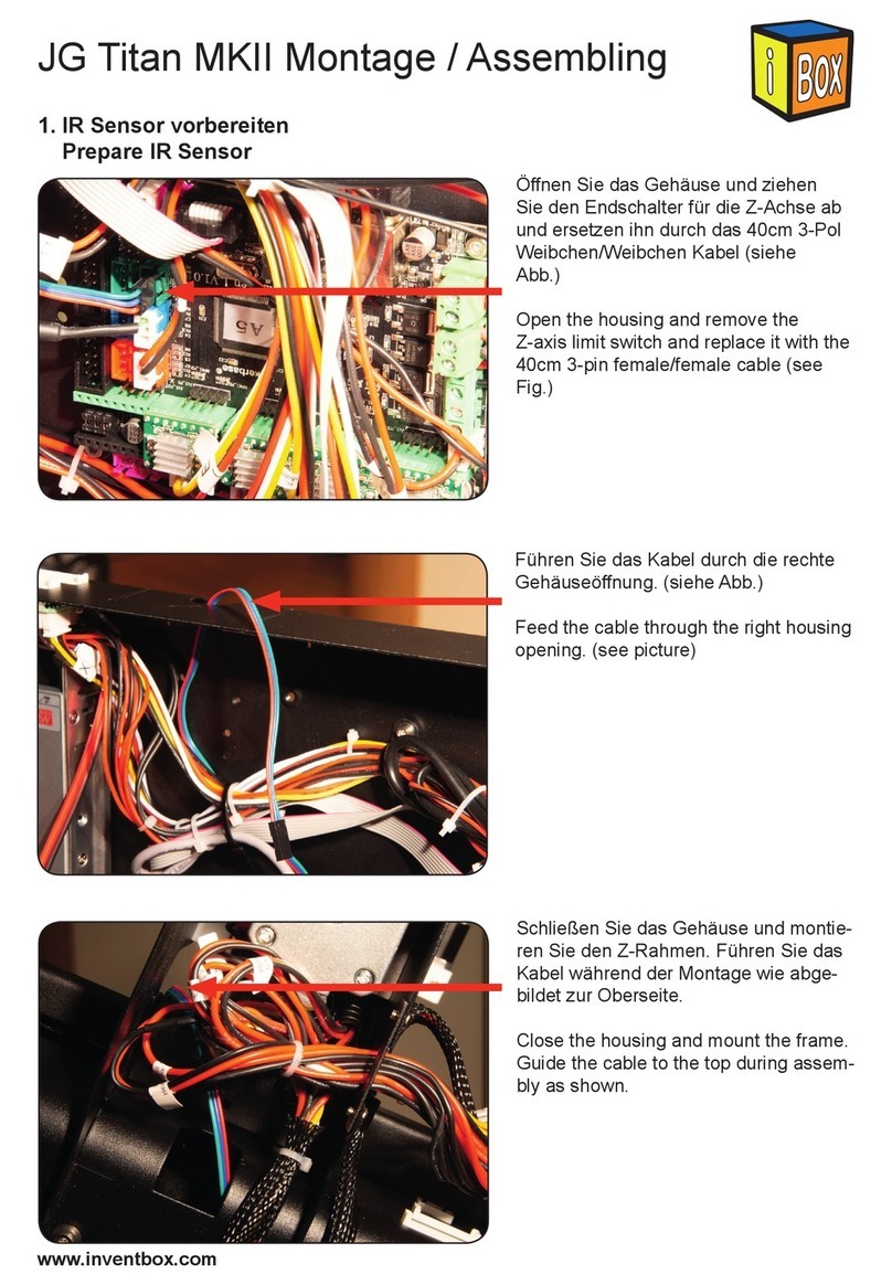
1. IR Sensor vorbereiten
Prepare IR Sensor
Ö󰀨nen Sie das Gehäuse und ziehen
Sie den Endschalter für die Z-Achse ab
und ersetzen ihn durch das 40cm 3-Pol
Weibchen/Weibchen Kabel (siehe
Abb.)
Open the housing and remove the
Z-axis limit switch and replace it with the
40cm 3-pin female/female cable (see
Fig.)
Führen Sie das Kabel durch die rechte
Gehäuseö󰀨nung. (siehe Abb.)
Feed the cable through the right housing
opening. (see picture)
Schließen Sie das Gehäuse und montie-
ren Sie den Z-Rahmen. Führen Sie das
Kabel während der Montage wie abge-
bildet zur Oberseite.
Close the housing and mount the frame.
Guide the cable to the top during assem-
bly as shown.
www.inventbox.com
A5A5 A5S / A1A5S / A1
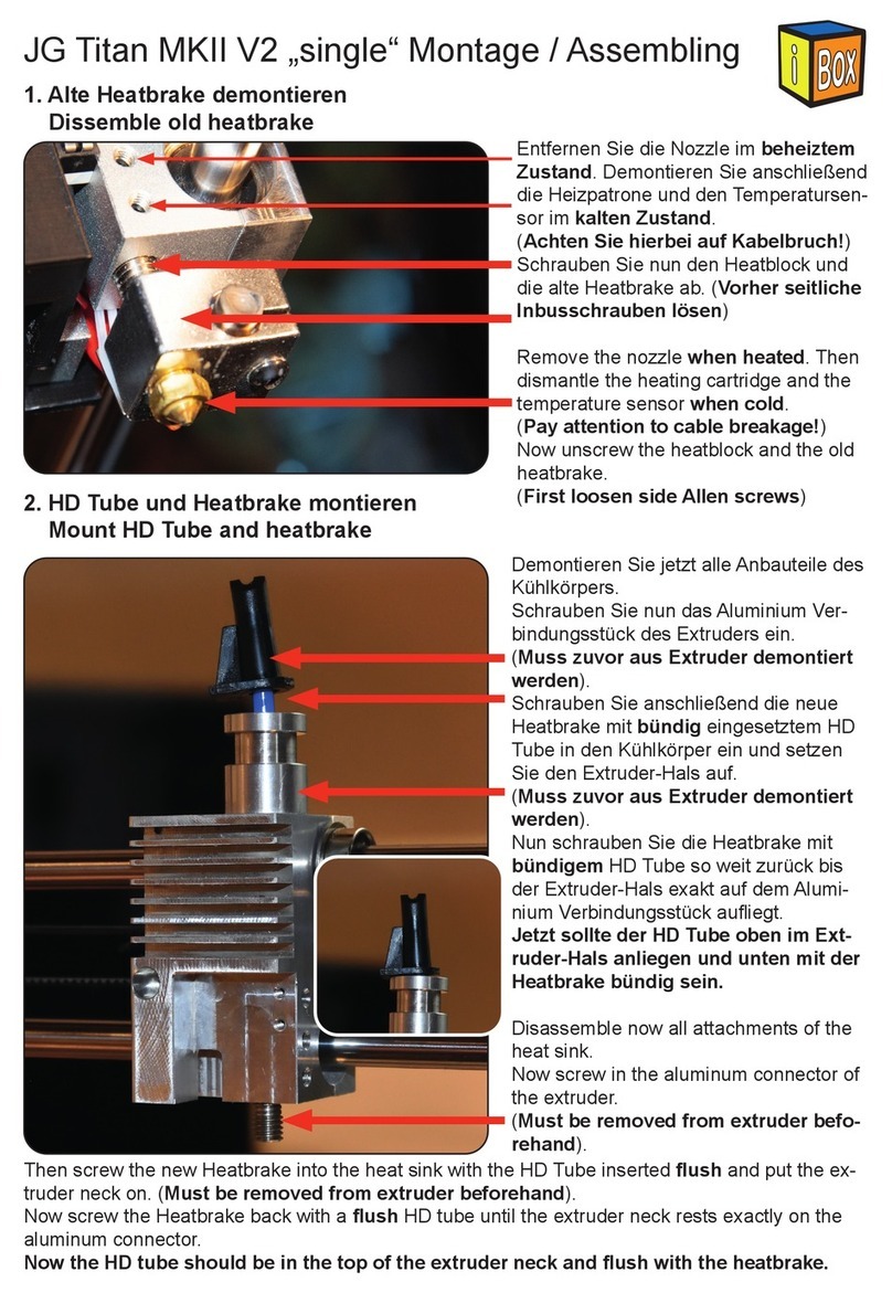
Demontieren Sie jetzt alle Anbauteile des
Kühlkörpers.
Schrauben Sie nun das Aluminium Ver-
bindungsstück des Extruders ein.
(Muss zuvor aus Extruder demontiert
werden).
Schrauben Sie anschließend die neue
Heatbrake mit bündig eingesetztem HD
Tube in den Kühlkörper ein und setzen
Sie den Extruder-Hals auf.
(Muss zuvor aus Extruder demontiert
werden).
Nun schrauben Sie die Heatbrake mit
bündigem HD Tube so weit zurück bis
der Extruder-Hals exakt auf dem Alumi-
nium Verbindungsstück auiegt.
Jetzt sollte der HD Tube oben im Ext-
ruder-Hals anliegen und unten mit der
Heatbrake bündig sein.
Disassemble now all attachments of the
heat sink.
Now screw in the aluminum connector of
the extruder.
(Must be removed from extruder befo-
rehand).
www.inventbox.com
3. HD Tube und Heatbrake montieren
Mount HD Tube and heatbrake
2. Alte Heatbrake demontieren
Dissemble old heatbrake
Entfernen Sie die Nozzle im beheiztem
Zustand. Demontieren Sie anschließend
die Heizpatrone und den Temperatursen-
sor im kalten Zustand.
(Achten Sie hierbei auf Kabelbruch!)
Schrauben Sie nun den Heatblock und
die alte Heatbrake ab. (Vorher seitliche
Inbusschrauben lösen)
Remove the nozzle when heated. Then
dismantle the heating cartridge and the
temperature sensor when cold.
(Pay attention to cable breakage!)
Now unscrew the heatblock and the old
heatbrake.
(First loosen side Allen screws)
Then screw the new Heatbrake into the heat sink with the HD Tube inserted ush and put the ex-
truder neck on. (Must be removed from extruder beforehand).
Now screw the Heatbrake back with a ush HD tube until the extruder neck rests exactly on the
aluminum connector.
Now the HD tube should be in the top of the extruder neck and ush with the heatbrake.
www.inventbox.com
5. Kühler montieren
Mount radiator
Setzen Sie den Kühler auf und ziehen
Sie die 2x M2x12mm Schrauben durch
den Endschalter und die 2x M2x5mm
auf der Gegenseite fest.
(Achten Sie auf die Kabelführung!)
Montage Details unter www.inventbox.
com
Put on the cooler and tighten the 2x
M2x12mm screws through the limit
switch and the 2x M2x5mm on the oppo-
site side.
(Pay attention to the cable guide!)
Assembly details at www.inventbox.com
!
4. Heatblock montieren
Mount heatblock
Montieren Sie nun den Heatblock und die Nozzle in um-
gekehrter Reheinfolge zu Schritt 1. Der Abstand zwischen
Heatblock und dem Nozzle Gewindeende sollte 1mm sein.
Now mount the heat block and the nozzle in reverse order to
step 1. The distance between the heatblock and the Nozzle
threaded end should be 1mm.
6. Seitendeckel vorbereiten
Prepare side cover
Legen Sie das 130cm 3-Pol Kabel mit
dem Weibchen in den Seitendeckel. Das
Kabel sollte ca. 10cm Herausstehen.
Insert the 130cm 3-pole cable with the
female into the side cover. The cable
should stand out about 10cm.
Sollten Sie unsere optionale Fullmetall Heatbrake (ArtNr.:
1020-2320) oder eine andere Nozzle verwenden, justieren Sie
das System bitte auf einen Abstand von 20mm von Noz-
zle-Spitze zu Unterseite-Kühlkörper.
If you are using our optional Full Metal Heatbrake (Art.:
1020-2320) or another Nozzle, please adjust the system to a
distance of 20mm from Nozzle Tip to Bottom Heat Sink.
www.inventbox.com
7. Extruder vorbereiten
Prepare extruder
Legen Sie alle Kabel durch den Seitendeckel. Achten Sie darauf, dass das Kabel des Tempera-
turfühlers zuletzt eingelegt wird!
Setzen Sie danach den Extruder auf das Aluminium Verbindungsstück auf.
Beachten Sie, dass Sie den Extruder später im Uhrzeigersinn ausrichten müssen, da sich
ansonsten das Aluminium Verbindungsstück wieder lockert!
Lay all cables through the side cover. Make sure that the cable of the temperature sensor is
inserted last!
Then place the extruder on the aluminum connector.
Note that you will have to align the extruder later in a clockwise direction, otherwise the
aluminum connection piece loosens!
8. Extruder montieren
Mount extruder
Setzen Sie den Extruder Deckel auf.
(Achten Sie auf den korrekten sitz der
Stellmutter für die Spannfeder!)
Drehen Sie nun den Extruder im Uhr-
zeigersinn in die korrekte Position und
montieren Sie den Seitendeckel mit den
3 Inbusschrauben.
Put the extruder lid on.
(Make sure that the adjusting nut for
the tension spring is in the correct
position!)
Now turn the extruder clockwise to the
correct position and mount the side co-
ver with the 3 Allen screws.
9. Seitendeckel xieren
Mount side cover
Schrauben Sie mit der M2x8mm Schrau-
be den Seitendeckel am Kühlkörper fest.
Screw the side cover to the heat sink
with the M2x8mm screw.
www.inventbox.com
Legen Sie alle Kabel und den PTFE
Schlauch in den Kabelkanal und ver-
binden Sie die beiden Lüfter sowie den
Temperaturfühler. Schneiden Sie nun
das überschüssige Ende Ab.
Insert all cables and the PTFE hose into
the cable duct and connect the two
fans and the temperature sensor. Now
cut o󰀨 the excess end.
10. Kabel in den Kabelkanal legen
Lay the cable in the cable duct
11. PTFE Schlauch kürzen
Cut PTFE Tube
Schneiden Sie den PTFE Schlauch auf
die korrekte Länge. Benutzen Sie keine
Zange oder Schere!
Cut the PTFE tube to the correct length.
Do not use pliers or scissors!
www.inventbox.com
Demontieren Sie die Frontplatte des
Druckkopfes und setzen Sie die beiden
schwarzen ABS Distanzhülsen in die
Bohrungen ein.
Disassemble the front panel of the
printhead and insert the two black ABS
spacers into the holes.
Schieben Sie dann den IR Sensor vor-
sichtig von oben nach unten auf.
Then carefully slide the IR sensor from
top to bottom.
Schrauben Sie den IR Sensor mit den
2x M3x12mm Schrauben mit viel Gefühl
fest und Verbinden Sie das Kabel wie in
der Abbildung.
Tighten the IR sensor very gently with
the 2x M3x12mm screws and connect
the cable as shown in the picture.
13. IR Sensor montieren
Mount IR Sensor
12. Kabel und Bowden xieren
Fix cable and bowden
Fixieren Sie den Kabelbaum mit Kabel-
bindern am Seitendeckel und stecken
Sie den Bowden in die Extruder Zufüh-
rung.
Fix the cable harness with cable ties on
the side cover and insert the bowden
into the extruder feeder.
www.inventbox.com
Verbinden Sie den Anschluss des alten
Extruders mit dem des neuen.
Connect the outlet of the old extruder to
that of the new one.
14. Extruder Stepper anschließen
Connect extruder stepper
15. IR Sensor anschließen
Connect R Sensor
Führen Sie das IR Sensor Kabel durch
den Kabelkanal und verbinden Sie es
mit dem Ausgang der Steuerung. An-
schließen können Sie die Kabel nach
unten schieben.
Pass the IR sensor cable through the
cable channel and connect it to the
output of the controller. Then you can
push the cables down.
Benutzen Sie ein Stück 1,78mm Fila-
ment um den alten Extruder in geö󰀨ne-
ter Stellung zu xieren. Schieben Sie
es nicht zu weit hinein, da es sonst die
Zufuhr blockiert!
Use a piece of 1.78mm lament to x
the old extruder in open position. Do not
push it too far, otherwise it will block the
supply!
16. Materialzufuhr frei machen
Free up material supply
www.inventbox.com
17. Kabelbinder verbauen
Assemble cable ties
Setzten Sie die Kabelbinder nach Ihren
Wünschen.
Put the cable ties according to your
wishes.
Für den nächsten Schritt ist es wichtig,
dass Sie das bett so gut es geht par-
allel zur Gehäuseoberseite ausrichten.
Stellen Sie alle 4 Ecken auf die gleiche
Höhe ein.
For the next step, it is important that you
align the bed as well as possible parallel
to the top of the housing. Set all 4 cor-
ners to the same height.
Benutzen Sie eine Schieblehre oder
etwas ähnliches um die X-Achse auf
beiden Seiten auf die gleiche Höhe zu
schrauben. Drehen Sie hierzu langsam
an den Spindelkupplungen.
Use a caliper or something similar to
screw the x-axis to the same height
on both sides. For this, slowly turn the
spindle couplings.
18. Druckbett ausrichten
Adjust Print Bed
19. X-Achse Ausrichten
Adjust X-Axis
www.inventbox.com
Auto-Leveling Basis / Auto-leveling base
Es ist es äußerst wichtig die X-Achse parallel zur Y-Achse auszurichten, da sonst kein klar
denierter Z-Referenzwert bei Bewegung der X-Achse möglich ist.
Iit is very important to align the X-axis parallel to the Y-axis, otherwise no clearly dened
Z-reference value will be possible when moving the X-axis.
20. Firmware ashen
Flash rmware
Laden Sie nun auf unserer Webseite
unter www.inventbox.com die neueste
Firmware herunter und installieren diese.
Hilfe zur Installation nden Sie unter
anderem auf https://jgaurorawiki.com/
Download and install the latest rmware
on our website www.inventbox.com.
For help with installation, visit https://
jgaurorawiki.com/
JOIN OUR Community !
Facebook Group: „JGAurora A5 / A5S / A3S / A1 MKII Upgrades“
21. IR Sensor einstellen
Adjust IR sensor
Für die erstmalige Einstellung des IR
Sensors ist es nötig die Nozzle 0,50mm
Nahe an das Druckbett zu fahren und
den Sensor so einzustellen, dass er
genau in dieser Höhe von 0,50mm
schaltet.
Benutzen Sie hierzu den beigelegten
Blech Kalibrierungsstreifen.
(Eine Umdrehung der Stellschraube ent-
spricht 0,5mm Höhe!)
IR Sensor ohne PC manuell justieren:
1. IR Sensor nach ganz unten stellen
2. G28 / Homing durchführen
3. Mit move auf Z=0 fahren
4. Abstand Nozzle zu Druckbett schätzen oder messen
5. IR Sensor um etwas weniger als den geschätzte bzw. gemessenen Abstand nach unten stellen.
6. G28 / Homing durchführen
7. Mit move auf Z=0 fahren
8. Abstand Nozzle zu Druckbett schätzen oder messen
9. IR Sensor um etwas weniger als den geschätzte bzw. gemessenen Abstand nach unten stellen.
(Schritte 2-9 so lange wiederhohlen, bis es möglich ist die Nozzle min. 0,5mm an das Druckbett zu
fahren).
10. Mit move in 0,1mm Schritten Nozzle an den Calibrierungsstreifen fahren bzw. 0,5mm zum
Druckbett ausrichten.
11. IR Sensor nach unter/oben stellen bis LED schaltet
IR Sensor mit Konsole manuell justieren:
1. IR Sensor nach ganz unten stellen
2. G28 / Homing durchführen
3. IR Sensor nach ganz oben stellen
4. M211 S0 (Z-O󰀨set deaktivieren)
5. Mit move in 1 und dann 0,1mm Schritten Nozzle an den Calibrierungsstreifen fahren bzw.
0,5mm zum Druckbett ausrichten
6. IR Sensor nach unter stellen bis LED schaltet
4. M211 S1 (Z-O󰀨set aktivieren)
7. M502 (reset)
www.inventbox.com
Für was benötige ich den beigelegten 110Ohm Widerstand?
Wir haben den Kühler zum drucken bei Temperaturen von bis zu
300c in Kombination mit einer Full Metall Heatbreak ausgelegt.
Sollten Sie dies nicht benötigen und bis max. 260c drucken, so
können Sie den beigelegten Widerstand vor den Lüfter einlöten
um diesen in seiner Lautstärke zu reduzieren.
JOIN OUR Community !
Facebook Group: „JGAurora A5 / A5S / A3S / A1 MKII Upgrades“
www.inventbox.com
21. IR Sensor einstellen
Adjust IR sensor
For the rst adjustment of the IR sen-
sor it is necessary to move the Nozzle
0,50mm close to the print bed and set
the sensor to switch exactly at this
height of 0.50mm.
Use the enclosed metall calibration
strip.
(One turn of the set screw corresponds
to 0.5mm height!)
Manually adjust IR sensor without PC:
1. Move the IR sensor to the bottom
2. Perform G28 / homing
3. Move to Z = 0 with move
4. Estimate or measure distance from nozzle to bed
5. Lower the IR sensor slightly less than the estimated or measured distance.
6. Perform G28 / homing
7. Move to Z = 0 with move
8. Estimate or measure distance Nozzle to bed of pressure
9. Lower the IR sensor slightly less than the estimated or measured distance.
Repeat steps 2-9 until it is possible to move the nozzle to the print bed by at least 0.5mm).
10. Move Nozzle to the calibration strip with 0.1 mm increments or align 0.50mm to the print bed.
11. Set IR sensor up / down until LED switches
Manually adjust IR sensor with console:
1. Move the IR sensor to the bottom
2. Perform G28 / homing
3. Move the IR sensor to the top
4. M211 S0 (disable Z o󰀨set)
5. Move Nozzle to the Calibration Strip with move in 1 and then 0.1mm increments or align 0.5mm
to the print bed
6. Replace IR sensor until LED switches
4. M211 S1 (activate Z o󰀨set)
7. M502 (reset)
For what do I need the enclosed 110 ohm resistor?
We designed the cooler for printing at temperatures up to 300c
in combination with a Full Metal Heatbreak. Should you not need
this and print max. 260c, so you can solder the enclosed resistor
in front of the fan to reduce it in its volume.
JOIN OUR Community !
Facebook Group: „JGAurora A5 / A5S / A3S / A1 MKII Upgrades“

Other manuals for JG Titan MKII V2

1

Other i-box 3D Printer manuals

i-box JG Titan MKII V2 User manual

i-box

i-box JG Titan MKII V2 User manual

i-box JG Titan MKII User manual

i-box

i-box JG Titan MKII User manual

Popular 3D Printer manuals by other brands

Cincinnati SAAM Equipment manual

Cincinnati

Cincinnati SAAM Equipment manual

gCreate gMax Printer 1.5+ quick start guide

gCreate

gCreate gMax Printer 1.5+ quick start guide

YIDIMU Panther user manual

YIDIMU

YIDIMU Panther user manual

Wasp DELTA 4070 Manual of use and maintenance

Wasp

Wasp DELTA 4070 Manual of use and maintenance

formlabs Fuse 1 manual

formlabs

formlabs Fuse 1 manual

Cobod BOD2-444 instruction manual

Cobod

Cobod BOD2-444 instruction manual

RS PRO WT280x manual

RS PRO

RS PRO WT280x manual

BIQU Thunder user manual

BIQU

BIQU Thunder user manual

LulzBot TAZ user manual

LulzBot

LulzBot TAZ user manual

Markforged Metal X user guide

Markforged

Markforged Metal X user guide

LulzBot TAZ quick start guide

LulzBot

LulzBot TAZ quick start guide

Artillery GENIUS installation manual

Artillery

Artillery GENIUS installation manual

Kora Pro 3D PC troubleshooting guide

Kora

Kora Pro 3D PC troubleshooting guide

Monoprice 21711 user manual

Monoprice

Monoprice 21711 user manual

3D Systems ProJet 4500 user guide

3D Systems

3D Systems ProJet 4500 user guide

Sindoh 3DWOX 2X user manual

Sindoh

Sindoh 3DWOX 2X user manual

Aibecy DY-H9 user manual

Aibecy

Aibecy DY-H9 user manual

zortrax FEP Film Replacement

zortrax

zortrax FEP Film Replacement

manuals.online logo
manuals.online logoBrands
  • About & Mission
  • Contact us
  • Privacy Policy
  • Terms and Conditions

Copyright 2025 Manuals.Online. All Rights Reserved.