21. Firmware ashen
Flash rmware
Laden Sie nun auf unserer Webseite unter www.inventbox.com die neueste Firmware herunter
und installieren diese. Hilfe zur Installation nden Sie unter anderem auf https://jgaurorawiki.com/
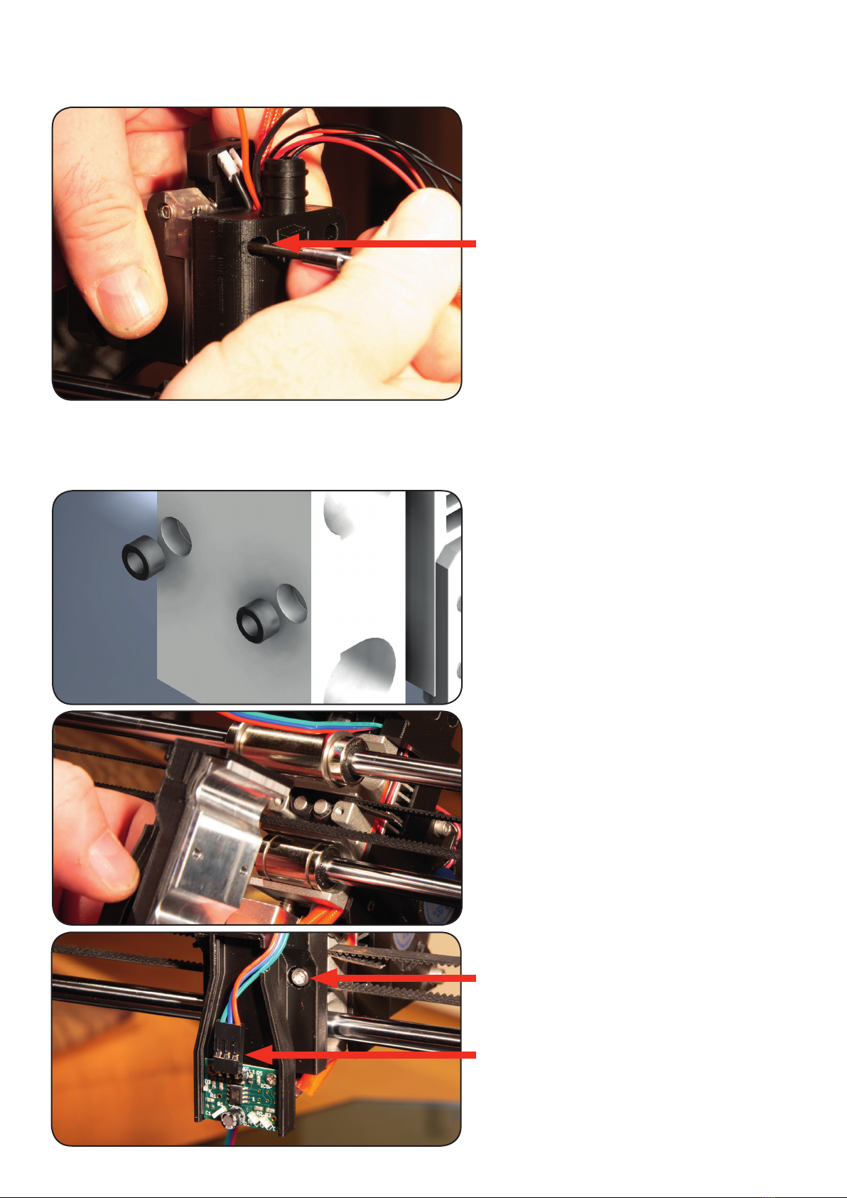
22. IR Sensor einstellen
Adjust IR sensor
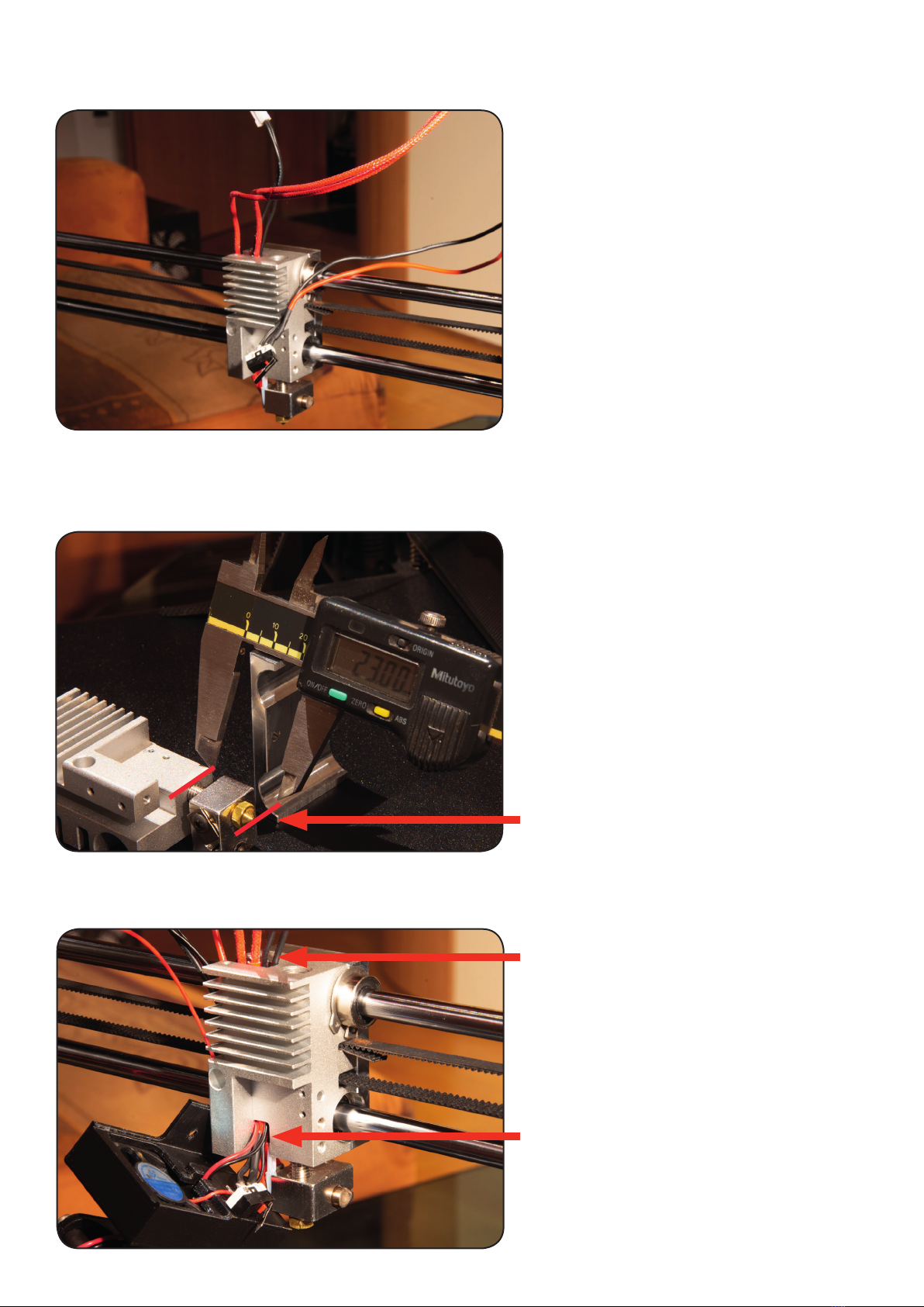
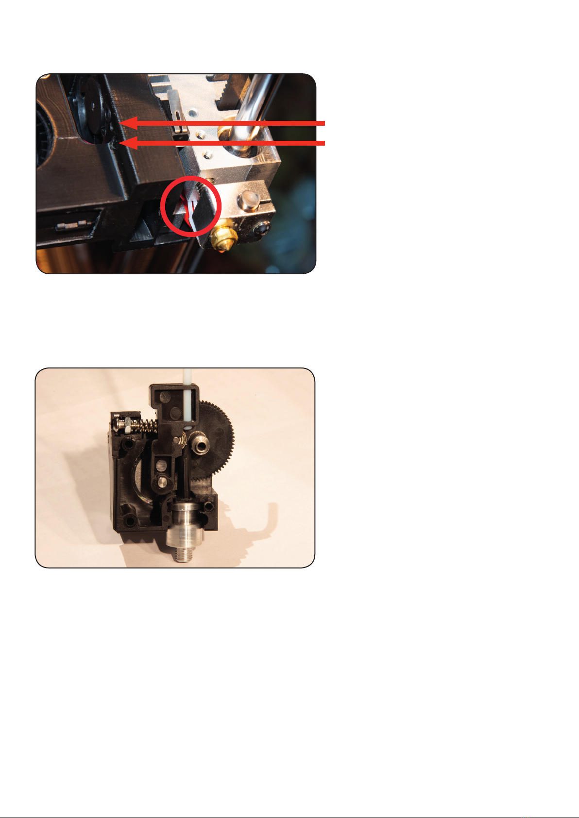
Für die erstmalige Einstellung des IR
Sensors ist es nötig die Nozzle 0,50mm
Nahe an das Druckbett zu fahren.
Die einfachste Methode ist, die Maschi-
ne mit dem „Home“ Button in das Druck-
bett fahren zu lassen und diese dann
schnell aus zu schalten.
(Nur bei kalter Nozzle!)
Wenn Sie dies Getan haben, schalten
Sie die Maschine wieder ein und fahren
durch „Move“ in 0,1mm Schritten so
lange nach oben bis der Kalibrierungs-
streifen unter die Nozzle gleitet. Jetzt
ist Ihre Nozzle ca. 0.50 - 0.60mm Vom
Bett entfernt und Sie können nun den IR
Sensor einstellen.
Hierzu drehen Sie die Stellschraube so lange nach rechts bis die Rote LED leuchtet. Jetzt ist Ihr
IR Sensor auf eine Höhe von ca. 0.50mm Eingestellt.
(Eine Umdrehung der Stellschraube entspricht 0,5mm Höhe!)
Jetzt wiederholen Sie dass Homing und die Nozzle sollte nun ca. 0,5mm Von der Oberseite ent-
fernt sein.
Sollte dies nicht der Fall sein, benutzen Sie den kalibrierungsstreifen indem Sie die Nozzle mit
„Move“ 0,1mm so lange nach unten oder oben fahren bis der Streifen exakt passt.
Jetzt stellen Sie den IR Sensor genau so ein, dass die LED exakt in dieser Position beginnt zu
leuchten.
Sollten Sie die Nozzle nicht weit genug nach unten fahren können, müssen Sie die Stellschraube
Schrittweise nach links drehen und erneut „Homing“ ausführen.
Feinjustierung des IR Sensors:
Nach Druckbeginn können Sie über den Button „More“ zu dem „Baby Stepping“ gelangen. Benut-
zen Sie „UP“ und „Down“ um während des ersten Layers die Höhe in 0,025 Schritten einzustellen.
Wenn Sie „Save“ drücken werden diese Einstellungen für den nächsten Druck gespeichert!
www.inventbox.com
Für was benötige ich den beigelegten 100Ohm Widerstand?
Wir haben den Kühler zum drucken bei Temperaturen von bis
zu 300c in Kombination mit einer Full Metall Heatbreak aus-
gelegt. Sollten Sie dies nicht benötigen und bis max. 260c
drucken, so können Sie den beigelegten Widerstand vor den
Lüfter einlöten um diesen in seiner Lautstärke zu reduzieren.