i-Optik CV-7800 User manual

COMPUTERIZED VISION TESTER
CV - 7800
OPERATOR’S MANUAL
1639

2
Contents
1.Introduction............................................................................................5
1.1 Product features and using range..........................................................................................5
1.2 Classify..................................................................................................................................5
1.3 Main performance index.......................................................................................................6
2.
Security considerations........................................................................10
2.1 Security identity.................................................................................................................. 10
2.2 Safety precautions before use............................................................................................. 10
2.3 During Use.......................................................................................................................... 12
2.4 After Use............................................................................................................................. 12
2.5 Maintenance and Check......................................................................................................13
2.6 Disposal...............................................................................................................................13
3.Configuration.......................................................................................14
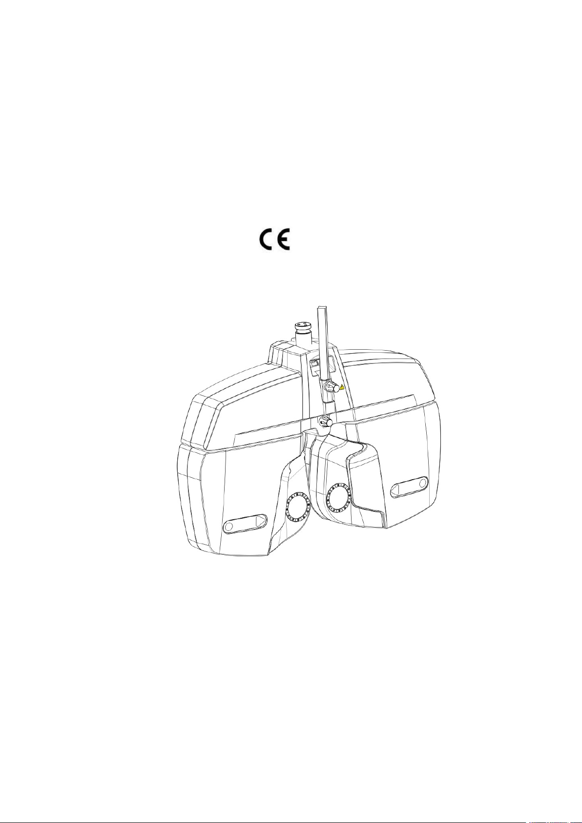
3.1 Refractor head configuration.............................................................................................. 14
3.2 Accessories..........................................................................................................................15
3.3 Identification....................................................................................................................... 16
4.Ready use.............................................................................................17
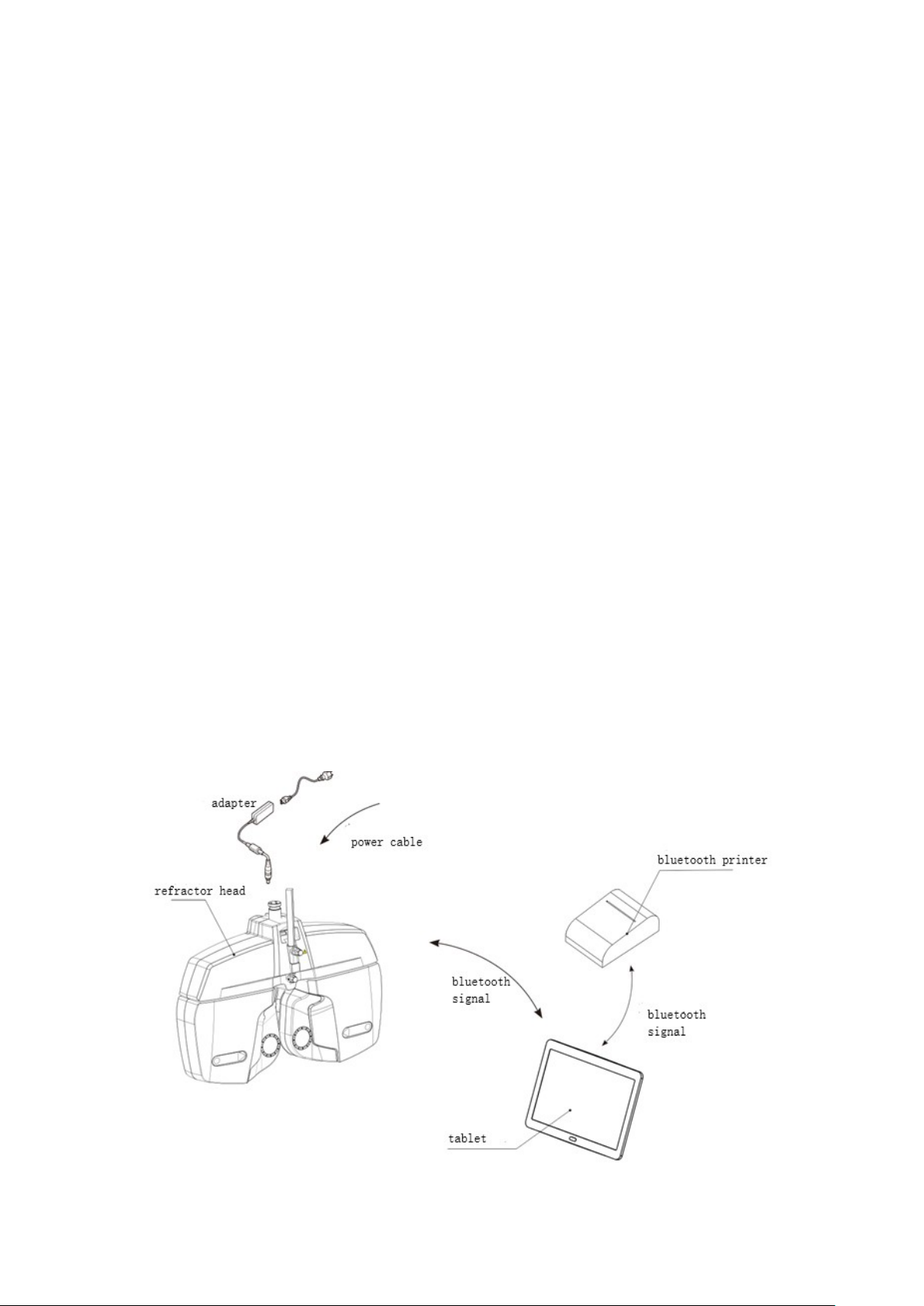
4.1 Setup connection of the device........................................................................................... 17
4.2 Install near vision chart.......................................................................................................18
4.3 Install face shield................................................................................................................ 19
4.4 Install and remove the forehead assemble..........................................................................20
4.5 Adjust the level................................................................................................................... 20
4.6 Alignment cornea................................................................................................................21
4.7 Using near vision chart....................................................................................................... 21
5.Tablet application interface and function introduction.......................24
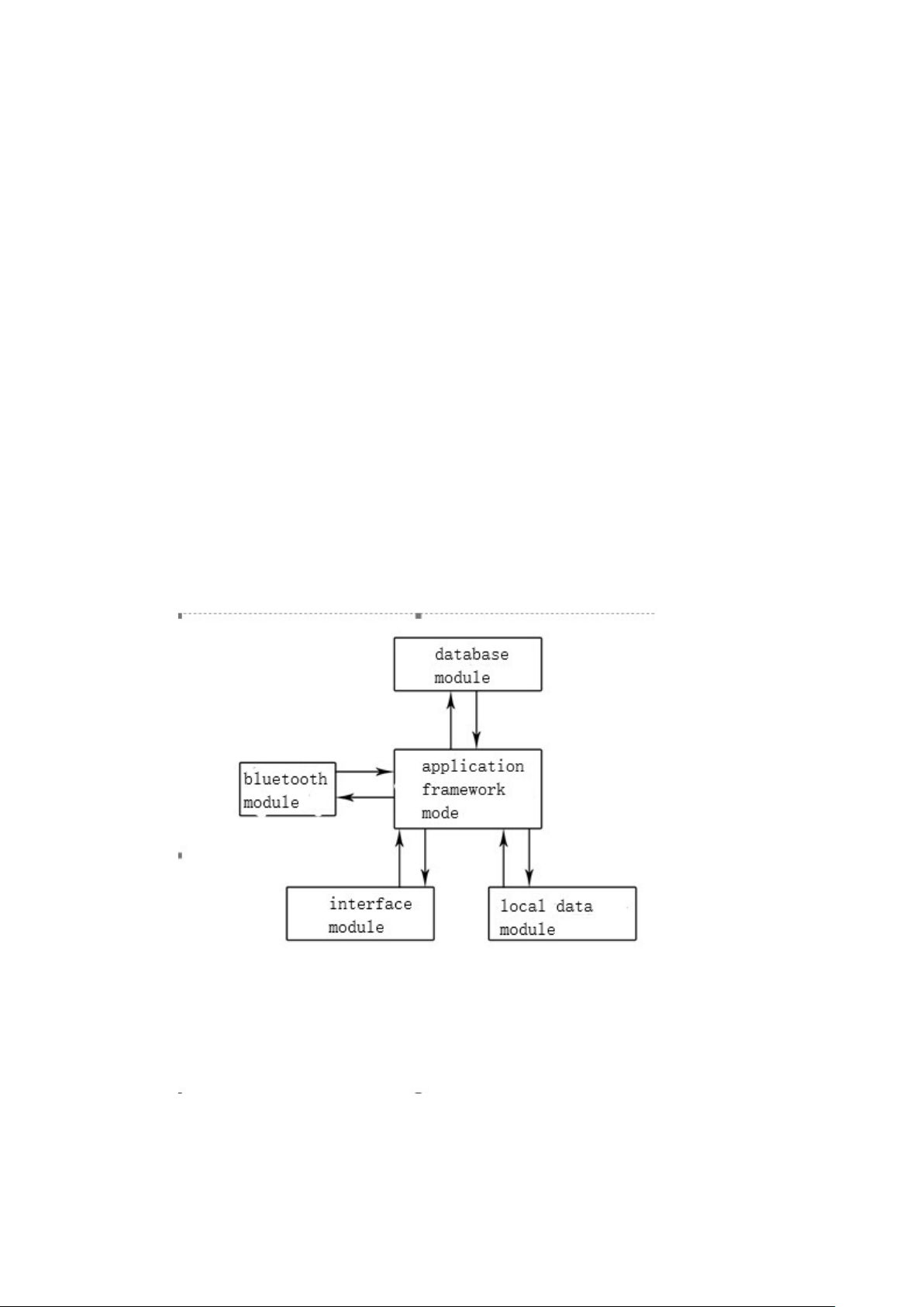
5.1 Main interface introduction and function description........................................................ 24
5.2 Refractor head operate and data display area.....................................................................25
5.2.1 Refractor head data display area..............................................................................25
5.2.2 Optometry condition switch operating area.............................................................30
5.2.3 PD test and NC test area.......................................................................................... 31
5.2.4 Right/ Left eye auxiliary lens operate buttons.........................................................33
5.2.5 Optometry item data plus or minus button and simulate plate................................33
5.2.6 Crossed cylinders operate button.............................................................................34
5.3 Monitor chart operate area.................................................................................................. 35
5.3.1 Vision chart type switching area.............................................................................. 36
5.3.2 Vision chart selection area....................................................................................... 36
5.3.3 Vision chart display and occlusion operation area...................................................37

3
5.3.4 Vision chart state and vision chart working mode switching area...........................38
5.3.5 User-defined vision atlas editing interface.............................................................. 38
5.4 The system state and menu area..........................................................................................41
5.4.1 The use of customer information management module.......................................... 42
5.4.2 The use of custom program module.........................................................................46
5.4.3 External connection equipment management..........................................................52
5.5 Fast reset and basic Settings............................................................................................... 57
5.5.1 Change the system Settings..................................................................................... 57
6.Instrument operation............................................................................58
6.1 Checking with fog...............................................................................................................58
6.2 Precise inspection astigmatism axis and degree................................................................. 60
6.3 Accurately measure sphere degree if there is a deviation.................................................. 61
6.4 Binocular balance test.........................................................................................................62
6.5 Heterophoria measurement.................................................................................................63
7.
Printer using...........................................................................................65
7.1 Basic function of the printer............................................................................................... 65
7.1.1 Turn on..................................................................................................................... 65
7.1.2 Shutdown................................................................................................................. 65
7.1.3 Self-inspection......................................................................................................... 65
7.1.4 Battery Charging......................................................................................................65
7.2 Printing mode......................................................................................................................66
7.3 Printer indicator and buzzer signal introduction.................................................................66
8.Self diagnosis and maintenance.......................................................... 66
8.1 Troubleshooting.................................................................................................................. 66
8.2 Clean and disinfect..............................................................................................................67
8.3 Scrapping............................................................................................................................ 68
9.Dimensions and other specifications...................................................68
9.1 Appearance specifications, contraindicati.......................................................................... 68
9.2 use age.................................................................................................................................68
9.3 disclaimer statement........................................................................................................... 68

4
Please read this manual before use.
This device is manufactured accord to GB9706.1 Medical electrical equipment
general requirements for safety, have to connect the power plug to a grounded outlet.
In order to ensure use the product safely, and prevent damage to operator and other people, or
cause a loss of other devices, warning labels are indicate on the machine as well as in the manual,
please pay attention and read the accompanying documents carefully.
ISO 9001/13485 certification—R&D, Manufacture and service of the products by Our company
have passed ISO 9001/13485 certification. IEC standards applied in this manual. The dioptre are
indicated with a reference wavelength of 546.07nm. Materials in direct contact with the patient
passed the ISO10993 assess, not made up unacceptable risk.
The safety precautions and operating procedures must be thoroughly understood before using the
device. And please safekeeping this manual. If you encounter any problems or have questions
about the device, please contact Ningbo Ming Sing’s local authorized distributor or contact with
our customer service department directly.
This manual is meanwhile as a training reference manual, in order to ensure best operating
performance of the new machine, please read carefully and operating accord to process in this
manual. Please reserve this manual for reference for communicate with other users in the future. If
addition copy needed or have questions about this device, please contact our company or
authorized distributors.
Information contained in this manual has been confirmed when publish. Product specifications are
subject to change without prior notice. The rights of change the product which contains in this
manual is reserved by our company, and without prior notice. Sold products does not involve in
this change.
Do not copy, retrieve, distribute any chapters of this book by electronic, mechanical, recording or
any other means if not written approval by our company.

5
1.Introduction
Computerized vision tester (hereinafter referred to as vision tester) is used to subjective
examination of visual acuity and refractive error of subject’s eyes.
1.1 Product features and using range
a) Electric shock protection type: Class I external power supply device
b) Electric shock protection level: BF type
c) liquid inlet protective degree classification: Common device
d) Applied part: forehead rest
e) Power supply type: single phase, net power supply: 100-240V, 60/50Hz, 85VX
f) Not a AP or APG type device
g) Mode of operation: Continuous operation
h) This machine is a impermanence installation device
i) This machine is not a portable device. Out supports or brackets used with this device
must apply with the safty precautions in this manual or other applicable standards.
1.2 Classify
The mode of this device is CV-7800
This device is constitute by refractor head, software(rev.V4.0. V4.0.150915
for tablet and computer), and adapter, as showing in Figure 1.1
Figure 1.1

6
Storage and transport environment conditions:
Temperature: -10~55℃
Humidity: 10~85%
Air pressure: 700hPa~1060hPa(transport), 500hPa~1060hPa(storage)
Working environment condition:
a) Temperature : 10℃-~+40℃
b) Humidity ≤80%
c) Air pressure: 760hPa - 1060hPa
Power adapter requirement
a) Input:AC 100-240V~50/60Hz
b) Output:DC 24V 2.5A 60VA
Software operating environment
Software version: V4.0.150915
Operation system: Android 4.3.2 and above
Processor main frequency: 1.0GHz and above
System memory: 1GB and above
Memory: 4GB and above
Resolution: 1920*1200 and above
Bluetooth: 2.0 and above
Software naming rule:
Software version number is consist of 4 parts:
Part A is the main version, indicating major update and upgrade of the software. Initial vaule
is 1. When there is major upgrade, it will change to V2,V3,V4 for each major change.
Part B is sub level version, indicating minor upgrade of the software. Initial version 0, will
add 1 each time there is a minor upgrade of the software.
Part C is revise version, indicating the corrective upgrade for the software. Initial value
000000. Each time there is a correction, these 6 digit will change to the date of correction.
Eg, if the software is constructed on Oct 8, 2018, then it will change to 121008.
Bluetooth parameter
Model: HM-10 V4.0BLE
Bluetooth protocol: Bluetooth Specification V4.0BLE
No byte limit for port communication
In open filed can connect to iPhone 4s in 100 meter
USB protocol: USB V2.0
Frequency: 2.4GHz ISM band
Modulation Mode: GFSK(Gaussian Frequency Shift Keying)
Transmitting frequency: -23dbm,-6dbm,0dbm,6dbm, can be changed through AT order
Sensitivity: ≤-84dbm at 0.1%BER
Transmission speed: Asynchronous:6K bytes
Synchronous:6K Bytes
Security feature: Authentication and encryption
Support services: Central&Peripheral UUID FFE0,FFE1
Power consumption: in stand by mode, current 400uA-800Ua, communication current
8.5mA
Supply power: +3.3VDC 50Ma

7
Working temp: -5-+65 Centigrade
Size: M-10 26.9mm×13mm×2.2mm
Vision tester control software
The control software is a tablet control software based on android system. By controlling the
system to perform specified operations, and interacting with customers, optometry analysis and
diagnosis can be conducted, finally generate report and corresponding prescription can be provided.
Through the bluetooth module, the refractor head control software takes the tablet as the
center, and integrates the operating terminal, refractor head, ARK, LCD chart display and
prescription printer, which are isolated units in the traditional optometric system, into bluetooth
LAN, so as to realize real-time data transmission and form an organic whole. By bluetooth
communication, user can have a more rapid and stable lens combination control; and the accurate
and fast combination of sphere lens, cylinder lens, axis and prism, fast switch of special lens, fast
load and reading of the test result, as well as sensitive and reliable control of chart display, and
reliable printer export all can be realized.
The vision tester control software provides optometrist a more comprehensive, convenient
and stronger refraction and assistance system. By tablet, the fast lens switch and combination is
realized. Through the customized program edit system, the optometrist can save his experience
through program procedures to improve efficient. Show specified optotypes on the chart display
can have more flexible control of the chart display. And the user can use user-defined optotype
function to improve efficiency. Also user can establish database for patient info, to save and share
the real-time result, pushing the traditional refraction process into internet era.
The vision tester control software makes a new interpretation of the traditional optometry
process, integrates the advanced mobile terminal into the modern optometry system, and integrates
the ideas of the optometrist's personality customization and the era of Internet data, bringing a fast,
fashionable and scientific optometry experience.
1.3 Main performance index

8
1.3.1Measurement range
Sphere:+16.75D ~-19.00D
Cylinder:0D ~-6.00D
Axis:0º~180º
Prism:0△ ~ 20△
Prism base: 0º-360º
PD range: 50mm - 80mm
1.3.2 Step
Sphere: 0.25D/0.5D/3.0D
Cylinder: 0.25D
Axis: 1º/5º
Prism: 0.1△/0.5△
Prism base minimum measure step: 1º
PD: 0.5mm
1.3.3 Tolerance
a) The tolerance of sphere should accord with the requirement table 1.1
Table 1.1 sphere tolerance
Item Standard request Tolerance
Sphereф(D)0.00≤︱ф︱≤3.00 ±0.06
Remain
Astigmatic≤
0.03
3.00<︱ф︱≤6.00 ±0.09
6.00<︱ф︱≤9.00 ±0.12
9.00<︱ф︱≤12.00 ±0.15
12.00<︱ф︱≤15.00 ±0.18
15.00<︱ф︱±0.25

9
b) The tolerance of astigmatic power should accord with the requirement table 1.2
Table 1.2 Astigmatic power tolerance
Meridian direction
maximum absolute
diopter
Astigmatic power nominal diopter
≤0.50 >0.50-1.00 >1.00-3.00 >3.00-6.00 >6.00
Tolerance D
0.00-5.00 0.06 0.06 0.06 0.09 0.12
>5.00-10.00
>10.00-15.00 0.09 0.12 0.18
>15.00 0.09 0.12 0.18 0.25
c) The optical center tolerance of mechanical system of sphere and cylinder combinative
optical system should accord with the requirement table1.3
Table1.3 optical center tolerance of mechanical system of sphere and cylinder combinative optical
system
d) Prism tolerance should accord with the requirement of table 1.4
Table1.4 Prism tolerance
Nominal diopter(cm/m)Tolerance
≤5.00 ±0.25 cm/m
Nominal diopter(Absolute)DTolerance cm/m
0.00 0.12
>0.00-6.00 0.25
>6.00-12.00 0.37
>12.00 0.50

10
>5.00
±
5%
e) Cylinder axis and prism base tolerance should accord with the requirement of table 1.5
Table 1.5 Cylinder axis and prism base tolerance
f) PD and the reference range scale should accord with the requirement of table 1.6
Table 1.6 Tolerance of the PD and the reference range
Item Tolerance mm
VD ±0.5
PD ±0.5
1.3.4 Structure and function
1.3.4.1 The minimum aperture of all the lens of vision tester should be not less than 16mm, for the
prism equal to or more than 6cm/m, the aperture can be reduced to 11mm.
1.3.4.2 Manufacturer should indicate the reference plant of vision tester, both sides should have
the identify of reference range.
1.3.4.3 The vision tester should have at least one set of mask and dichoptic device, each system
should mount a Jackson cross cylinder.
1.3.4.4 Forehead rest adjust range should be at least 10mm.
1.3.4.5 Observational systems should be without reflected light and scattered light.
1.3.4.6 Structure of lens cavity should be not influence the patient examine.
1.3.4.7 The device should be alignment and centered when the lanes and accessory fixed in front
of the sightglass.
Item Nominal diopter(Absolute)Tolerance
Cylinder axis
>0D-0.25D ±5º
>0.25D-1D ±3º
>1D ±2º
Prism base
≤1 cm/m ±5º
>1 cm/m -10 cm/m ±3º
>10 cm/m ±2º
Remark: the zero position of cylinder axis and prism base is defined as: the direction of the line of
centers when the height different of both sides of the device is adjust to zero

11
1.3.4.8 The device should be equipped with auxiliary lens, every auxiliary should be identify
corresponding.
1.3.4.9 The device using LCD display, the displayed character, data and curve should be clear.
1.3.4.10 The PD should be able to continuous adjustment, the range is no less than
50mm—80mm.
1.3.4.11 All the lens disks should be installation corresponding lenses as fixed data, the center of
lenses and holes should be alignment.
1.3.4.12 All the buttons of the device are identification clearly, function and status should be
convert normally when press the keys.
1.3.4.13 This device is with testing result print function.
1.3.4.14 The device is with bluetooth communication, functional distance 10m.
1.3.5 Appearance
1.3.5.1 The surface of vision tester should be smooth, bright and clear, cannot have etch pit, dirt,
scratch and front, rags and etc.
1.3.5.2 Effective clear aperture of the vision tester’s optical element cannot have bubble, defect,
scratch and any macroscopically observable irregular surface defects.
1.3.6 Material biocompatibility
The material which contact with the patient (forehead rest and face shield) should be
according to the follow requirement:
a) No cytotoxicity.
b)No delayed type hypersensitivity.
1.3.7 Cleaning and disinfect measure
1.3.7.1 The part and nearby part where contact with the patient or operatives should be liable to
clean. No disinfections dead angles should be on the parts which need to disinfect.
1.3.7.2 Please cleaning and disinfect the device according to this user manual, should not cause
device damage or material deteriorate, or affect to the security protection performance.
1.3.8 The environment test of computerized vision tester should be accord with the requirement of
climate environment Ⅱmechanical environment test group Ⅱin GB/T14710-2009

12
1.3.9 Safety requirements should accord with stipulates in GB9706.1
1.3.10 EMC: should meet requirement of YY0505-2012.

13
2. Security Precautions
2.1 Security identity
In this manual, words used to indicate the security alert degree or level are defined as follows:
warning
Warning: indicates a potentially dangerous situation, such as can't be
avoided, could result in death or serious injury.
attention
Attention: indicates a potentially dangerous situation, such as can't be
avoided, may result in slight or moderate injury or property damage.
Under certain conditions, even if the conditions for attention are also likely to lead to serious
damage. So safety precautions must be strictly abided by the moment.
2.2 Safety precautions before use
warning
• Be sure to secure the refractor head to the refractor arm.
If the refractor head is dropped or falls, injury or device failure may be caused.
Make sure the power case is installed according to figure 1 in part 1.2 of this manual:vertical
mounting
CAUTION
• The safety precautions and operating procedures must be thoroughly understood before using the
device.
Unintended use may cause unexpected malfunction or adverse experience.
• Do not store the device in an area that is exposed to rain or water, do not put any container which
with gas or liquid.
• Do not store the device in dusty, hot, humid places or in direct sunlight.
• When moving the device to another place, do not carry it alone.
Back injury may occur or the device may fall.
• Install the device on a stable and level surface.
If the device falls, injury or device failure may result.
• Never install the device in a place where it is exposed to water.
Contact with liquids may cause electric shock or device failure.
• Install the device in an environment that meets the following conditions.
The following conditions must be maintained during use.
Temperature: 10 to 40 ºC (50 to 104ºF)

14
Humidity: ≤85%
Pressure: 760 to 1060 hPa
Installation place: Interior
No hazardous dust or smoke
A dust-free place
A place free from vibration and shock
• Be sure to level the refractor head before use.
Failure to do so could affect the data accuracy. Level the refractor head by turning the
leveling adjustment knob until the bubble is centered in the level.
• Be sure to use a wall outlet which meets the power specification requirements.
If the line voltage is too high or too low, the device may not operate properly. Malfunction
or fire may result.
• Connect the power plug to a grounded outlet to avoid electric shock
• Do not overload the electrical outlet.
Or else fire may result.
• Fully insert the power plug into the outlet.
Imperfect connection may cause fire.
• Do not use any power cord other than that equipped. Do not use the equipped power cord for
purpose other than as intended.
Or else malfunction or fire may result.
• Do not place heavy objects on the power cord.
A damaged power cord may cause fire or electric shock.
• When installing and operating the device, observe the following instructions about EMC
(electromagnetic compatibility):
- Do not use the device simultaneously with other electronic equipment to avoid electromagnetic
interference with the operation of the device.
- Do not use the device in the same room with other equipment such as life-support equipment,
other equipment that has major affects on the life of the patient and results of treatment, or other
measurement or treatment equipment that involves small electric current.
- Do not use the device simultaneously with portable and mobile radio frequency communication
systems because it may have an adverse effect on operation of the device.
- Do not use cables and accessories that are not specified for the device because that may increase
the emission of electromagnetic waves from the device or the system and decrease the resistance
of the device to electromagnetic disturbance.
If potential electromagnetic interference between equipment with other equipment, shielding
measures should be taken or change the placement of this equipment, in order to reduce the
possibility of interference.

15
2.3 During Use
WARNING
• When moving the refractor head, make sure that there are no obstacles in the path.
If the arm is swung carelessly, it may bump against someone or something and injury or
malfunction may occur.
CAUTION
• Keep the measuring windows free of fingerprints and smudges.
Failure to do so could affect the data accuracy.
• In the event of smoke or strange odors, immediately turn off the device and disconnect the power
plug from the outlet. After you are positive that the smoke has stopped, contact Ningbo Ming
Sing or your authorized distributor.
Continued use of the device under such abnormal conditions may cause fire or electric shock.
• When the device is not in use, please turn it off and put the dust cover over it.
If the device is not covered for an extended period, the accumulation of dust may affect the data
accuracy.
• Perform the visual and operation checks before using the device. If any abnormality is found, do
not use the device.
Continued use of the device under such abnormal conditions may affect the data accuracy.
Unexpected malfunction or faulty diagnosis may induce unexpected health
hazards.
• Before each patient, always clean the patient's contact area (forehead rest and face shields) using
disinfectant alcohol.
• This instrument must be operated by the trained or qualified people, or after their instruction.
2.4 After Use
CAUTION
• If the device will not be used for the extended period, disconnect the power cable from the wall
outlet.
• Occasionally clean the prongs of the power plug with a dry cloth.
If dust settles between the prongs, it may collect moisture, and short circuit or fire may result.
• Do not yank the power cord to disconnect it from an outlet.
This can damage the metal core of the cord and may result in electric shock, short circuit or fire.

16
2.5 Maintenance and Check
CAUTION
• Any repair or service to the instrument must be done by Ningbo Ming Sing Optical R & D Co.,
Ltd or people trained and can be operate correctly with experience or contact with the authorized
distributor to do the maintenance.
• Screw out the safe screw may cause the machine separate from the support arm and cause the
serious damage.
• Do not open the body cover or try to repair the interior components. Any repair or service to the
instrument must be done by experienced staff from Ningbo Ming Sing Optical R & D Co., Ltd or
the authorized distributor.
• The adjustment must be done by Ningbo Ming Sing Optical R & D Co., Ltd technician or other
authorized staff.
• The refractor head operation must be strictly according to the user manual. If not follow the user
manual, the patient safety and the normal work of instrument can not be guaranteed.
CAUTION
• Never use organic solvents or high washing power detergent to clean the exterior of the device.
It may ruin the surface of the device.
• Never put the refractor head into the liquid, otherwise it will broke the machine.
• Avoid touch the optical components to prevent leaving fingerprint or oil stain to decrease the
performance.
2.6 Disposal
CAUTION
Follow the local ordinances and recycling regulations regarding disposal or recycling of the
components.
It is recommended to commission the disposal to a designated industrial waste disposal contractor.
When disposing of packing material, follow the local ordinances and recycling regulations.

17
3.Configuration
3.1 Refractor head configuration
Figure 3.1
1) Examination window……….The patient’s eyes are observed through the window, and patient
observe charts through the window.
2) Near vision illumination…..…Light up when near vision testing, light off when far vision

18
testing.
3)Corneal aligning windows……The position of patient’s cornea can be observed through the
window.
4)Forehead rest adjust knob……Moves the forehead rest forward and backward in order to adjust
the VD.
5)Near-point rod holder………….The near-point rod is inserted and attachedhere.
6)Near-point rod clamp screw…..Fix the near-point rod.
7)Spirit level……………………………Used to confirm that the refractor head is level.
8)Leveling knob………………….Adjust the level of the refractor head.
9)Forehead rest magnet………….Fix the face shield.
10)Forehead rest…………………The patient’s forehead rests here when test.
11)Cornea alignment scale………Measures the VD.
3.2 Accessories
Figure 3.2
12)Face shield (2 sets.)………..Attached to the instrument to put the patient’s face in place, use
one while the other is being sterilized.
13)Dust cover…………………Covers and protects the instrument body from dust and dirt during
storage.
14)Forehead rest (2 sets.) ……. The patient’s forehead rests here. Detachable by a touch, use one
while the other is being sterilized.

19
15)Near-point rod……………The card holder is attached at the near point examination position.
16)Card holder…………………The near-point card is attached.
17)Operator’s manual………… Describes instructions about handling the instrument
18)Near-point card…………….. Contains the near-point charts, for test the near
vision.
Warning
The accessory in this device supplied by our company, other supplier’s accessory could be use
only after verify the safety by our company
3.3 Identification
The following identifications applied on this device
1282
Accord with basis requirement of EU MDD
93/42/EEC
Moisture proof
Read operator’s manual
Insulation type BF device
Electronic electrical equipment scrap disposal
requirements
Manufacturer
EU authorized representative
Production date
Warning mark, read operator’s manual before use
Series number
“I” and “O” representative power switch(ON)and
(OFF)separately
AC
Fuse indicate

20
The place of warning mark
Figure 3.3
There is warning mark in front of device: Do not close to the near point rod, prevent of
crushing
4.Ready use
4.1 Setup connection of the device
Profession staff of our company or authorized personnel who have been trained by our
company are required on the installing process.
It use with a secure connector if the refractor head install on the stand or ophthalmic unit
which from other companies, as showing in figure 4.1. Adjust the leveling knob which is showing
in figure 3.1 after connect the refractor head, to make the refractor head at level condition.
Table of contents