i-team i-vac 5 User manual

3
Preface
Thank you for purchasing the i-vac 5®. The i-vac 5 has an egg shaped canister so you can work
optimal in smaller areas and carry it close to your body. All of the accessories and necessary
equipment supplied with the machine can be stored on the machine.
The i-vac 5 is easy to use when you follow the instructions. Please read the user manual carefully.
Become familiar with the correct operation and maintenance procedures. Store the manual in a safe
place. The manual is an essential part of the i-vac 5 and must be handed over to the new owner upon
resale or exchange. Each i-vac 5 has a unique identification number that can be found on top of the
main body. Your i-team partner needs this number when you order parts.
When this manual refers to “the manufacturer” this means: Future Cleaning Technologies B.V.,an
affiliate company of i-team in Eindhoven, the Netherlands. When this manual mentions “the partner”
your local i-team resell and support service partner is referred to.
Purpose of the user manual
The purpose of the user manual is to provide the user with information during the life of the i-vac 5
in such a way that the i-vac 5 is used correctly, efficiently and safely, even in the event of reasonably
foreseeable misuse.
The user manual contains instructions regarding:
•personal operator safety;
•intended and non-intended use of the i-vac 5;
•instructions for daily use;
•maintenance instructions;
•storage conditions;
•disposal of the i-vac 5.
These instructions must be considered to avoid risks that could lead to physical and/or material
damage.
Target audience
This user manual is intended for operators of the i-vac 5 and their supervisors, as well as partners
and importers.
Operators of the i-vac 5
The i-vac 5 may only be operated by a person who:
•has correctly read and understood the instructions in this manual;
•is trained by an experienced operator who has read and understood the instructions in this
manual.

4
Reading guide
The following symbols and terms are used throughout this manual to alert the reader to
safety issues and important information:
Symbol
Term
Explanation
WARNING
Indicates a hazardous situation which, if the safety
instructions are not followed, can lead to injuries of the
operator or bystanders, light and/or moderate damage
to the product or the environment.
CAUTION
Indicates a hazardous situation which, if the safety
instructions are not followed, can lead to light and / or
moderate damage to the product or the environment.
ATTENTION
Indicates a liability situation, where the manufacturer
or its partners and affiliates cannot be held accountable
for damages caused by non-compliance.

5
Content
Preface .................................................................................................................................................................... 3
Purpose of the user manual.................................................................................................................................... 3
Target audience ...................................................................................................................................................... 3
Operators of the i-vac 5 .......................................................................................................................................... 3
Reading guide.......................................................................................................................................................... 4
1Introduction.................................................................................................................................................... 7
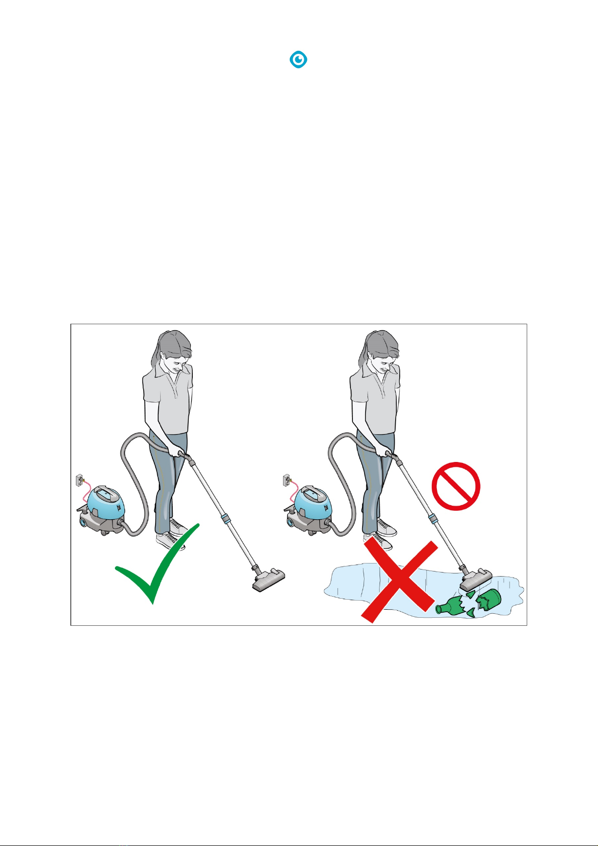
1.1 Intended use of the product.................................................................................................................. 7
1.2 Non-intended use of the product.......................................................................................................... 8
1.3 Lifespan.................................................................................................................................................. 9
1.4 Modifications......................................................................................................................................... 9
1.5 Specifications......................................................................................................................................... 9
1.6 Warranty.............................................................................................................................................. 10
1.7 Identification ....................................................................................................................................... 10
2Description ................................................................................................................................................... 11
3Safety............................................................................................................................................................ 12
3.1 General Safety Instructions ................................................................................................................. 12
3.2 Risks during operation......................................................................................................................... 12
4Transport and storage .................................................................................................................................. 13
5Assembly and installation............................................................................................................................. 14
5.1 Unboxing.............................................................................................................................................. 14
5.2 Assembly.............................................................................................................................................. 15
5.3 Replacing the dust bag ........................................................................................................................ 16
6Operation ..................................................................................................................................................... 20
6.1 Before you start................................................................................................................................... 20
6.1.1 Height adjustment........................................................................................................................... 20
6.2 Start ..................................................................................................................................................... 21
6.2.1 After operation................................................................................................................................ 21
7Maintenance ................................................................................................................................................ 22
7.1 Cleaning ............................................................................................................................................... 22
7.1.1 Clean the machine........................................................................................................................... 22
7.1.2 Clean the hose and wand................................................................................................................ 22
7.1.3 Replacing the motor filter ............................................................................................................... 23
7.2 Tool condition...................................................................................................................................... 24
7.3 Damaged or worn parts....................................................................................................................... 24
7.4 Maintenance frequency ...................................................................................................................... 25

6
7.5 Storage................................................................................................................................................. 25
8Trouble shooting .......................................................................................................................................... 26
9Decommissioning and disposal .................................................................................................................... 27
10 Attachments ................................................................................................................................................. 28
10.1 CE Certificate ....................................................................................................................................... 28

7
1Introduction
The i-vac 5® has an egg shaped canister for optimal working in smaller areas, also you can carry it
close to your body. You always have the right accessories and necessary equipment with you as it can
be stored on the machine. The sturdy and ergonomic main handle provides a freedom of mobility
you haven’t experienced before. The i-vac 5 goes wherever you go.
This manual is intended for those who work with the i-vac 5 and perform daily maintenance. The
manual must be read in full before the first actions. This manual describes the correct method of use,
safety measures, maintenance and transport.
i-team continuously improves all their products based on user experience and feedback. Any
deviations between the texts and/or images from the manual and your i-vac 5 can therefore arise
from the difference in model or from possible changes due to continuous development and
innovation.
1.1 Intended use of the product
The i-vac 5 is intended for indoor use for the collection of dry materials only.
Figure 1
The i-vac 5 is suitable for commercial use. For example: in hotels, schools, hospitals, factories, shops,
cleaning companies, holiday parks and offices.

8
Make sure that the i-vac 5® is maintained as described in section 7 Maintenance. Not following the
recommended maintenance may lead to hazardous situations and i-team Professional may NOT give
warranty.
Check the filters, dust bag and hose regularly for pollution or damage. Replace damaged parts. For
more information on how to order i-vac 5 parts, please see section 7.3.
ONLY USE original i-team Professional parts! i-team Professional does NOT give warranty in case non
original parts are used.
The i-vac 5 may only be operated by a person who:
•has correctly read and understood the instructions in this manual;
•is trained by an experienced operator who has read and understood the instructions in this
manual.
Keep the i-vac 5 and the accessories clean.
In order to use the i-vac 5 on different types of surfaces, extra tools are provided. These tools are
easy to replace. Select the right tool for each job, see Figure 2.
1. Upholstery tool.
2.
Crevice tool.
Figure
2
1.2 Non-intended use of the product
WARNING
Non-intended use can have consequences for the safety of operators and bystanders
and will void the warranty on the product.
The i-vac 5 is not intended to clean anything else than dry materials.
The i-vac 5 is not suitable for the collection of:
•wet materials or water;
•hot ashes or lighted cigarette ends;
•hazardous or explosive substances;
•biological hazards;
•particulate matter.
•big pieces of glass, plastic or wood.

9
1.3 Lifespan
For a proper functioning and a long lifespan of the i-vac 5®, it is important to follow the
recommended maintenance intervals mentioned in this manual.
1.4 Modifications
It is not permitted to make modifications to the design of the i-vac 5 without consultation and
permission from the manufacturer. This affects the warranty (see 1.6).
1.5 Specifications
Figure 3
Body size:
380 x 330 x 380 mm
Carrying weight:
4.8 kg
Weight with cable:
5.4 kg
Hose length:
180 cm
Power cable length:
800 cm
Detachable power cable:
Yes
Capacity:
5 L
Noise level:
62 dB(A) l 63 dB(A)
Diameter of tools:
32 mm
Water lift/suction:
1800 mm
Air flow:
29,8 L/sec
Application:
Indoor, dry
Voltage:
220 V, 240 V

10
Motor power:
850 W
Application:
Indoor/dry
Material machine:
PP
1.6 Warranty
The i-vac 5® should only be operated with the materials supplied. Using alternative supplies may
cause damage to the i-vac 5 and may cause a risk to the operator. The use of alternative supplies
voids manufacturer's warranty. The warranty period is 1 year.
1.7 Identification
Each i-vac 5® has a unique serial number that can be found on the bottom of the main body and on
the bottom of the head. Your i-team partner needs this number when you order parts.
Explanation type plate:
Product type: i-vac 5
Production code: C05.I.V.XXXXC
Model: C05
Serial number:
Distributer:
i-team professional
Hoppenkuil 27 b
NL-5626 DD Eindhoven
Figure 4

11
2Description
The body of the i-vac 5® is made of durable and impact resistant material. The wand consists of three
pieces so you can extend it to reach out to difficult spots. It can be combined with different tools to
use the i-vac 5 on different types of surfaces.
The i-vac 5 consists of:
Legend
1.
An ON/OFF switch.
6.
A hose connector.
2.
A main power cable.
7.
A can.
3.
An upholstery tool.
8.
A latch to open the main body.
4.
A crevice tool.
9
A head.
5.
A wand, 3 sections.
10.
A hose.
Figure 5

12
3Safety
Safety comes first, therefore please take time to read and understand these safety instructions.
Improper use can cause harm or void the manufacturer’s warranty.
3.1 General Safety Instructions
•make sure that the main power cable is fully unwound before using the i-vac 5®;
•do not remove the power plug from the socket by pulling at the main power cable; instead, pull
at the power plug.
3.2 Risks during operation
WARNING
STOP OPERATION IMMEDIATELY if the i-vac 5 does not perform properly or makes
unusual noise. Service the i-vac 5 before you continue the operation.
WARNING
DO NOT use the i-vac 5 on damp or wet surfaces. This will cause damage to the i-vac 5
and is dangerous to the user. The damage caused by the use on a wet surface is not
covered under the warranty.
WARNING
DO NOT run the i-vac 5 over the main power cable.
WARNING
DO NOT operate the i-vac 5 without a filter dust bag.

13
4Transport and storage
•do not store the i-vac 5® outdoors;
•store the i-vac 5 in a dry place.

14
5Assembly and installation
The i-vac 5® does not require much assembly. The machine comes with 2 additional tools for
vacuuming different types of surfaces.
5.1 Unboxing
The i-vac 5 and its components and accessories are packed in 1 box.
Figure 6
Legend
1.
1x hose
5.
1x crevice tool
2.
1x main power cable
6.
3x wand
3.
1x standard tool
7.
1x i-vac 5
4.
1x upholstery tool
8.
1x this user manual

15
5.2 Assembly
1. Place the main power cable in the cable strain relief (Figure 7, pos 1), at a cable length of
approximately 10 to 12 centimeters from the machine.
2. Place the main power cable plug (Figure 7, pos 2) into the connector (Figure 7, pos 3).
3. Place the main power cable plug into the clamp (Figure 7, pos 4).
4. Insert the hose (Figure 7, pos 9) into the hose intake (Figure 7, pos 8).
5. Turn the hose clockwise to lock it into place.
6. Insert the hose into the wand (Figure 7, pos 6).
7. Attach the desired tool (Figure 7, pos 7) on the narrow end of the wand.
8. Place the unused tools onto the brackets (Figure 7, pos 5).
Figure 7

16
5.3 Replacing the dust bag
Check the dust bag every week and replace it if it is full. Only use original i-team dust bags.
•unplug the main power cable before replacing the dust bag;
•make sure that the hose is removed from the i-vac 5® before removing the dust bag. You
cannot remove the dust bag with the hose in place.
1. Turn off the i-vac 5 with the ON/OFF switch
(Figure 8, pos 1).
2.
Remove the hose ( Figure 8, pos 2).
3.
Release the latches (Figure 8, pos 3).
4.
Lift the head by the handle (Figure 8, pos 4).
5.
Place the head on its side on a
level surface
(Figure 9, pos 1).
Figure
8
Figure
9

17
6. Turn the hose (Figure 10, pos 5)
counterclockwise and remove it from the
hose connector.
7.
Remove the filter bag (Figure 10, pos 1).
8.
Pull the cardboard tag (Figure 10, pos 3) to
seal the dust bag.
9.
Fold the ends of the dust bag (Figure 10
, pos
2) towards each other.
10.
Remove the old dust bag (Figure 10, pos 4).
11.
Slide the cardboard collar of the new filter
bag (Figure 11, pos 1) fully into the slots to
insert the dust bag.
12.
Unfold the dust bag (Figure 11, pos 2).
13.
Place back the filter bag (Figure 11, pos 3).
Figure
10
Figure
11

20
6Operation
6.1 Before you start
1. Make sure that the main power cable is
placed in the cable strain relief (Figure 15,
pos 1).
2.
Make sure that the main power cable is not
damaged. Pull it through a fiber cloth.
3.
Make sure that the dust bag is placed in the
i vac 5®, (see 5.2).
4.
Make sure that you have the correct tool for
the intended purpose, see Figure 2.
5.
Check the brush from the tool for wear and
tear.
6.
Make sure the motor filter is clean (see 7.2).
Figure
15
6.1.1 Height adjustment
1. Add or remove a section of the wand
(Figure 16, pos 1) to adjust the length
Figure
16
This manual suits for next models
1
Table of contents
Other i-team Vacuum Cleaner manuals