i
Specifications:-
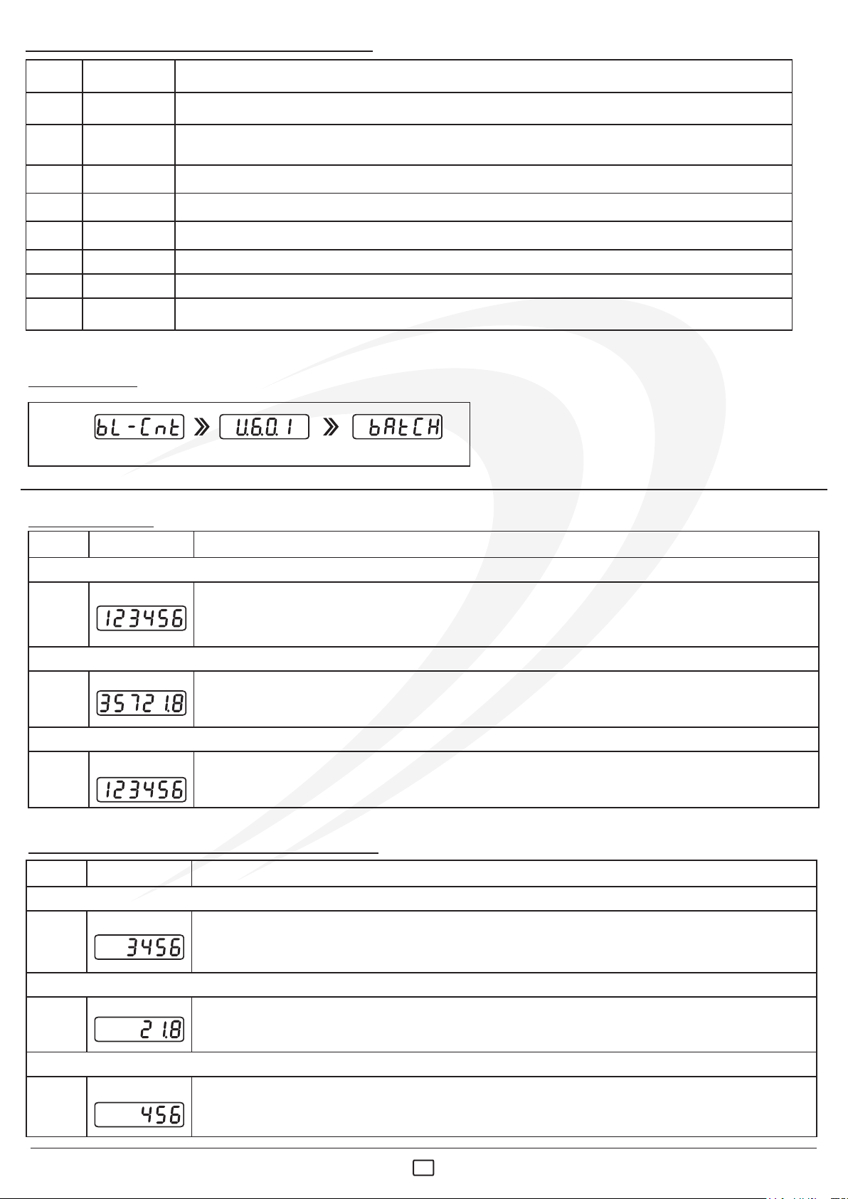
b) Output LED
i) T - Time LED
Display : 6 Digit 7 segment LED
b) Buzzer Output
Range : Ref. SET Mode
c) Status LED
Supply : 90 to 270 VAC
Sensor Supply : 12VDC (+10%) @ 30mA
Mounting : Panel
LED Indication : a) Mode LED
i)B - Batch, ii) L - Length, iii) P - Preset
i) 1 - Output 1, ii) 2 - Output 2
Outputs : a) Two 5Amp @ 230VAC Relay
Accuracy : 0.05% Full Scale
Memory : Non-Volatile (Flash)
Memory Retention: Up to 10 years
Housing : ABS Plastic
Humidity : 95% RN(Non Condensing)
Operating Temp. : 0 ~ 55°C
Mechanical : See Table:1 (On Page 2)
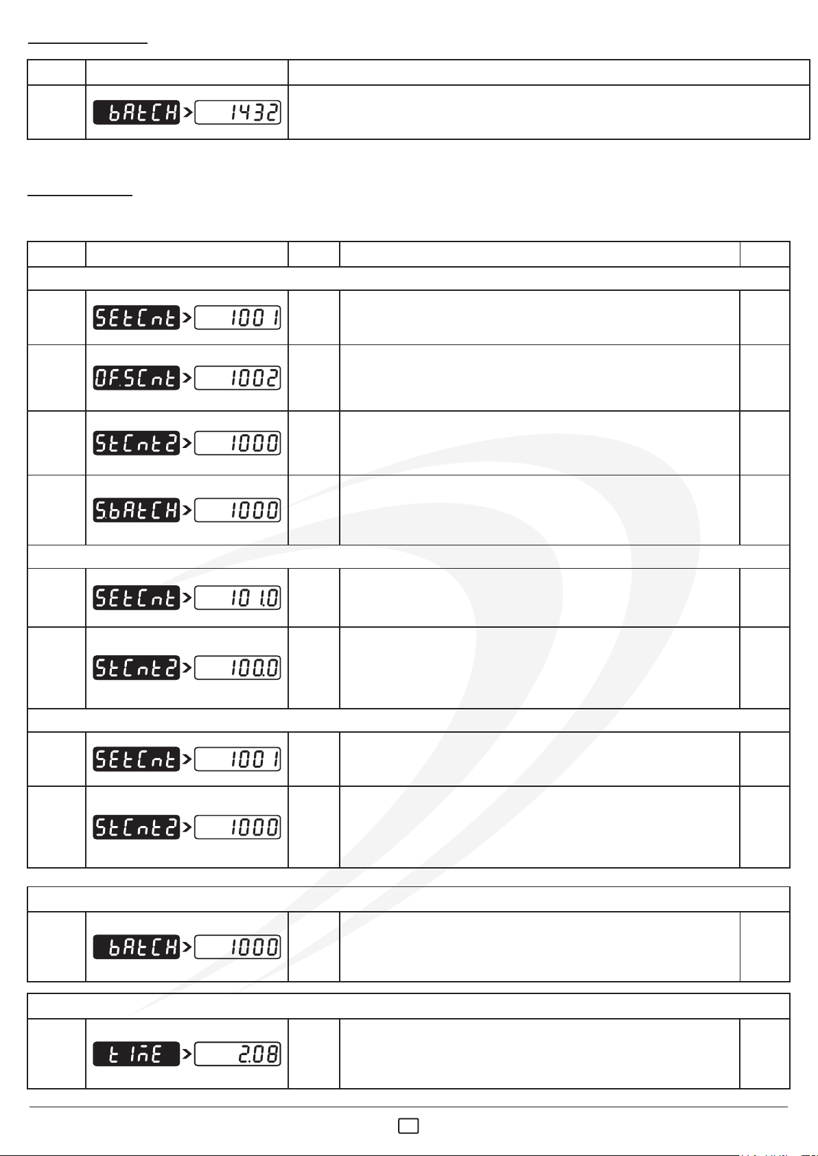
Operating Mode : a) Mode 1
Dimension
c) Preset Type
Configuration Parameters:-
b) Mode 2
Output 2 Function : a) As 2nd Set Point
c) As Auxiliary Output
Leading Zero : Enable / Disable (Selective)
Count Mode : a) Batch Type
Front Reset : Enable / Disable (Selective)
b) As Batch Output
Input Frequency : a) Very Low b) Low
c) Medium d) High
e) Very High
d) Output is Off
b) Length Type
User Lock : It can be Set Between 1 to 9999
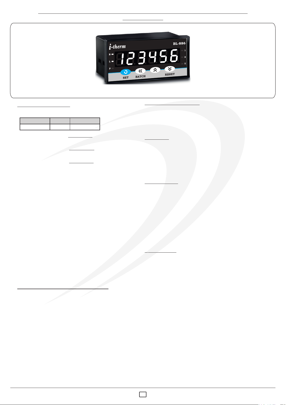
USER’S OPERATING MANUAL FOR BATCH, LENGTH & PRESET COUNTER
(Models :BL-886)
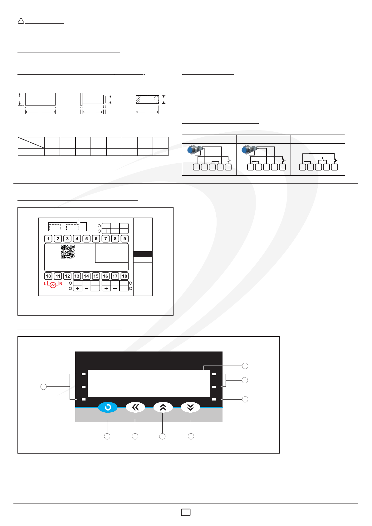
ELECTRICAL
vThe controller must be wired as per wiring diagram & it must
comply with local electrical regulation.
v The controller is generally part of control panel and in such a
case the terminals should not remain accessible to the user after
installation.
vThe controller in its installed state must be protected against
excessive electrostatic or electromagnetic interference s .
Ventilation holes provided on the chassis of the instrument are meant
for thermal dissipation hence should not be obstructed in the panel.
GENERAL
vCare must be taken not to connect AC supplies to low voltage
sensor input.
vThe Controller in its installed state should not be exposed to
carbon dust, salt air, direct sunlight or radiant heat.
vCircuit breaker and appropriate fuses must be used for
driving high voltage loads to protect the controller from any possible
damage due to short circuit on loads.
vTo minimize pickup of electrical noise, the wiring for low
voltage DC and sensor input must be routed away from high
current power cables. Where it is impractical to do this, use shielded
ground at both ends.
v The controller must be configured correctly for intended
operation. Incorrect configuration could result in damage to the
equipment or the process under control or it may lead personnel
injury.
MECHANICAL
vThe Controller in its installed state must not come in close
proximity to any corrosive/combustible gases, caustic vapors, oils,
steam or any other process by products.
This controller is meant for Batch & Length counter applications. It is
important to read the manual prior to installing or commissioning of
controller. All safety related instruction appearing in this manual must
be followed to ensure safety of the operating personnel as well as the
instrument.
vCircuit breaker or mains s/w with fuse (275V/1A) must be
installed between power supply and supply terminals to protect the
controller from any possible damage due to high voltage surges of
extended duration.
vThe Electrical noise generated by switching inductive loads might
create momentary Fluctuation in display, alarm latch up, data loss
or permanent damage to the instrument. To reduce this use snubber
circuit across the load.
SAFETY INSTRUCTION
vAmbient temperature and relative humidity surrounding the
controller must not exceed the maximum specified limit for proper
operation of the controller.
vThe controller should not be wired to a 3-Phase supply with
unearthed star connection. Under fault condition such supply could
rise above 264 VAC which will damage the controller.
1OIM BL-886 V1.2 Page 1 of 6
BL - 886
Display height (PV)
Model no.
White
Display Colour
0.56”
BL-886