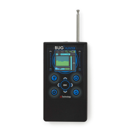
i4Technology BugHunter Professional BH-04 User manual

RF signal detector BugHunterтм Professional BH-04
User manual

CONTENTS
Introduction
1
Specification and operation
1.1
Application area
1.2
Technical features
1.3
Device components
1.4
Internal design and operation
2
Intended use
2.1
Operating restrictions
2.2
Before operating
2.3
Intended usage
3
Technical maintenance
4
Troubleshooting
5
Packaging and transportation

The User Manual includes key features, construction, operating principle, rules of operation (intended
use, technical maintenance, repair process, storage, and transportation) of "RF signal detector BugHunter
Professional BH-04" (hereafter referred to as the Product).
The Product is a device intended to detect radio transmitters in close proximity such as wireless "bugs",
wireless microphones, wireless spy cams, portable radio sets, working cellphones, signal suppressors, etc.
Attention!
Read this manual carefully in order to provide continuous, successful and safe operation of the pur-
chased Product.
Follow the rules, restrictions, and instructions contained in this manual to increase the lifespan
of the device and to use it more effectively.
The manufacturer's warranty will become invalid prematurely if the user of the equipment does
not follow the storage and transportation instructions.
Attention!
After storing the Product in a cold place or transporting it in wintertime, the device should be
kept at room temperature for two hours before operation.
Attention!
Please, make sure that the warranty sticker is not damaged. Check the delivery set in the article 1.3 of
this manual.

1. Specification and operation
1.1 The purpose and application area.
1.1.1 The Product allows users to monitor the radio signal strength at a frequency range of 10-8000
MHz and it can also be used to detect nearby field radio transmitters such as wireless "spy bugs", wireless
microphones, wireless spy cams, portable radio sets, working cellphones, signal suppressors, etc.
1.1.2 The Device is intended to be used at temperatures ranging from -10 to +40°С ( +10 to +104°F),
relative moisture below 98% at the temperature of +25°С (77°F), and at the atmospheric pressure of 84-
106,7 kPa.
1.1.3 The Product appearance is shown in Fig.1.
Fig.1 –The Product appearance
1.2 Technical features.
Table 1
Description
Value
Dimensions, mm, not more than (without receiving antennas)
130х80х16 mm
(5.12x3.15x0.63 in)
Weight
0,2 kg (7.05 in)
DC supply voltage (built-in Li-Pol battery)
From 3,5 to 4,2 V
Power consumption, max
0,6 W
Charger voltage
5 V
Working frequency range, (measurement channel ANT1)
From 10 to 2400 MHz
Working frequency range(measurement channel ANT2)
From 2400 to 8000 MHz
Responsivity (10..2400 MHz,measurement channel ANT1), max
-70 dBm
Responsivity (2400..8000 MHz,measurement channel ANT2), max
-55 dBm
Dynamic range (10..2400 MHz, measurement channel ANT1)
70 dB
Dynamic range (2400..8000 MHz, measurement channel ANT2)
55 dB
Responsivity of a frequency counter (100..2400 MHz, measurement channel
ANT1), max
-50 dBm

1.3 Device components.
Table 2
№
Description
Quantity.
1
RF signal detector BugHunter Professional BH-04
1
2
Antenna 10-2400 MHz (ANT1)
1
3
Antenna 2400-8000 MHz (ANT2)
1
4
Charger 5V 1A
1
5
Cable mini USB
1
6
Headphones
1
7
Shipping box
1
8
User manual
1
1.4 Internal design and operating.
1.4.1 The Product is a portable device that has an autonomous power supply. There are electronic mod-
ules and a battery inside of the case (item 1) which are made of aluminum alloy. The product has a TFT-
display (item 2), mini-USB connector (item 3) for the charger and connection to a PC, a jack (item 4) for
headphones,radio frequency connectorsfor removable antennas ANT1(item 5) and ANT2 (item 6).The Product
control is performed by a membrane keyboard with 10 push-buttons (item 7), On/Off buttons (item 8), and
volume control (item 9). A scheme of the main components is shown in Fig.2
Fig.2 –Scheme of the main components

1.4.2 Operating principle is based on measuring electric field power via broadband detector. The Prod-
uct has two independent high-sensitivity measurement channels (10-2400 MHz and 2400-8000 MHz) to cover
the entire possible frequency range where wireless "spy bugs" can be detected; a frequency counter to measure
periodic signal frequency; and the capability of identification of the most common data transfer protocols
based on the special analysis algorithms and digital signal processing. The built-in TFT-display shows the in-
formation as graphs of average and peak values, oscillograms and numerical values. It is also possible to turn
on vibration mode indication of exceeding the preset threshold by the average signal and vibration intensity
control. The demodulated sound signal is output through the built-in speaker or headphones, and the volume is
adjustable.
1.4.3 Operating modes of the Product are "Search", "Oscilloscope", "Security".
"Search" mode is used to detect and localize transmitters. In this mode the display shows graphs of aver-
age and peak values of measured signal strength. The bug search is performed using a visual assessment of
the current signal level. Presenting information in the form of a signal’s level change graph on the time curve
allows users to identify the nature of the signal and the type of transmitter. For more convenient localization
of transmitting devices and information analysis, sensitivity and scanning adjustments are provided.
The "Oscilloscope" mode is designed to display oscillograms (real-time strength level changes) with
adjustable scanning. Viewingthe oscillogram is convenient both for general analysisof the radio environment
and studying the nature of the signal of a particular localized transmitter to determine its type.
In "Security" mode, the Product adapts to the ambient background, switching to the standby mode and
further exiting from the standby mode upon detecting new signal sources. Logged alarm events can be set
by the user and are recorded in non-volatile memory. The Product can be connected to a PC in order to view
and analyze the alarm logbook.
2. Intended use.
2.1 Operating restrictions.
The product should be protected from mechanical damage, shock, dirt and liquids on its surface.
2.2 Before operating.
In order to prepare the device for operation you need to connect receiving antennas ANT1 and ANT2,
as shown in Fig.2.
2.3 Use of the Product.
2.3.1 On and off switching of the Product
To turn the device on, press and hold button (item 8) for 2 seconds in Fig.2. When the device turns on,
you’ll see the screensaver shown in Fig.3.
Fig.3 –Screensaver

Then the device switches to the "Search" mode and the screen will look like in Fig.4.
Fig.4 –Screen in the "Search" mode
To turn the device off, press and hold the button "item 8" for 2 seconds in Fig.2.
2.3.2 Operating modes –"Search", "Oscilloscope", "Security"
2.3.2.1 Switching between modes
The device always starts with the "Search" mode. The icon of the adjusted mode is displayed in
the top bar of the screen:
- "Search" mode;
- "Oscilloscope" mode;
- "Security" mode.
You can switch between operating modes by short-pressing the button . While switching to the "Se-
curity" mode, the notification will appear for 2 seconds (Fig.5).
Fig.5 - Switching to the "Security" mode
Then the screen turns off.
When the device is in the "security" mode, the notification appears on the screen periodically
(Fig.6):

Fig.6 - Notification in the "Security" mode
While changing the modes (by pressing this button ), the notification (Fig.7) appears on the screen
for 2 seconds. After it, the device will switch to the "Search" mode.
Fig.7 - Notification of switching to the "Search" mode
2.3.2.2 "Search" mode.
2.3.2.2.1 Graphical presentation of information in the "Search" mode.
"Search" mode is the main operating mode used to search for radio transmitting devices indoors. The main
elements of the "search" mode’s graphic interface are shown in the Fig. 8.
Fig.8 –Screen in the "Search" mode
The current level of radio signal strength is displayed in real time as a graph of peak values (item 1, red
color in the background) and average values (item 2, green color in the foreground). The current value is in

the right part of the graph, while the values are moving to the left, becoming obsolete.
Thus, graphs show the changing of the radio environment over time. These graphs are the main means
used to search for "spy bugs" via the visual assessment of the signal level and its change as the Product ap-
proaches/moves away from the transmission source.
Notification: Peak value graph (item 1) illustrates the impulse component and it is an equivalent of "im-
pulse" mode of searching devices (digital "bug" search mode). Average value graph (item 2) illustrates the
constant component and the realization of the "analog" mode (analog "bug" search mode). You can search
for the local maximum signal strength using any of these two graphs considering that the "impulse" mode,
i.e. peak value graph, is better when searching for digital "bugs".
Furthermore, there is additional information on the screen, which can be useful when searching for trans-
mitting devices:
- item 3 –frequency value for a steady periodic signal or designation of an identified data transfer protocol
(cl.2.3.2.2.2 Frequency (protocol) indication);
- item 4 (Е) –current values of peak and average signal strength in dB regarding zero;
- item 5 (Z) –stored values of zero level for peak and average radio signal strength (cl.2.3.2.2.8 Subtracting
background).
On the right part of the screen, the scales for adjusting the sensitivity (item 6) and the selection of the
vibration engagement threshold are displayed (item 7) (cl.2.3.2.2.3 Sensitivity and vibrate-mode indication
engagement threshold adjustment).
In the top line of the screen icons of settings and product status are located:
- items 8, 14 –selected measurement channel (cl.2.3.2.2.5 Measurement channel selection);
- item 9 –battery level;
- item 10 –current operating mode;
- item 11 –current time;
- item 12 –volume level;
- item 13 –vibrate-mode indication status (on or off).
2.3.2.2.2 Frequency (protocol) indication
The device provides an indication of the signal stable in time and also identifies and displays the most
common digital data transmitting standards such as GSM, DECT, Bluetooth, WLAN and 3G/4G (item 3
Fig.8).
Designations
- cell phones and GSM radio modules, data transmitting via GPRS, EDGE;
- cell phones and DECT radio modules;
- DECT BASE (DECT base stations);
- Bluetooth radio modules;
- wireless networks such as Wi-Fi, Zigbee, LoRA etc;
- cell phones and radio modules, working in data transfer mode on technology UMTS,
CDMA, LTE.
Note.
In case several different standard sources are operating simultaneously, the identification can be difficult, as
only one protocol can be displayed on the screen at the moment. It is recommended to turn off all known radio

transmission sources while searching.
2.3.2.2.3 Sensitivity and vibrate-mode indication engagement threshold adjustment.
You will need to adjust the device sensitivity within the searching process (scale item 6 in Fig.8) and (if
needed) the vibrate-mode indication engagement threshold (scale item 7 in Fig.8). To select the scale use
and buttons (in order to confirm selection press and hold the button for 2 seconds, with that the selected
scale marker will glow) and the adjustment is done by pressing the and buttons.
The sensitivity adjustment scale is active by default. You need to adjust the device sensitivity in the way
that selected graph will not "go into overdrive". The button increases the sensitivity (to display signals
that have a weaker amplitude). The button decreases sensitivity in order to display stronger signals.
The device supports automatic sensitivity adjustment. To perform this in the search mode, press and hold
the button for 2 seconds. Automatic adjustment is performed according to the average signal strength level
(graph item 2 in Fig.8).
Vibrate-mode indication engagement threshold adjustment is performed in accordance with the average
signal strength level, displayed in real time on the scale (item 7, Fig.8) in the device’s full dynamic range,
without a reference to selected sensitivity level. This scale can be used for the overall assessment of the radio
environment at the current moment.
2.3.2.2.4 Scanning adjustment.
The graph items 1 and 2 of Fig. 8 display radio environment changes during the last 7.5 seconds by default.
This time interval can be increased or decreased if necessary. Available values are as follows: 2.5 sec.; 4.5 sec.;
7.5 sec.; 12 sec. and 22 sec. Scanning adjustment is performed by short-pressing the buttons and . After
switching, the current scanning value is briefly displayed in the lower left corner of the screen.
2.3.2.2.5 Measurement channel selection.
Measurement channel selection (ANT1, ANT2, ANT1+ANT2) is performed by successively pressing the
button . The icons of the selected measurement channels in the upper part of the screen are highlighted.
The channel ANT1 is more sensitive and is suitable for searching the vast majority of bugs and other radio
transmitting devices, including analog radio microphones and devices based on cellular radio modules, etc.
The measurement channel ANT2 is faster and of higher frequency. First of all, it is designed to search for
devices operating at 2.4 GHz and above (these can be Wi-Fi / Bluetooth 2.4/5 GHz modules, analog video
cameras 5.8 GHz and other modern devices).
Note.
1. For express analysis, the measurement channels ANT1 and ANT2 can be shared, however, it should be
noted that all capabilities of the high-sensitive channel ANT1 will not be used in this case, since product sen-
sitivity will be limited according to the characteristics of the channel ANT2.
2. The advantage of channel ANT2 is high speed (response to nanosecond pulses) and operation in the
microwave range of up to 8 GHz. At the same time, it is also applicable to searching for transmitters with a
lower operating frequency than 2.4 GHz, both digital and analog, but less sensitive than the channel ANT1,
and therefore less suitable when searching for low-power (microwatt) analog transmitters.
2.3.2.2.6 Use of sound indication.
The acoustic control function is provided in the Product - the demodulated sound signal is output through
the built-in speaker. The sound volume can be adjusted with the help of buttons (item 9 Fig. 2). For hidden
control, the volume can be lowered to a zero level or headphones can be used.
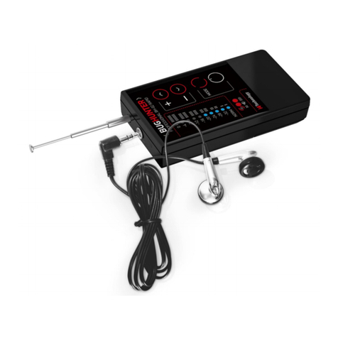
2.3.2.2.7 Use of probing signal.
Special probing sound signal can be used in the Product. To activate this function near the intended place
of installation of the transmitting device, you must press the button ; the Product will beep (while pressing
the button the Product switches to the mode of constant probing signal generation, which is turned off by
pressing the same button again). The listening device catches and transmits this sound. In certain cases (for
example, if an AM-modulated radio microphone is installed), the demodulated sound reproduced by the Prod-
uct will correlate with the probing sound signal and have a clear correlation with it. If the Product determines
that the correlation between the probing sound signal is being produced by it and the demodulated received
radio signal, the icon in the lower left part of the screen flashes in white. The presence of the correlation
can also be controlled by ear; it is advisable to use headphones.
In addition, this function can be useful in the event that the installed transmitting devices are activated only
during the sound recording of the room and at another time there is no radio broadcast.
2.3.2.2.8 Interference subtraction.
The product has an interference subtraction function. When you press the button , the Product remem-
bers the current radio signal level (item 5, Fig. 8) and further displays the peak and average values (item 1, 2,
4, Fig. 8) of the signal’s strength regarding the memorized level. The memorized zero level will be displayed
in the area Z of numerical values (item 5, Fig.8). You should press the button again to turn off the Inter-
ference subtraction function.
2.3.2.2.9 Recommendations for using the Product in the "Search" mode.
-Before starting the search, switch off all radio-emitting devices if possible (Wi-Fi, smartphones, tablets,
computers, radiophones, etc.). It simplifies the search for eliminating excessive interference.
-Do not forget that a counterpart canhear you and, in certain cases, can break the connection or deactivate
the bug remotely, making further searching senseless. Therefore, do not discuss your actions out loud and use
the probing signal function with caution.
-Prepare the Product for use and turn it on. The Product will automatically adjust the level of sensitivity.
The screen will display the graphs of the peak and average signal values, as well as one of the digital data
transfer protocols that have been identified. Select the measurement channel ANT1 for examining the prem-
ises for the presence of analog bugs (radio speakers, cameras) and the most common digital devices based on
2G / 3G / LTE communication modules (GSM bugs, 3G video cameras, etc).
-Probable installation places for bugs and spying devices include: cavities and slots in baseboards, walls,
and behind radiators, in addition to hard-to-reach places on closets, ledges, hollow ceilings, ventilation shafts,
furniture, household items, flowers, car dashboards, seats, etc.
-Start walking around your room, holding the device at a distance of 0.3 –0.5 meters (0,98 –1.64 ft)
from the researched surface (walls, furniture etc). Monitor the visual change of radio signal strength, focusing
mainly on the green graph of average values. If an increase in the signal strength is clearly visible on the
product screen and the graph goes "into overdrive", press and hold the button for 2 seconds in order to
adjust the sensitivity automatically (or manually reduce the sensitivity of the product using the button ).
Examine the place where the source of the radio signal is supposed to be from a closer distance. Repeat these
steps until a source of signal emission has been identified.
-Analog transmitters search method: after the automatic sensitivity adjustment, you can decrease it by
two levels. Then search the supposed "bugs" locations from a distance of at most 0.2 meters (0.66 ft). If the
signal maximum appears, reduce sensitivity further and search the location for the closer distance of 5 - 10
cm (1.97 –3.94 in) to find the location of the signal source more accurately. Fig.9 illustrates the typical view
of the screen while approaching the radio transmission source if this method is used:

Fig.9 - Signal strength level increasing when approaching an analog transmitter
-If the signal is periodic, the device will display its frequency in MHz.
-If there is a strong enough and permanent enough signal level all over the room, it may mean that there
is a powerful external source of radio transmission nearby (cell phone tower, strong Wi-Fi access points in
the next rooms, etc). In this case, try to switch on all device’s filters, as this will significantly reduce the in-
terference of such sources on the search process.
-Use the sound indication mode when searching. In most cases, the demodulated sound produced by the
device is very informative (in the immediate vicinity of radio microphone, the nature of the sound changes
significantly - it completely goes off, or, conversely, sounds can be clearly noticeable; GSM / GPRS trans-
mitter can be easily identified by the characteristic "cod", Wi-Fi / Bluetooth transmitters - by "rustling" or
frequent "knocking"). Earphones are recommended for acoustic control.
-If there are spikes and valleys, in addition to the spaces on the green graph of average values as shown
in Fig.10, then there is a high probability of an operating digital transmitter. The digital character of the de-
tected signal is also defined by obvious transmission/pause intervals on the peak values graph and the higher
amplitude of peak values, compared to the average ones, as shown in Fig.10.
а) 2G/3G transmitter signal during talktime
b) Wi-Fi signal of equipment
Fig. 10 –Graphs in the coverage area of digital transmitters
In this case, decrease sensitivity by pressing the button to the level where the red graph of peak val-
ues doesn’t "go into overdrive". Continue your search while considering the peak values graph.
Repeat the search, using measurement channel ANT2 to identify devices working at frequency 2.4 GHz
and above, such as Wi-Fi/Bluetooth transmitters of 2.4/5 GHz, analog cameras 2.4/5.8 GHz, etc. Paying at-
tention to the constant component of the Wi-Fi signal and Bluetooth devices, as a rule, is weak. Instead, a
search should be made focusing on the peak values of the signal (red graph).
2.3.2.3 "Oscilloscope" mode
2.3.2.3.1 Graphic presentation of information in the "Oscilloscope" mode
"Oscilloscope" mode is an auxiliary Product’s operating mode intended for displaying radio signal oscil-
lograms. The Product’s screen in this mode is shown in Fig.11.

Fig. 11 –The screen in the "Oscilloscope" mode
The main purpose of the oscillogram is to inform the user about the form of the radio signal and the nature
of its change over time in order to identify the type of transmitter.
2.3.2.3.2 Measurement channel selection.
Measurement channel selection (ANT1, ANT2) is performed in the same way as in "Search" mode: by
successively pressing the button . The color of the oscillogram corresponds with the color of the icon of
the selected channel in the upper line of the screen. When both measurement channels (ANT1 + ANT2) work
together, two waveforms are displayed simultaneously.
2.3.2.3.3 Scanning adjustment.
The product provides one with the ability to change the horizontal and vertical scanning buttons and
. The horizontal scan values are 200 µs, 500 µs, 1 ms, 5 ms and 10 ms (per grid division). After switching
the current value of the horizontal scan is displayed in the lower left corner of the screen for a short time.
2.3.2.3.4 Oscillogram "freezing" and "unfreezing".
You can stop the signal rendering on a screen for a detailed signal form analysis bypressing the button.
You then "freeze" the current oscillogram on the screen. The renewal of the display ("unfreezing") is repeated
by pressing the same button.
2.3.2.3.5 Oscillograms of some signals.
Typical oscillograms of signals of some common types of radio transmitting devices are shown in Fig.12
a) Analog transmitter b) GSM c) Wi-Fi
Fig.12 –Typical oscillograms
2.3.2.4 "Security" mode.
The device is switched to the "Security" mode when there are no unknown emissions in the room
and the implicit control of the situation is needed, such as during negotiations. In addition, this mode can be
used for a room monitoring in the user’s absence to register new radio transmission sources, such as re-
motely controlled devices, transmitters with the function of delayed transmission, etc. You can view the
alarm logbook when the product is connected to a PC in accordance with cl.2.3.4.

When switched into "security" mode, the device assesses its surrounding radio environment and
memorizes the signal level. Then the device screen turns off. If some new source of signal appears, a cell
phone turns on to transmit data or a "spy bug" activates after a long pause in data transmission, etc, the de-
vice will alarm you about this - the screen will turn on, the device will vibrate and produce a sound in ac-
cordance with current Product settings. When the alarm cause is removed (the cell phone is switched off or
removed from the room, or a "bug" is deactivated), graphic, acoustic and vibrate-mode indications will auto-
matically switch off, and the product will go back to sleep mode, continuing to register further events.
The adjustment of registered alarm events is done by the user in accordance with cl.2.3.3.5.
Note.
1.The opportunity to adjust the device is limited in "Security" mode. To make adjustments (vibration
intensity, registered alarm events, etc) you need to switch the device to the "Search" mode or "Oscilloscope"
mode.
2. For long operating hours while in the "Security" mode, use external power.
2.3.3 User settings.
In the "Search" mode or "Oscilloscope" mode for the device settings, press the button. Themainmenu
is displayed on the screen (Fig.13).
Fig.13 –The main menu
To exit the main menu, press the or buttons.
2.3.3.1 Date settings.
While in the main menu as shown in Fig.13, select "Date" by pressing the and buttons and confirm
the selection by pressing the or buttons. The date setting screen appears Fig.14:
Fig.14 –Date settings
Select the date, month and year by pressing the buttons and and changing values by pressing
and if necessary. To save settings and exit to the main menu press To exit without saving, press .
2.3.3.2 Time settings.
While in the main menu (Fig.13), select "Time" by pressing and and confirm the selection by

pressing or . The time setting screen appears as per Fig.15:
Fig.15 –Time settings
Select hours or minutes by pressing the and buttons or change values by pressing the buttons
and if necessary. Press to save settings and return to themain menu. To exit without saving the settings,
press .
2.3.3.3 Brightness.
While in the main menu (Fig.13), select "Brightness" by pressing and and confirm the selection by
pressing or .The screen brightness settings will be displayed (Fig.16):
Fig.16 –Brightness
Select the required brightness level by pressing and . Press to save settings and return to the
main menu. To exit without saving press .
2.3.3.4 Vibration level adjustment.
Being in the main menu (Fig.13), select "Vibration" by pressing and and confirm the selection by
pressing or . A sub-menu will appear (Fig.17):
Fig.17 –Vibration settings
Select the required vibration level by pressing and (the higher the level, the stronger vibration in-
tensity) or item "Turn off vibration". Confirm (if changes are necessary) the selection of another level by press-
ing the button, then the selected level will glow red. By pressing users can return to the main menu in
order to continue adjustment or they can exit the operation mode by pressing .

2.3.3.5 "Security" mode settings.
While in the main menu (Fig.13), select "Security mode" by pressing the and buttons and confirm
the selection by pressing or . A sub-menu will appear (Fig.18):
Fig.18 –"Security" mode settings
This group of parameters determines the need for alarm engagement (and its registration in the logbook)
when certain events occur. Active (enabled) items are highlighted in red.
2.3.3.5.1 Signal level.
This setting increases the radio signal strength level with a minimal increase regarding an interference level
(measured during switching to "Security" mode), leading to alarm engagement.
Being in the sub-menu of "Security" mode settings, select and activate (or deactivate) item "Signal level"
(if necessary) by pressing the button. If it is necessary to change the relative threshold signal level (10 dB
by default), thenpressthe button. The numerical value selection in dB will be activated, as shown in Fig.19.
Fig.19 –Relative threshold signal level change for alarm engagement
Select a required value ranging from 1 to 55 dB by pressing the and buttons. Confirm the selection
by pressing .
2.3.3.5.2 Frequency capture.
This parameter determines whether the frequency capture is an alarming event. While in the sub-menu of
the "Security" mode settings, if necessary, select and activate (or deactivate) the "Frequency capture" item by
pressing the button .
2.3.3.5.3 Protocol.
This parameter determines whether the protocol identification is an alarming event. While in the sub-menu
of the "Security" mode settings, if necessary, select and activate (or deactivate) the "Protocol" item by pressing
the button .
If it is necessary, turn on or off separately identified protocols by pressing the button. A sub-menu of
the separate protocol selections will appear (Fig.20).

Fig.20 –The inclusion of separately selected protocols in the list of alarm events
Being in this sub-menu, you can select and activate (or deactivate) separate data transfer protocols by press-
ing . Activated protocols are highlighted in red.
2.3.3.5.4 Duration.
This is the setting for the minimum event duration, the exceeding of which triggers an alarm. Events of
shorter duration will not be registered.
Being in sub-menu "Security" mode settings, if necessary, activate (or deactivate) "Duration" items by
pressing the button. Ifit is necessaryto change the time interval (5 sec by default), then pressthe button.
Numerical value selection will be activated in seconds, as shown in Fig.21.
Fig.21 –Minimum alarm duration setting
Select the necessary value ranging from 1 to 60 seconds by pressing the and buttons. Confirm the
selection by pressing .
2.3.3.6 Time Setting Displays.
While in the main menu (Fig.13), select the"Display off" item by pressing the and buttons and
confirm the selection by pressing the or button. A sub-menu will appear (Fig.22):
Fig.22 –The display of time settings
Select the necessary timeout period, after which the Product screen will be turned off to save battery power if there
is no activity by pressing and buttons, or "Always on". Confirm (if changes are necessary) parameter

selection by pressing , then the selected parameter will be highlighted in red. By pressing , the users can re-
turn to the main menu to continue adjustment or they can exit to the operation mode by pressing .
Note. In the "Security" mode, this setting is ignored.
2.3.3.7 Auto-shutdown time setting
While in the main menu Fig.13, select the"Auto-shutdown" item by pressing the and buttons and
confirm the selection by pressing or . A sub-menu will appear in Fig.23:
Fig.23 –Auto-shutdown time setting
Select the necessary timeout period, after which the Product screen will be turned off to save battery
power if there is no activity by pressing and buttons, or "Always on". Confirm (if changes are neces-
sary) parameter selection by pressing , then the selected parameter will be highlighted in red. By pressing
users can return to the main menu in order to continue adjustment, or they can exit to the operation mode
by pressing .
Note. In the "Security" mode, this setting is ignored.
2.3.4 Connection to PC.
When connected to a PC over the current image, a dialog box is displayed on the screen with the choice:
"Charge only" / "View logs", as shown in Fig. 24. Using the buttons and , you can make a selection and
confirm the selection made by pressing .
The Product continues its operation when "Charge only" is selected, while recharging the built-in battery
from the USB port of the PC.
To generate a report, select "View logs".
Fig.24 –Selection menu when connected to a PC
The operating system will identify the product as a standard flash drive (an image of a flash drive will
appear on the screen). A file in the form "BH-04-2018-11-30-23-33-45.pdf" will be generated on the drive,
available for viewing by any application intended for viewing PDF files (Acrobat Reader, etc). Inside the file,
a list of alarm events from the product log will be displayed as a table, as shown in Fig.25:

Fig.25 –Report (alarm logbook)
Attention! In the log-viewing mode, using the product in the main operation modes ("Search", "Oscillo-
scope", "Security") is impossible!
Attention! After the file is generated, the internal alarm logbook will be cleared when connecting a new
file with new data to a PC. Therefore, for further analysis, the file must be copied to another drive with the
help of the operating system(copy) or viewing program (File-Save as…).
3. Technical maintenance.
3.1 Keep the product clean. Periodically remove the dust with a dry and clean cloth.
3.2 Keep the product free from strokes and mechanical damage.
3.3 Recharge batteries regularly. The power level is indicated by the filling level and the
color of the battery sign located in the top bar of the screen.
3.4 You should charge the batteries as follows:
Plug the supplied charger to the device jack using supplied cable (item 3 Fig.2). If the device is on while
charging, the battery icon on the screen becomes animated. If the device is off while charging, the ani-
mated screen saver is displayed on the screen (Fig.26).
Fig. 26–Charging when the device is off
4. Possible faults.
Troubleshooting is shown in Table 3
Table 3
Failure
Possible causes
Remedy
The device is turned on, but there is no
image on the screen
Batteries are fully
discharged
Recharge the battery
Device is defective
Take the device to a service

center
5. Package and transportation.
Every Product in the delivery set (see Table 2) is packaged in an individual corrugated cardboard box. Mov-
ing the contents of the box is not allowed.
Packaged products can be transported by train or by trucks (in covered trucks or containers) or by air
transport in pressurized modules. During transportation, the packaged products should be protected from the
direct impact of atmospheric condensation and solar radiation.
Transportation terms:
- Environmental temperature: from -50 to 50°С (from -58 to 122 °F);
- Relative humidity: below 95 % at temperature 25°С (77 °F);
- Atmospheric pressure: from 84 to 107 kPa (from 630 to 800 millimeters of mercury);
The requirements specified on the package warning labels must be strictly observed during
loading and transportation.
This manual suits for next models
1
Table of contents
Other i4Technology Security Sensor manuals

i4Technology
i4Technology Bughunter dVideo BDV-01 User manual

i4Technology
i4Technology Bughunter dVideo User manual

i4Technology
i4Technology BugHunter Professional BH-03 Expert User manual

i4Technology
i4Technology BugHunter Professional BH-03 Expert User manual

i4Technology
i4Technology BugHunter Professional BH-02 Rapid User manual

i4Technology
i4Technology BugHunter Professional CR-01 User manual

i4Technology
i4Technology Bughunter TM DVIDEO NANO User manual

i4Technology
i4Technology BugHunter Professional CR-01 User manual