IACER BIO EMG User manual

USER MANUAL
MNPG213-00Edition14/01/2016
BIO EMG
Read the user manual carefully
before using the BIO EMG.

I.A.C.E.R. S.r.l. 2 MNPG213-00

I.A.C.E.R. S.r.l. 3 MNPG213-00
CONTENTS
1. GENERAL DESCRIPTION 4
2. CONTENTS OF BIO EMG KIT 6
3. INTENDED USE 6
4. WARNINGS 7
5. MEANING OF THE SYMBOLS ON THE BIO EMG AND IN THE
USER MANUAL 8
7. HOW DOES BIO EMG WORK 16
8. MUSCLES TO BE MONITORED POSITION OF ELECTRODES 19
9. CHARGING THE BATTERY 19
10. USING THE MOBILE APP 19
11. MAINTENANCE AND STORAGE OF BIO EMG 20
12. TECHNICAL FEATURES 21
13. WARRANTY 22

I.A.C.E.R. S.r.l. 4 MNPG213-00
. GENERAL DESCRIPTION
What is BIO EMG: this is a biofeedback instrument based on the analysis of surface
electromyographic signals (sEMG). The device is designed to detect signals generated by
muscles in the human body and provide feedback from two channels.
What is BIO EMG used for: the user can record the MVC (maximal voluntary contraction)
generated by a muscle. Subsequently, by setting the MVC values in percentage, the patient can
do exercises under total control of the force expressed. There are two Working Modes: UNDER
THRESHOLD and MAINTAIN TARGET.
Reference Contraction Mode (MVC)
Measures the maximum voluntary contraction (MVC) representing the reference value required
to set the Target or under Threshold working mode. In this mode, the assistant/therapist can
detect the force expressed by a muscle/muscle group in the same patient at different times. In
this way you can get an indication on the trend of the force expressed at different times.
Another application involves the measurement before and after a session of osteopathy to
evaluate the effects. In any case, these are NOT diagnostic measurements, but only indicative
of a trend.
According to the different targets set by the assistant or the therapist, the following two modes
can be used: UNDER THRESHOLD and MAINTAIN TARGET.
When to use the Under Threshold mode
This mode should be used when you intend to perform contractions/exercises below a certain
threshold referred to the MVC value previously measured. For example, when you want the
patient to contract a certain muscle without overworking the same, for a set number of times.
Or, when you want to monitor the activation of a muscle during work or sports activities: for
MAIN MENU
Ref. Contraction
Relative Feedback
Working Mode
Settings
Save/Load Settings

I.A.C.E.R. S.r.l. 5 MNPG213-00
example, you want muscle activation to be maintained below a certain threshold (the patient is
alerted each time the threshold is exceeded, being aware of this and focusing on muscle
relaxation). See how to use the
Under threshold
working mode on page 17.
When to use the Maintain Target mode
This mode guides the patient to perform contractions until reaching a Target which must be
maintained for a variable period of time (2-5 seconds). This mode promotes the recovery of
force but most of all patient gesture control. In particular, by reducing the Target Error you
will have an increase in difficulty of the exercise and, therefore, an increase in the control
ability of the patient. See how to use the
Maintain targe
t mode on page 16.
MAIN APPLICATIONS
•Neurological rehabilitation (provides the patient and the therapist quantitative and
qualitative indication on the muscles monitored). In this way, it provides a quantitative support
that helps the patient activate individual muscles when his/her control ability is limited.
•Functional rehabilitation: it helps the patient and the therapist to qualitatively measure the
degree of muscle activation, particularly when used in TARGET mode. The aim is to bring
awareness about the activation of a certain muscle or action to be taken, providing control over
the execution of the gesture.
•Quantitative measurement. Provides clear indications about muscle activation degree. For
example before and after an osteopathic manoeuvre, to measure the force of agonist or
antagonist muscles next to the treated area. It can also be used in case of muscle hyper-
activation to offer the patient the possibility to control hyper-activations.
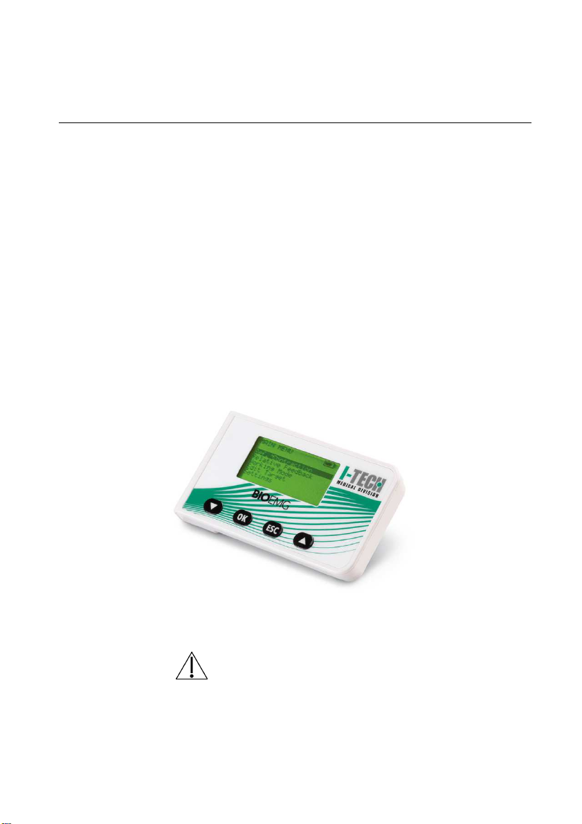
The biofeedback is both visual (display) and acoustic (internal buzzer).
Bioelectric signals are measured in single differential mode with bipolar electrodes. These
signals are amplified, filtered, converted to digital signals and then shown on the display
(stored in the internal memory, if installed).

I.A.C.E.R. S.r.l. 6 MNPG213-00
2. CONTENTS OF BIO EMG KIT
•1 BIO EMG amplifier (device).
•1 cable for connecting the reception and earth electrodes.
•1 USB charging cable.
•1 110/240V battery charger with USB plug
•4 earth electrodes.
•6 concentric electrodes for signal reception.
•1 user manual BIO EMG.
3. INTENDED USE
The BIO EMG system allows non-invasive recording of surface electromyographic signals
(sEMG) received by electrodes placed on the skin. The device is suitable for training and
recovery of muscles after injury; it is useful for quantitative and qualitative definition of
muscular activity. To use the BIO EMG device properly you must read the user manual.

I.A.C.E.R. S.r.l. 7 MNPG213-00
Contraindications
BIO EMG is a battery powered device and has no particular contraindications.
Side effects
No significant side effects known. All parts that come into contact with the patient are
made of biocompatible materials. Slight allergic skin reactions (such as rash) may appear;
such reactions are minimised due to short duration of electromyographic signal
acquisitions. No form of energy is transferred to the human body! The device is only
meant to capture electrical signals from the muscles. The device has no diagnostic
purposes. It is only intended to monitor physical exercise by assessing the degree of
muscle activation and comparing the degree of muscle activation at different times.
4. WARNINGS
The use of BIO EMG is forbidden under the following conditions:
•While using surgical equipment, shortwave and microwave.
•In mentally impaired patients, unless assisted by a professional rehabilitation
therapist.
•Whenever the equipment is damaged.
•In the vicinity of flammable substances (especially flammable liquids and gases) or
in environments with high concentrations of oxygen.
•In patients who use “life-saving” devices that may be adversely affected such as
pacemakers or others, unless assisted by a professional rehabilitation therapist.
Please observe the following precautions:
•Use exclusively the electrodes supplied by the manufacturer: BIO EMG is
guaranteed to output the rated performance only if used with the electrodes
supplied by the manufacturer.
•Immediately contact the manufacturer if foreign materials get inside the device
(liquid, powder, etc.). Should BIO EMG be subjected to impacts (like a fall to the
ground, etc.), make sure that any crack or any other type of damage of the casing
has damaged the device. Should you have any doubts, please contact the
manufacturer.

I.A.C.E.R. S.r.l. 8 MNPG213-00
•Incorrect measurement may be encountered if the device is being used in the
presence of electromagnetic sources (for example strong electromagnetic fields).
The presence of interference within the signals can be easily observed by qualified
personnel. For this reason we recommend you always use the device in “clear”
environments, free from electromagnetic disturbances, away from power supplies,
power outlets, and other electronic devices that may interfere with sEMG signal
reading.
•
The use of BIO EMG is allowed to persons properly trained on how to use the same
by reading the user manual.
5. MEANING OF THE SYMBOLS ON THE BIO EMG AND IN
THE USER MANUAL
The four front keys allow the user to completely control the device and all its functions.
The keys of the instrument allow the user to access and exit the various submenus, edit
parameters, start and stop the acquisition process.
Each time you press a key, the instrument emits a beep indicating that the keystroke was
recognised.
The "arrow up" and "arrow down" buttons allow the user to select the items of the
menus or increase or decrease the value of a parameter when the latter is being edited.
The "OK" button, depending on the state of the device, allows you to enter the selected
menu, edit the value of a parameter, and confirm the new value entered.
The "ESC" button, depending on the state of the device, allows you to exit the menu
selected and exit the parameter editing window.

I.A.C.E.R. S.r.l. 9 MNPG213-00
Multifunction keys, selection of menu options, selection of
parameters and setting of desired values.
Multifunction key that allows you to confirm the selected
parameter and open the parameter setting window.
Multifunction key that allows you to exit the menu, and the
parameter setting window.
SWITCHING ON THE EMG BIO

I.A.C.E.R. S.r.l. 10 MNPG213-00
6. MENU STRUCTURE
TABLE 7.1 provides a summary description of BIO EMG system menu.
Mode Description
Reference Contraction
When selected with the OK button, it records the
reference contraction level, the MVC (maximum
voluntary contraction). Subsequent measurements
will take this value as a reference for the working
mode. Once you have made the acquisition, press
ESC to return to the main menu.
Relative Feedback
After detecting the MVC, in the previous step, this
function activates the audible and visual feedback. It
will be a percentage of MVC. The therapist may ask
the patient to perform all contractions at 50% of the
MVC.
Working
Mode
Under
Threshold
This mode ensures that a certain threshold for each
individual contraction is not exceeded (i.e. 65% of the
MVC).
Target
This mode provides maintaining a level of contraction
as a percentage of MVC. For example, 40% of the
MVC with a margin of error (target error) that can be
set in the SETTINGS mode. The higher the margin
the easier the exercise, the lower the margin the
higher the difficulty.
Settings
Channel
Settings
It allows you to enable or disable the channels (CH1
only, CH2 only, both), set the display scale (GAIN),
and the alarm threshold for the Under Threshold
working mode.
Edit Target Allows you to set the level of contraction to maintain
in TARGET mode
Target Error
Allows you to change the tolerance of the level of
contraction set in TARGET mode.
Save/load Settings Saves the current settings or loads a previously
saved set of settings. The device can store up to 4
programs.
TAB. 7.1 Summary of settings of the pages displayed by BIO EMG

I.A.C.E.R. S.r.l. 11 MNPG213-00
FIG. 7.1 to the right shows the page displayed if you select the recording mode of
maximum voluntary contraction (MVC).
FIG. 7.1: Reference Contraction Function
FIG. 7.2 to the right shows the two pages displayed depending on whether you select
Relative Feedback Under Threshold (A) mode rather than the Maintain Target (B) mode.
A
B
FIG. 7.2: Relative Feedback function page: Under Threshold (A), Maintain Target (B).
MAIN MENU
Ref. Contraction
Relative Feedback
Working Mode
Settings
Save/Load Settings
MAIN MENU
Ref. Contraction
Relative Feedback
Working Mode
Settings
Save/Load Settings
FEEDBACK
I
II
Th1 Th2
FEEDBACK
Targ:50% Error: 5%
Rf1: __uV Rf2: __uV
REF. CONTRACTION
I
II
CH1:
µ
V
CH2:
µ
V

I.A.C.E.R. S.r.l. 12 MNPG213-00
FIG. 7.3 to the right shows the pages displayed when you enter the Working Mode
selection mode.
FIG. 7.3: Working Mode operating mode page
FIG. 7.4 shows the Settings function pages. FIG. 7.5 to the right shows the page
displayed when you enter the Target setting mode. FIG7.6 shows the Target Error setup
page. FIG. 7.7 to the right shows the channel setup page.
FIG. 7.4: Settings function pages
FIG. 7.5: Edit Target function page
OK
OK
SETTINGS
Channel Settings
Edit Target
Target Error: 3 %
TARGET
Target = 50 %
MAIN MENU
Ref. Contraction
Relative Feedback
Working Mode
Settings
Save/Load
Settings
WORKING MODE
oUnder threshold
•Maintain Target
SETTINGS
Channel Settings
Edit Target = 50% MVC
Target Error: 3 %
MAIN MENU
Ref. Contraction
Relative Feedback
Working Mode
Settings
Save/Load Settings

I.A.C.E.R. S.r.l. 13 MNPG213-00
FIG. 7.6: Target Error function page
FIG. 7.7: Channel Settings function page
SETTINGS
From this menu you can change the settings of the instrument. In particular, the items
available in the menu are listed below.
Channels Settings
This function allows you to change the settings of each channel. Use the “arrow keys” to
select the desired parameter, then press the OK button to vary the parameter. In
particular, for every channel you can change the status (ON or OFF), you can vary the
display gain (x 1, x 2, x 4, x 8) and you can also vary the threshold for the Under
Threshold mode, gradually by 2% .
SETTINGS
Channel Settings
Edit Target = 50% MVC
Target Error: 3 %
CHANNELS SETTINGS
| Ch1 Ch2
-------------------
State | ON ON
Gain | x2 x4
Thres | 50% 50%
SETTINGS
Channel Settings
Edit Target
Target Error: 3 %

I.A.C.E.R. S.r.l. 14 MNPG213-00
FIG. 9.6: Page for selecting the display scale Firmware Gain Settings.
Edit Target
This parameter is used to adjust the offset from maximum and minimum threshold set by
the BIO EMG system for the Relative Feedback Maintain Target mode. The target
value can be set from 0 to 98%, gradually by 2%. The "arrow up" and "arrow down"
buttons are used to change the value of the target offset. The "OK" button allows you to
save the new value and return to the previous page automatically, while the "ESC"
button allows you to return to the previous page without saving the value set.
FIG. 9.5: Example of LCD display visualisation during the Edit Target function.
CHANNELS MENU
| Ch1 Ch2
-------------------
State | ON ON
Gain | x2 x4
Thres | 50% 50%
TARGET
Target = 50 % MVC

I.A.C.E.R. S.r.l. 15 MNPG213-00
Target Error
This value determines the accuracy, as a percentage, at which the level of contraction set
must be maintained. Selectable values range from 1 to 9%: 1% maximum control of the
patient, 9% at the beginning of a period of recovery/rehabilitation.
Save/Load Settings
This feature allows you to save or load previously saved or set parameters.
FIG. 9.9: Page for choosing whether to save or load previously saved or set parameters.
FIG. 9.10: Page with details on saving and loading of parameters previously set
or saved.
SAVE & LOAD
Save Curr. Settings
Load Settings
SAVE SETTINGS
Position 1
Position 2
Position 3
Position 4
LOAD SETTINGS
Position 1
Position 2
Position 3
Position 4
SETTINGS
Channel Settings
Edit Target
Target Error: 3 %

I.A.C.E.R. S.r.l. 16 MNPG213-00
7. HOW DOES BIO EMG WORK
Use in TARGET mode
1. Connect the cable to the device that will turn on
2. Connect the button electrode near a muscle being monitored
3. Connect the electrode sEMG of CH1 (the one with the black ring) above the
middle of the affected muscle. If you need to monitor 2 muscles, use both
channels
4. Select Working Mode and press OK
5. Select MaintainTarget and press OK, then ESC
6. Select SETTINGS and press OK
7. Select Edit Target and press OK, set the desired MVC value in % using the up
and down arrows, then press OK
8. Select Target Error and then press OK. Use the arrows and to set the
desired % of error and confirm with OK. The smaller the value, the more
difficult for the user to achieve the Target
9. Select Channel Settings and press OK. Use the arrow keys and to
select the active channels. If you intend to activate both channels, the latter
should be all ON. If you want to activate CH1 only, put CH2 to OFF. Then press
ESC 2 times
10. Select Ref. Contraction and press OK and perform the MVC test for the
connected muscle or muscles. The figure below provides indicative values.
MAIN MENU
Ref. Contraction
Relative Feedback
Working Mode
Settings
Save/Load Settings

I.A.C.E.R. S.r.l. 17 MNPG213-00
11. Then ESC
12. Select Relative Feedback and press OK. The device starts working. Patient’s
goal is to achieve the target and maintain the contraction within the range
indicated by the hatched bars. At the end press ESC to return to the main
menu
13. You can store the previous settings in Save/Load Settings Save Current
Settings choose one of Pos 1 Pos 4 and save the desired position with
OK. Then ESC 2 times to return to the main menu.
Using the device in UNDER THRESHOLD mode
1. Connect the cable to the device that will turn on
2. Connect the button electrode near a muscle being monitored
3. Connect the electrode sEMG of CH1 (the one with the black ring) above the
middle of the affected muscle. If you need to monitor 2 muscles, use both
channels
FEEDBACK
Targ:50% Error: 5%
Rf1: __uV Rf2: __uV
REF. CONTRACTION
I
II
Ch1
:
198uS
Ch
2:
0uS

I.A.C.E.R. S.r.l. 18 MNPG213-00
4. Select Working Mode and press OK
5. Select Under Threshold and press OK, then ESC
6. Select SETTINGS and press OK
7. Select Channels Settings and press OK.
8. Use the arrow to set the % threshold value (Thres) for CH1. Then press
OK to change the desired MVC value in %. Then use the arrow to select
Thres of CH2 and repeat the operation. Then ESC 2 times.
9. Select Ref. Contraction and press OK and perform the MVC test for the
connected muscle or muscles. Then ESC
10. Select Relative Feedback and press OK. The device starts working. At the end
press ESC to return to the main menu
11. You can store the previous settings in Save/Load Settings Save Current
Settings choose one of Pos 1 Pos 4 and save the desired position with
OK. Then ESC 2 times to return to the main menu.
MAIN MENU
Ref. Contraction
Relative Feedback
Working Mode
Settings
Save/Load Settings
FEEDBACK
I
II
Th1: …% Th2: …%

I.A.C.E.R. S.r.l. 19 MNPG213-00
8. MUSCLES TO BE MONITORED – POSITION OF
ELECTRODES
The position of the electrodes that capture the EMG signal depends on the muscle or
muscles that you want to monitor.
The general rule to follow is to position the reception bipolar electrode above the middle
of the affected muscle.
Place the return electrode, with the button attachment, just a little further, possibly near
a bony area.
If you are using two reception electrodes, is enough a single return electrode with button
attachment to place next to one or two reception electrodes.
9. CHARGING THE BATTERY
The battery of BIO EMG can be recharged in two ways:
•using the supplied power adapter and connecting it to the output of BIO EMG:
in this case the average charge time is 2 hours.
•Using the USB port on your computer: in this case the charge time is maximum
6 hours.
0. USING THE MOBILE APP
You can use your device with your tablet or smartphone that have Android operating
system. Log on to Play Store directly from your mobile device and type
bioemg
in the
search bar. The list of EMG I-TECH applications available will be displayed. Once installed
and started the app chosen, connect the BIO-EMG to your tablet or smartphone via
bluetooth and follow the instructions displayed.

I.A.C.E.R. S.r.l. 20 MNPG213-00
. MAINTENANCE AND STORAGE OF BIO EMG
BIO EMG must be used under the following environmental conditions:
Temperature: from 0°C to +40°C
Maximum relative humidity: 75%
Atmospheric pressure: from 700 hPa to 1060 hPa
BIO EMG should be stored together with all the elements in the kit, carefully placed on a
secure surface protected from the situations listed in the warnings section.
BIO EMG should be stored under the following conditions:
Temperature: from -20°C to +40°C
Maximum relative humidity: 75%
Atmospheric pressure: from 700 hPa to 1060 hPa
Cleaning: clean the device exclusively with a dry cloth.
BIO EMG may only be repaired by the manufacturer or authorized personnel. Any repairs
performed by unauthorised personnel will be considered non-compliant and will void the
warranty.
Disposal.
To protect the environment, the equipment and its accessories must be disposed of in
accordance with the law, in specific areas or as special waste.
Table of contents
Other IACER Medical Equipment manuals