IT
DATI TECNICI
Pressione dinamica MIN: 0.5 bar
Pressione MAX di esercizio: 5 bar
Pressione di esercizio raccomandata: 1-5 bar
Temperatura MAX acqua calda:80°
NORME DI INSTALLAZIONE, MANUTENZIONE E VERIFICHE PRELIMINARI
Perchè il suo apparecchio funzioni nella maniera corretta e possa durare
nel tempo, occorre che vengano rispettate le modalità di installazione e
manutenzione illustrate in questo opuscolo. Adarsi ad un idraulico quali-
cato. Assicurarsi che l’impianto sia stato liberato da tutti i detriti e impurità
esistenti.
Si raccomanda di utilizzare un riduttore di pressione, se all’interno dell’im-
pianto si hanno pressioni statiche superiori a 5 BAR.
Si raccomanda anche l’utilizzo di un addolcitore.
INSTALLAZIONE
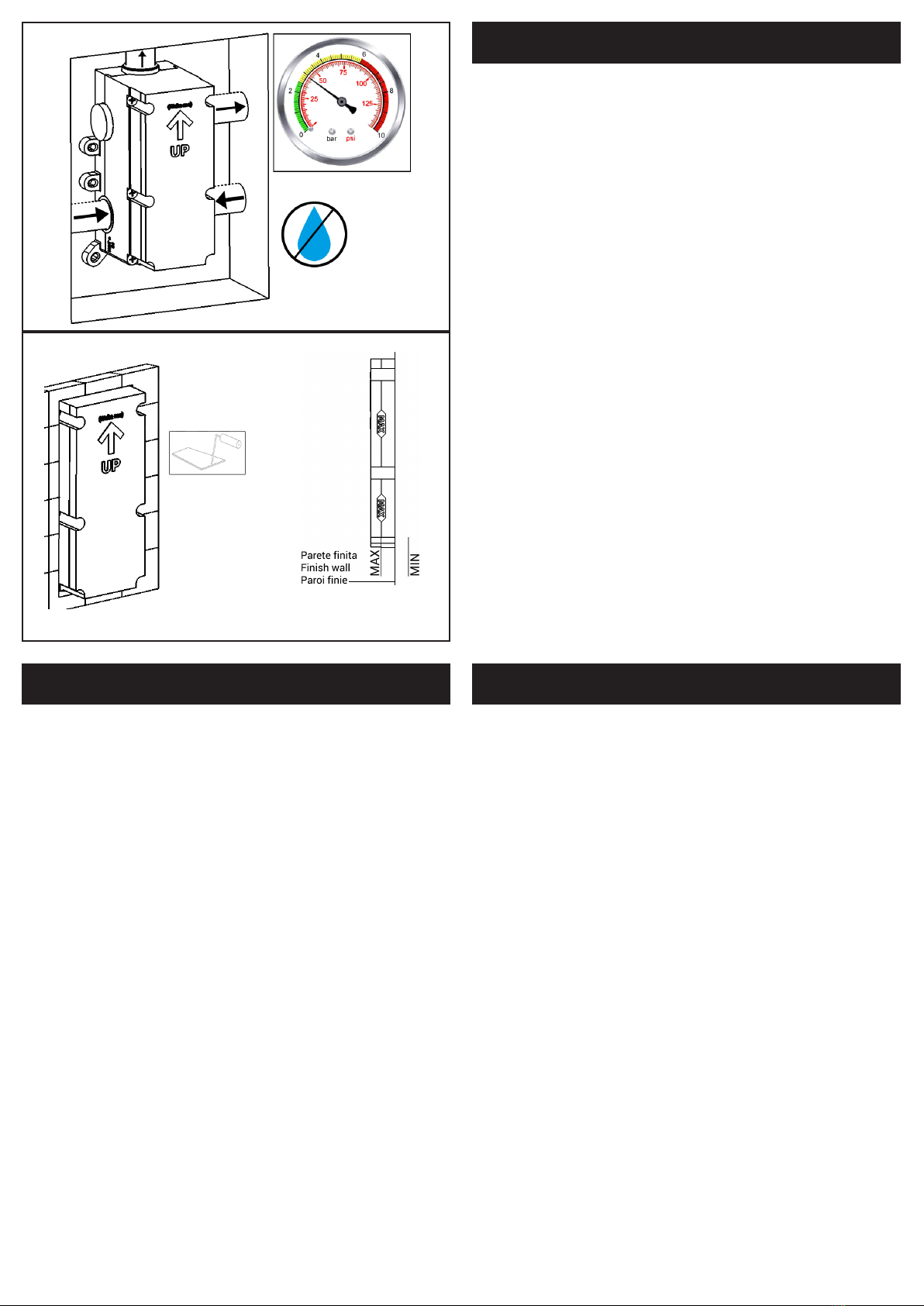
Fig. 1 + Fig. 3: Posizionare il corpo miscelatore nell’alloggiamento realizzato
nella parete, ponendo particolare attenzione ai riferimenti per la posa MIN
e MAX stampati sul carter di protezione. N.B.: i riferimenti MIN e MAX sono
intesi a parete nita, compreso di rivestimento.
Fig. 2: Estrarre i tappi in plastica ed allacciarsi alle tubazioni della rete idrica.
é consigliabile utilizzare canapa o PTFE per garantire la tenuta al letto.
Fig.4: Stabilizzare il corpo all’interno della parete individuando, con l’ausilio
di una livella a bolla, il corretto posizionamento.
Fig. 5: Dopo aver collegato il corpo incasso all’impianto, aprire i rubinetti
d’arresto e vericare la mancanza di perdite nei collegamenti all’impianto.
ATTENZIONE: L’acqua uscirà all’estremità dei tubi collegati alle uscite del
corpo.
Fig. 6: Murare l’incasso diminuendo le dimensioni dell’alloggio no a lo del
carter. Evitare di coprire le viti di bloccaggio scatola.
ATTENZIONE: Vericare a parete nita, compreso di rivestimento, di rientrare
nelle misure minime e massime di incasso indicate sul carter.
L’impermeabilizzazione del muro a discrezione dell’installatore.
N.B.: Per versioni con rosoni di nitura e non piastra, ultimare la parete nita
una volta assemblata la parte esterna.
Completati i lavori richiudere i rubinetti d’arresto non lasciando l’impianto in
pressione.
EN
TECHNICAL DATA
Minimum dynamic pressure: 0.5 bar
Maximum operational pressure: 5 bar
Recommended operational pressure: 1-5 bar
Maximum hot water temperature: 80°
INSTALLATION, MAINTENANCE AND PRELIMINARY CHECKING PROCEDURE
To ensure that the mixer tap unit functions correctly and lasts over time,
the installation and maintenance procedures illustrated in this leaet must
be complied with. Have all work done by a qualied plumber. Ensure that all
debris and dirty have been removed from the system.
It is recommended to use a pressure reducer, if inside the waterpipes there
are static pressure superior 5 bar.
The use of a water softener is recommended.
INSTALLATION
Fig. 1 + Fig. 3: Place the body of the mixer tap unit in the cavity provided
in the wall, taking care to refer to the MIN and MAX installation markings
printed on the protective cover. N.B.: the MIN and MAX markings refer to the
nished wall, complete with tiles.
Fig. 2: Remove the plastic plugs and connect to the system pipes. Hemp o
PTFE should be used to ensure watertight seals on the treads.
Fig.4: Secure the unit inside the wall, using a spirit level to position it correct-
ly.
Fig. 5: After connecting the built-in body to the system, open the stopcocks
and check for leaks in the connections to the system.
WARNING: The water will come out at the end of the tubes connected to the
body outlet.
Fig. 6: Wall the box by reducing the size of the hole to the level of the carter.
Avoid covering the box locking screws.
WARNING: Check with the nished wall, including the coating, to return to
the minimum and maximum installation dimensions indicated on the carter.
N.B.: For versions with rosette and not plate, nish the nished wall once the
external part is assembled.
After completing the works, close the stopcocks. Don’t leave the system
under pressure.
FR
CARATÉRISTIQUES TECHNIQUES
Pression dynamique mini: 0.5 bar
Pression maxi d’exercice: 5 bar
Pression d’exercice recommandée: 1-5 bar
Température maxi eau chaude: 80°
NORMES D’INSTALLATION, D’ENTRETIEN ET VÉRIFICATIONS PRÉLIMINAIRES
Pour que votre appareil fonctionne correctement et dure dans le temps, il est
nécessaire de respecter les modalités d’installation et d’entretien illustrées
dans cet opuscule. Demander l’intervention d’un plombier qualié. Vérier
que l’installation est libre de tous détritus et de toutes impuretés.
Il est recommandé d’utiliser un réducteur de pression en cas de pressions
statiques supérieures à 5 bar.
L’utilisation d’un adoucisseur est également recommandée.
INSTALLATION
Fig. 1 + Fig. 3: Positionner le corps du mélangeur dans le logement pratiqué
dans le mur en tenant compte des références MIN et MAX imprimés sur le
carter de protection. N.B.: les références MIN et MAX tiennent compte du
mur ni, revêtement compris.
Fig. 2: Retirer les bouchons en plastique et effectuer le raccordement aux
conduites du réseau. Il est conseillé d’utiliser du chanvre ou PTFE pour
garantir l’étanchéité des letages.
Fig.4: Stabiliser le corps à l’intérieur du mur en s’aidant d’un niveau à bulle
en vue d’un positionnement correct.
Fig. 5: Après avoir connecté le corps encastrés au système, ouvrez les
robinets d’arrêt et vériez qu’il n’y a pas de fuites dans les connexions du
système.
ATTENTION: L’eau va sortir à la n des tubes connecté à la sortie du corps.
Fig. 6: Murer la boîte en réduisant la taille du logement jusqu’au niveau du
carter. Évitez de couvrir les vis de verrouillage du boîtier.
ATTENTION: Vériez à mur ni, y compris le revêtement, que les dimen-
sions d’installation minimales et maximales indiquées sur le carter soient
respectées.
N.B.: Pour les versions avec rosaces de nition et sans plaque, nissez le
mur ni seulement une fois que la partie externe a été assemblée.
Une fois les travaux terminés, fermez les robinets d’arrêt. Ne laissez pas le
système sous pression.
Fig. 5
Fig. 6
Per versioni con rosoni di nitura e non piastra, ultimare la parete nita una volta assemblata la parte esterna.
For versions with rosette and not plate, nish the nished wall once the external part is assembled.
Pour les versions avec rosaces de nition et sans plaque, nissez le mur ni une fois la partie externe assemblée.


