IT
DATI TECNICI
Pressione dinamica MIN: 0.5 bar
Pressione MAX di esercizio: 5 bar
Pressione di esercizio raccomandata: 1-5 bar
Temperatura MAX acqua calda:80°
NORME DI INSTALLAZIONE, MANUTENZIONE E VERIFICHE PRELIMINARI
Perchè il suo apparecchio funzioni nella maniera corretta e possa durare nel
tempo, occorre che vengano rispettate le modalità di installazione e manu-
tenzione illustrate in questo opuscolo. Adarsi ad un idraulico qualicato.
Assicurarsi che l’impianto sia stato liberato da tutti i detriti e impurità esistenti.
Si raccomanda di utilizzare un riduttore di pressione, se all’interno dell’impian-
to si hanno pressioni statiche superiori a 5 BAR.
Si raccomanda anche l’utilizzo di un addolcitore.
INSTALLAZIONE
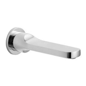
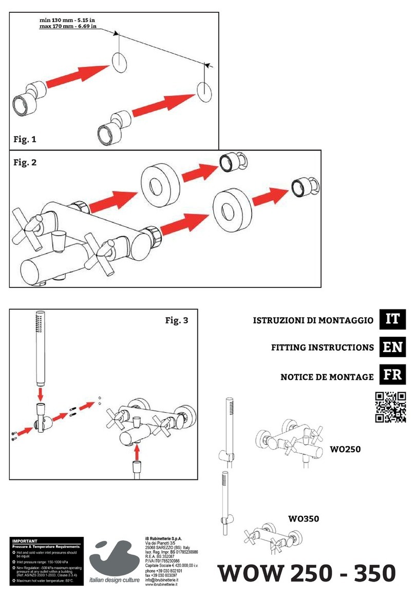
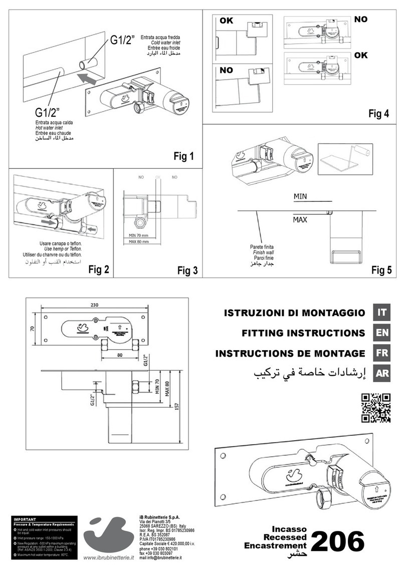
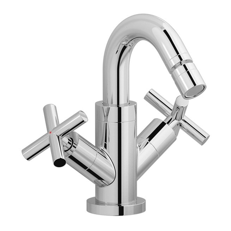
Fig. 1: Praticare un foro sul piano d’appoggio (MIN Ø25 mm – 0.98 in MAX Ø45
- 1.77 in). Inserire il gambo lettato nel foro, posizionando l’OR alla base della
bocca.
Fig. 2: Sotto il piano, inserire la guarnizione e l’anello nel gambo lettato, av-
vitare l’anello lettato, avvitare le viti no al completo bloccaggio. Collegare i
essibili di alimentazione.
Dopo aver collegato il rubinetto all’impianto, aprire i rubinetti d’arresto e ve-
ricare il corretto funzionamento del miscelatore. Controllare la mancanza di
perdite nell’impianto.
PULIZIA
Per una corretta pulizia, lavare esclusivamente con acqua e sapone, risciacqua-
re ed asciugare con una pelle di daino e panno morbido. Evitare assolutamente
l’impiego di alcool, solventi, detersivi solidi o liquidi contenenti sostanze corro-
sive o acide, stronacci con bre sintetiche, spugne abrasive, tamponi con li
metallici, poichè potrebbero alterare irreversibilmente le superci trattate.
L’UTILIZZO DI QUESTO TIPO DI DETERGENTI PER LA PULIZIA DEL RUBINETTO
FA DECADERE QUALSIASI GARANZIA SULLA SUPERFICIE DELLO STESSO DA
PARTE DI IB.
EN
TECHNICAL DATA
Minimum dynamic pressure: 0.5 bar
Maximum operational pressure: 5 bar
Recommended operational pressure: 1-5 bar
Maximum hot water temperature: 80°
INSTALLATION, MAINTENANCE AND PRELIMINARY CHECKING PROCEDURE
To ensure that the mixer tap unit functions correctly and lasts over time, the
installation and maintenance procedures illustrated in this leaet must be
complied with. Have all work done by a qualied plumber. Ensure that all debris
and dirty have been removed from the system.
It is recommended to use a pressure reducer, if inside the waterpipes there are
static pressure superior 5 bar.
The use of a water softener is recommended.
INSTALLATION
Fig. 1: Drill a hole on the support surface (MIN Ø25 mm - 0.98 in MAX Ø45 - 1.77
in). Insert the threaded rod into the hole, positioning the O-ring at the base of
the spout.
Fig. 2: Under the top, insert the gasket and the ring into the threaded rod, screw
the threaded ring, tighten the screws until completely locked. Connect the sup-
ply hoses.
After connecting the body to the system, turn on the stopcocks and check that
the mixer tap unit operates correctly. Keep the tap pressurised for a few minutes
checking eventual leaks.
CLEANING
In order to obtain a correct cleanliness, exclusively wash them with soap and
water, rewash and dry them with a soft towel and deerskin. Avoid the usage of
alcohol, solvents, solid or liquid detergents which contain corrosive or acidic
substances, abrasive sponges, swab with metallic strings because they could
irreversibly compromise the surfaces.
THE USAGE OF THIS KIND OF DETERGNETS DURING THE CLEANING OF THE
MIXER EXCLUDE IB RUBINETTERIE FROM ANY WARRANTY OBLIGATION.
FR
CARATÉRISTIQUES TECHNIQUES
Pression dynamique mini: 0.5 bar
Pression maxi d’exercice: 5 bar
Pression d’exercice recommandée: 1-5 bar
Température maxi eau chaude: 80°
NORMES D’INSTALLATION, D’ENTRETIEN ET VÉRIFICATIONS PRÉLIMINAIRES
Pour que votre appareil fonctionne correctement et dure dans le temps, il est
nécessaire de respecter les modalités d’installation et d’entretien illustrées
dans cet opuscule. Demander l’intervention d’un plombier qualié. Vérier que
l’installation est libre de tous détritus et de toutes impuretés.
Il est recommandé d’utiliser un réducteur de pression en cas de pressions
statiques supérieures à 5 bar.
L’utilisation d’un adoucisseur est également recommandée.
INSTALLATION
Fig.1: Percez un trou sur la surface (MIN Ø25 mm - 0,98 in MAX Ø45 - 1,77 in).
Insérez la tige letée dans le trou, en positionnant le joint à la base du bec.
Fig. 2: De dessous, insérer le joint et la bague dans la tige letée, visser la bague
letée, serrer les vis jusqu’à ce qu’elles soient complétement verrouillées. Con-
nectez les tuyaux d’alimentation.
Après le raccordement du robinet aux tuyauteries, ouvrir le robinet d’arrêt pour
vérier le bon fonctionnement. Vérier l’absence de fuites.
NETTOYAGE
An d’assurer un bon nettoyage, laver exclusivement avec eau et savon, rincer
et essuyer avec un chiffon doux. N’utiliser jamais alcool, solvants, de poudres
à récurer ni de nettoyants acides et éponges abrasives ou éponges métalliques
car risquent de causer des dommages irrémédiables.
L’UTILISE DES CES DETERGENTS POUR LE NETTOYAGE DU MITIGEUR REND
CADUQUE LA GARANTIE SUR LA SURFACE DE-CI PAR IB.
