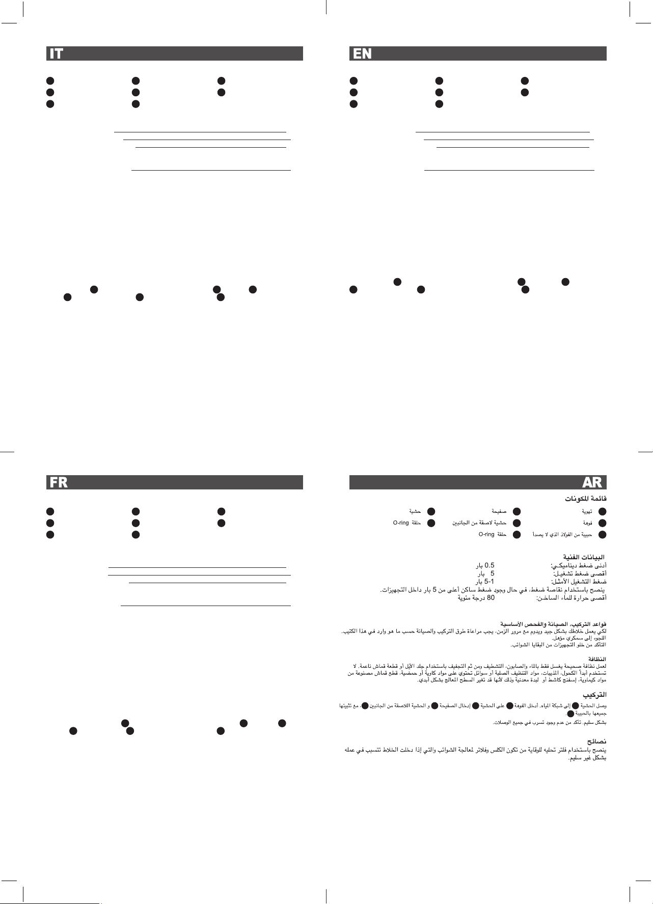
LISTA DEI COMPONENTI
DATI TECNICI
Pressione dinamica minima: 0.5 bar
Pressione di esercizio massima: 5 bar
Pressione di esercizio raccomandata: 1-5 bar
Si raccomanda di utilizzare un riduttore di pressione,
se all’interno dell’impianto si hanno pressioni statiche superiori a 5 bar.
Temperatura massima acqua calda: 80°C
NORME DI INSTALLAZIONE, MANUTENZIONE E VERIFICHE PRELIMINARI
Perché il suo miscelatore funzioni nella maniera corretta e possa durare nel tempo, occorre che vengano
rispettate le modalità di installazione e manutenzione illustrate in questo opuscolo. Affidarsi ad un idraulico
qualificato. Assicurarsi che l’impianto sia liberato da tutti i detriti e impurità esistenti.
PULIZIA
Per una corretta pulizia, lavare esclusivamente con acqua e sapone, risciacquare ed asciugare con una pelle
di daino o panno morbido. Evitare assolutamente l’impiego di alcool, solventi, detersivi solidi o liquidi contenenti
sostanze corrosive o acide, strofinacci prodotti con fibre sintetiche, spugne abrasive e tamponi con fili metallici,
poiché potrebbero alterare irreversibilmente le superfici trattate.
INSTALLAZIONE
Collegare l’inserto
G
alla tubazione della rete idrica. Inserire la bocca
B
sull’inserto
G
, inserendo al
piastra
D
e la guarnizione biadesiva
E
, bloccando il tutto con il grano
C
. Aprire i rubinetti e verificare il
corretto funzionamento della bocca di erogazione, controllare la tenuta di tutti i collegamenti.
CONSIGLI
Si consiglia l’uso di un addolcitore per prevenire la formazione di calcare e di filtri per trattenere le impurità, che
entrandonel miscelatore causerebbero un cattivo funzionamento.
COMPONENTS LIST
TECHNICAL DATA
Minimum dynamic pressure: 0.5 bar
Maximum operational pressure: 5 bar
Recommended operational pressure: 1-5 bar
It is recommended to use a pressure reducer,
if inside the waterpipes there are static pressure superior to 5 bar
Maximumhot water temperature 80°C
INSTALLATION, MAINTENANCE AND PRELIMINARY CHECKING PROCEDURE
To ensure that the mixer tap unit functions correctly and lasts over time, the installation and maintenance pro-
cedures illustrated in this leaflet must be complied with. Have all work done by a qualified plumber. Ensure that
all debris and dirt have been removed from the system.
CLEANING
To clean the unit correctly, use only soap and water, rinse and dry with a chamois leather or soft cloth. Never
use alcohol, solvents, solid or liquid detergents containing corrosive substances or acids, synthetic fibre rags,
abrasive sponges or steel wire scouring pads, since they may cause irreparable damage to the treated surfaces.
INSTALLATION
Connect the insert
G
to the water supply system pipeline. Fit the outlet
B
onto the insert
G
, fitting the plate
D
and the biadhesive seal
E
and securing all parts with the stud bolt
C
.Turn on the taps, check that the
mixer tap functions correctly and check that all the connections are watertight.
USEFUL ADVICE
Users are advised to install a softener to prevent limescale formation and filters to trap dirt, which might cause
malfunctions if they enter the mixer tap.
CARACTÉRISTIQUES TECHNIQUES
Pression dynamique mini.: 0.5 bar
Pression maxi. d’exercice: 5 bar
Pression d’exercice recommandée: 1-5 bar
Il est recommandé d’utiliser un réducteur de pression en cas
de pressions statiques supérieures à 5 bars dans l’installation.
Température maxi. eau chaude: 80°C
NORMES D’INSTALLATION, D’ENTRETIEN ET VÉRIFICATIONS PRÉLIMINAIRES
En vue d’un fonctionnement correct et prolongé de votre mitigeur, respecter les modalités d’installation et
d’entretien illustrées dans cette notice. Demander l’intervention d’un plombier qualifié. Vérifier que l’installation
est libre de tous détritus et de toutes impuretés.
NETTOYAGE
Pour un nettoyage correct, laver exclusivement à l’eau savonneuse, rincer et essuyer avec une peau de cha-
mois ou un chiffon doux. Éviter l’emploi d’alcool, solvants, produits détergents solides ou liquides contenant des
substances corrosives ou acides, les chiffons synthétiques, les éponges abrasives et les pailles de fer, étant
donné qu’ils peuvent endommager irrémédiablement les surfaces traitées.
INSTALLATION
Raccorder la pièce d’adaptation
G
au tuyau du réseau hydrique. Introduire le bras
B
dans l’insert
G
, placer
la plaque
D
et le joint bi-adhésif
E
en bloquant le tout avec le goujon
C
.
Ouvrir les robinets et vérifier si le
mitigeur fonctionne correctement et si tous les raccordements sont étanches.
CONSEILS
Il est conseillé d’installer un adoucisseur d’eau pour éviter toute formation de calcaire ainsi que des filtres
permettant de retenir les impuretés sous peine de dysfonctionnement du mitigeur.
LISTE DES PIÈCES
A
Aeratore
D
Piastra
G
Inserto
B
Bocca
E
Guarnizione biadesiva
H
O-ring
C
Grano inox
F
O-ring
A
Aérateur
D
Plaque
G
Insert
B
Bras
E
Joint bi-adhésif
H
Joint torique
C
Goujon inox
F
Joint torique
A
Aerator
D
Plate
G
Insert
B
Outlet
E
Biadhesive seal
H
O-ring
C
Stainless steel stud bolt
F
O-ring
G D A
H E B
F C
GG BDE
C


