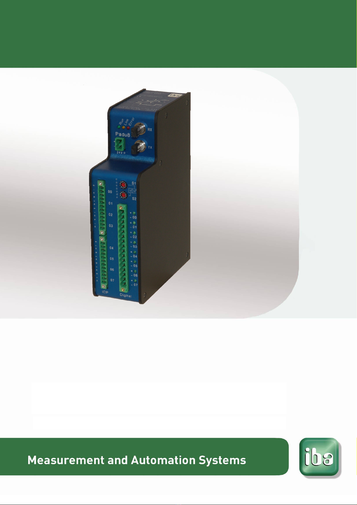
ibaPADU-8-ICP Manual
Issue 1.7 3
Table of contents
1About this manual.............................................................................................5
1.1 Target group...................................................................................................... 5
1.2 Notations........................................................................................................... 5
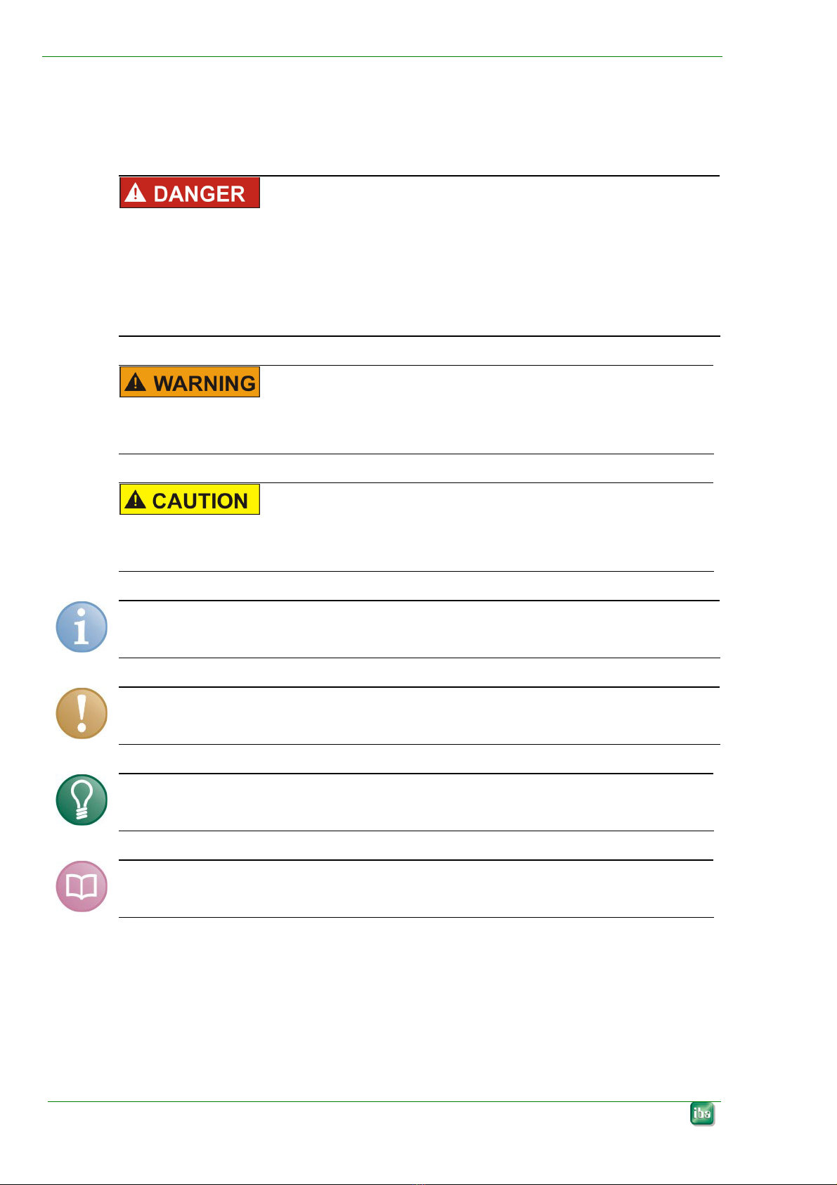
1.3 Used symbols ................................................................................................... 6
2Introduction .......................................................................................................7
3Scope of delivery ..............................................................................................8
4Safety instructions............................................................................................8
4.1 Designated use ................................................................................................. 8
4.2 Special advices ................................................................................................. 8
5System requirements........................................................................................9
5.1 Hardware .......................................................................................................... 9
5.2 Software ............................................................................................................ 9
6Mounting and dismounting ............................................................................10
6.1 Mounting ......................................................................................................... 10
6.2 Dismounting .................................................................................................... 10
7Device description .......................................................................................... 11
7.1 Properties........................................................................................................ 11
7.2 Device view..................................................................................................... 12
7.2.1 Power Supply Connection............................................................................... 13
7.2.2 Fiber-optic Ports RX and TX ........................................................................... 13
7.2.3 Setting the Device Address with S1 and S2 Decade Switches....................... 13
7.2.4 Terminal Blocks Pin Connections X1, X5, X14................................................ 13
7.2.5 Run, Link and Error LED Indicators ................................................................ 14
7.2.6 Binary LED Indicators ..................................................................................... 14
7.2.7 Service Interface ............................................................................................. 15
7.2.8 Shield Connector for Physical Earth ............................................................... 15
8System integration..........................................................................................16
8.1 Process Monitoring Topology Example ........................................................... 17
8.2 Online Machine Condition Monitoring Topology.............................................. 18
9Programmable Settings of the Device...........................................................19
9.1 Sampling Rate ................................................................................................ 19
9.2 Input Gain ....................................................................................................... 19
9.3 Low-Pass Filter ............................................................................................... 20
10 Configuration ..................................................................................................22
10.1 Working with ibaLogic-V3................................................................................ 22
10.1.1 Typical Configuration ...................................................................................... 22