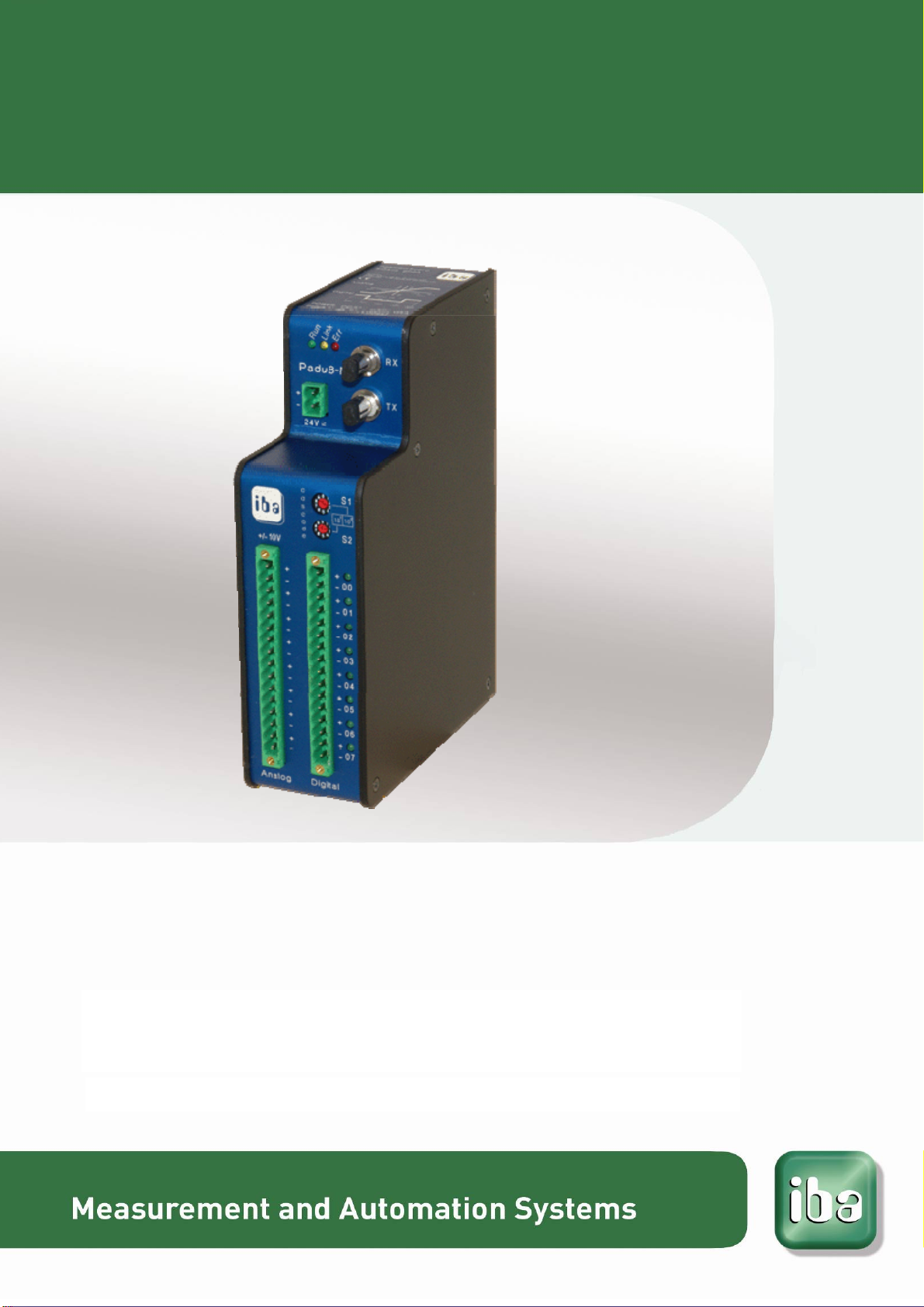
IBA PADU-8-M User manual

Parallel A/D Converter Unit for Fast Measurement
ibaPADU-8-M
Manual
Issue 1.9

2 Issue 1.9
Manufacturer
iba AG
Koenigswarterstr. 44
90762 Fuerth
Germany
Contacts
Main office +49 911 97282-0
Fax +49 911 97282-33
Support +49 911 97282-14
Engineering +49 911 97282-13
E-Mail: [email protected]
Web: www.iba-ag.com
This manual must not be circulated or copied, or its contents utilized and disseminated,
without our express written permission. Any breach or infringement of this provision will
result in liability for damages.
©iba AG 2013, All Rights Reserved
The content of this publication has been checked for compliance with the described
hardware and software. Nevertheless, deviations cannot be excluded completely so
that the full compliance is not guaranteed. However, the information in this publication
is updated regularly. Required corrections are contained in the following regulations or
can be downloaded on the Internet.
The current version is available for download on our web site http://www.iba-ag.com.
Protection note
Windows® is a label and registered trademark of the Microsoft Corporation. Other
product and company names mentioned in this manual can be labels or registered
trademarks of the corresponding owners.
Certification
The device is certified according to the European standards and directives. This device
corresponds to the general safety and health requirements. Further international cus-
tomary standards and directives have been observed.
Issue Date Revision Chapter Author Version HW / FW
V 1.9 09/26/2013 Note on ring topology corrected 8

ibaPADU-8-M Manual
Issue 1.9 3
Table of contents
1About this manual.............................................................................................5
1.1 Target group......................................................................................................5
1.2 Notations...........................................................................................................5
1.3 Used symbols ...................................................................................................6
2Introduction.......................................................................................................7
3Scope of delivery ..............................................................................................7
4Safety instructions............................................................................................8
4.1 Designated use.................................................................................................8
4.2 Special advices.................................................................................................8
5System requirements........................................................................................9
5.1 Hardware ..........................................................................................................9
5.2 Software............................................................................................................9
6Mounting and dismounting............................................................................10
6.1 Mounting .........................................................................................................10
6.2 Dismounting....................................................................................................10
7Device description..........................................................................................11
7.1 Properties........................................................................................................11
7.2 Device view, interfaces and operating elements.............................................12
7.2.1 Power Supply Connection X14 .......................................................................12
7.2.2 Fiber-optic Ports RX (X11) and TX (X10)........................................................12
7.2.3 Setting the Device Address with S1 and S2 Decade Switches.......................12
7.2.4 Terminal Blocks Pin Connections X14, X1, X5................................................13
7.2.5 Run, Link and Error LED Indicators L1…L3....................................................13
7.2.6 Binary LED Indicators L4…L11.......................................................................14
7.2.7 Service Interface (X12) ...................................................................................14
7.2.8 Shield Connector for Physical Earth (X29)......................................................14
8System integration..........................................................................................15
8.1 Process Monitoring Topology Example...........................................................16
8.2 Online Machine Condition Monitoring Topology..............................................17
9Settings of the Device.....................................................................................18
9.1 Sampling Rate ................................................................................................18
9.2 Input Gain .......................................................................................................18
9.3 Low Pass Filter ...............................................................................................18
9.4 Input Impedance .............................................................................................18
10 Data Selection for ibaPADU-8-M ....................................................................19
10.1 Working with ibaLogic-V3................................................................................19

Manual ibaPADU-8-M
4 Issue 1.9
10.1.1 Typical Configuration ......................................................................................19
10.1.2 Hardware Settings ..........................................................................................20
10.1.3 Checking the Communication with the Help of ibaDiag..................................22
10.1.4 Input Resources iba FOB-M/IN.......................................................................24
10.1.5 Output Resources for ibaFOB-M (FOB-M/Out)...............................................25
10.1.6 Control of ibaPADU-8-M in ibaLogic application program...............................26
10.1.7 Data Buffer Size..............................................................................................27
10.2 Configuring with ibaPDA.................................................................................28
10.2.1 Configuring ibaPADU-8-M...............................................................................28
10.2.2 Configuring Triggers........................................................................................32
10.2.3 Configuring the Data Store..............................................................................35
10.2.4 Configuring the Signal View............................................................................36
11 Technical data.................................................................................................37
11.1 Dimensional Drawing......................................................................................38
12 Support and contact.......................................................................................39

ibaPADU-8-M Manual
Issue 1.9 5
1 About this manual
This manual describes the construction, the use and the operation of the device
ibaPADU-8-M.
1.1 Target group
This manual addresses in particular the qualified professionals who are familiar with
handling electrical and electronic modules as well as communication and measurement
technology. A person is regarded to as professional if he/she is capable of assessing
safety and recognizing possible consequences and risks on the basis of his/her spe-
cialist training, knowledge and experience and knowledge of the standard regulations.
1.2 Notations
The following designations are used in this manual:
Action Notations
Menu command Menu „Logic diagram“
Call of menu command „Step 1 – Step 2 – Step 3 – Step x”
Example:
Select menu „Logic diagram – Add – New logic
diagram”
Keys <Key name>
Example: <Alt>; <F1>
Press keys simultaneously <Key name> + <Key name>
Example:
<Alt> + <Ctrl>
Buttons <Button name>
Example:
<OK>; <Cancel>
File names, Paths „File name“, „Path”
Example:
„Test.doc“
Table of contents
Other IBA Media Converter manuals
Popular Media Converter manuals by other brands

H&B
H&B TX-100 Installation and instruction manual

Bolin Technology
Bolin Technology D Series user manual

IFM Electronic
IFM Electronic Efector 400 RN30 Series Device manual

GRASS VALLEY
GRASS VALLEY KUDOSPRO ULC2000 user manual

Linear Technology
Linear Technology DC1523A Demo Manual

Lika
Lika ROTAPULS I28 Series quick start guide

Weidmuller
Weidmuller IE-MC-VL Series Hardware installation guide

Optical Systems Design
Optical Systems Design OSD2139 Series Operator's manual

Tema Telecomunicazioni
Tema Telecomunicazioni AD615/S product manual

KTI Networks
KTI Networks KGC-352 Series installation guide

Gira
Gira 0588 Series operating instructions

Lika
Lika SFA-5000-FD user guide