AS1041TC-CLPage 4
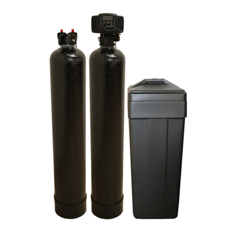
FITTEDWITHMODELWS1VALVE and TCCONTROL
Check the equipmentupon arrivalfordamage orshortagesand reportsametoourOfficeorAgentbefore
starting.
Position the Softenerand Brine Tankon afirmfoundation,preferablyconcrete,withsufficientspacefor
operation and maintenance.The softenermustbe withinOne and aHalfmetresofa240V-10 ampPower
Outlet.The softener MUST be installed undercoverand protected fromthe weatherasthe Valvecontroland
Transformerarenot waterproof.
STEP 1Makesurethe softenertankisemptyand clean.
STEP 2Install the distributortube inthe softenertank,check the heightinrelation totop ofsoftener
tank. (Approximately12mm abovethe top ofthe tank).
STEP 3Placeaplasticcap overthe end of the distributorpipe.Aclean rag orplasticbag will sufficeif
plasticcap isnot available- NO mediamust enterdistributorpipe.
STEP 4Placeawide mouthfunnelinthe mouthofthe tankand load the 41 litresofsoftening resin
and fill withwatertowithin50mm ofthe top.Note:-The resin mustnot be allowed tobe
spilled on the floorasit isvery slippery and dangeroustowalkon.
STEP 5Clean top ofneck and threadsofall tracesofresin.Removethe plasticcap fitted inStep 3
taking carenot toraisethe distributorpipe. NEVER shorten the lengthofthe distributorpipe.
STEP 6Unpack controlvalve,check thattank‘O’ring isinplace. Fitthetop strainer intothe
bottomof thevalve ifnotalreadyfitted.The strainerhasabayonetstyleconnection end.
Assemblethe controlvalvetosoftenertank, and screwdownhand tight.
STEP 7Connectthe Inletand Outletpipesand Drainline tothe controlvalveasperthe instruction
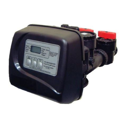
bookinstallation details. Notethedirectional arrowson theValve. Theinletison theright
hand side facing thefrontofthevalve.The drainisfromthe largerelbowon the top of the
valve.The valveInletand Outletthreadsare25mm BSP Femalewitha12mm pushon Hose
connection forthe drainline.
STEP 8Removelidfrombrine tank, connect brine tube fromelbowassemblyon controlvalve, tobrine
risertube inbrine tankensuring tousethe supplied WhiteTube Insert.Then connectbrine
tankoverflowdrainline towastetrap.
.
STEP 9Load Twobagsof25kghigh puritywatersoftenersalt intobrine tankand replacelid.
IBCWaterrecommendsthat onlyhigh puritysalt be used inthe softener.
STEP 10 RefertoInstruction bookletforstartup procedure(placing conditionerintoService")and itis
recommended toread fullythe instruction manualbeforecommencing the installation and
placing the systemintooperation.
Table3
MODEL RESINLITRES BRINETANK -SALT
AST1041TC-CL
41
50
BASICINSTALLATION
OF
IBC TWOTANK WATERSOFTENERSYSTEM

