AST0922-940 Page 10
Introduction
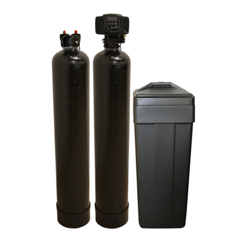
Thankyou forpurchasing awaterconditionersystem
featuring the Series255 withamodel940 Control.
The Model940 Controlprovidesdependabletime
clock based operation. The Series255 valve
combinessimplicitywithreinforced NORYL*
construction toprovide an uncommonlyreliable
appliance. The inherent qualityofthe systemmeans
along lifeofefficient, trouble-free soft water. If
maintenancebecomesnecessary, the Series255/940
Controloffersaunique separation capability
illustrated inthe Servicesection ofthismanual.
Superiordesign
•Singlesynchronouselectricmotor providesall
the powerforthe clock and the operation ofthe
control.
•Electrical wiring isfactory assembled. System
cannot be connected incorrectly.
•Program clock 940 (timer)and 960 Demand
system are interchangeable. Bothunitsprovide
guest regeneration capability.
•System may beindexed manuallywith or
withoutpower toanyone ofitsserviceor
regeneration positions. Legend on timerfaceplate
indicatescontrolvalveposition.
•No moving partsin water stream meansno
closetolerancepartssubject tofouling. Thus, the
systemisespeciallyeffectiveon iron-bearing
water.
•No dynamicseals that couldcauseleakage
through wearorfatigue.
•Control acceptsNORYL*orbrass manifold or
modular bypass valve withoutmodification,
offering completeversatilityand easyplumbing
foranyinstallation.
•Brining control valve builtinto system
eliminatesneed foranybrine valve.
•Drain flow control isbuilt intothe valveto
controlbackwashand fast rinseflowrates.
•NORYLisatrademark ofGEPlastics.
SuperiorOperation
•Directacting system functionsindependentlyof
waterpressure. No pistonsordiaphragmsthat
requireaminimumwaterpressuretooperate.
•Five-cycleoperation providesfordownflow
service, up flowbackwash, downflowbrining,
downflowslowand fast rinse. Asixthposition is
included fortimed refill ofthe brine tank.
•Valve discs are held closed bywater pressure
and therefore, areleaktight. The sealing forces
areincreased asthe waterpressureisincreased.
Valveseatsareinaverticalposition, whichis
design position least vulnerabletoplugging.
•System operation cannotgetoutofphase or
sequence. The controlalwaysreturnstoafixed
serviceposition ofregeneration regardless of
whereinthe regeneration cycleit wasstarted.
•Bypass (unconditioned)water isautomatically
available during regeneration.
Installation
All plumbing and electricalconnectionsmust conform
tolocalcodes. Inspect the unit carefullyforcarrier
shortage orshipping damage.
LocationSelection
•Locateunit asclosetoadrainaspossible
•Ifsupplementary watertreating equipment is
required, makesurethat adequateadditional
spaceisavailable. Locatethe brine tankinan
accessibleplacesothat salt can easilybe added.
•Do not install anyunit closerthan 10ft (3m)of
piping between the outlet ofthe waterconditioner
and the inlet ofthe waterheater. Waterheaters
can transmit heat back downthe coldwaterpipe
intothe controlvalve. Hot watercan severely
damage the controller.
A10ft (3m)totalpipe run (including bends, elbows
etc) isareasonabledistancetoprevent hot water
damage. Apositivewaytoprevent hot waterfrom
flowing fromaheat sourcetothe conditioneristo
install acheck valveinthe soft waterpiping fromthe
conditioner. Ifacheck valveisinstalled, makesure
that the water-heating unit isequipped withaproperly
rated temperatureand pressuresafetyreliefvalve.
Alwaysconformtolocalcodes.
•Do not locatethe unit inan area wherethe temp
everfallsbelow34ºF (1ºC)orover120ºF (49ºC).
•Do not install the unit nearacidoracidfumes.
•Do not exposethe unit topetroleumproducts.
