Judo i-soft@home 5 User manual

Read before use and store!
Installation and operating
instructions
JUDO i-soft@home 5
Fully automatic water softening unit
Valid for: EU countries and Switzerland
Language: English

2 JUDO i-soft@home 5
Inquiries, orders, customer support
JUDO Wasseraufbereitung GmbH
P.O. Box 380
71351 Winnenden
Germany
e-mail: [email protected]
judo.eu
Address
JUDO Wasseraufbereitung GmbH
Hohreuschstraße 39 - 41
71364 Winnenden
Germany
Trademarks:
Trademarks used in this document are protected
and registered trademarks of the respective
holder.
© JUDO Wasseraufbereitung GmbH
71364 Winnenden
Germany
All rights reserved.
Reprints – even of extracts – is only permitted
with special approval.
Dear customer,
Thank you for the confidence you have
shown in us by purchasing this device. In
purchasing this fully automatic water sof-
tening system you have procured a state of
the art device.
This device is suitable for use in cold
drinking water up to a maximum water
and ambient temperature of 30 °C.
Every device has been carefully checked
prior to supply. Nevertheless, if difficul-
ties occur, please contact your responsi-
ble customer service representative (see
back page).
The remote control of the i-
soft@home 5 via mobile phones
and tablets using the connectivity
module (accessories) and the JU
Control App requires a stable in-
ternet connection at the place of
installation of the water softening
unit.
The JU Control App is available for
iOS- and Android.

JUDO i-soft@home 5 3

4 JUDO i-soft@home 5
Contents
1 About these operating instructions. 5
1.1 Symbols used .............................. 5
1.2 Safety instructions and dangers
due to non-observation................ 6
1.3 Units used.................................... 6
2 Intended use ...................................... 6
2.1 Water pressure ............................ 7
2.2 Indication of particular dangers ... 7
3 Product information .......................... 8
3.1 Application ................................... 8
3.2 Materials used ............................. 8
4 Installation ......................................... 9
4.1 General........................................ 9
4.2 Installation of the water softening
system ....................................... 10
4.3 Connection of the water softener
with the salt reservoir................. 13
4.4 Waste water connection and safety
overflow hose ............................ 14
5 Operation ......................................... 15
5.1 General...................................... 15
5.2 Control panel ............................. 15
5.3 Menu functions .......................... 15
5.4 Start of operation ....................... 16
5.5 Menu structure........................... 20
5.6 Function description .................. 21
5.7 Filling with salt ........................... 22
5.8 Leakage alarm........................... 22
5.9 Potential-free signal relay .......... 25
5.10 Integration of the water
softening system in building
control systems.......................... 25
5.11 Connectivity module
(accessory) ................................ 25
5.12 Conversions / changes / spare
parts........................................... 26
5.13 Maintenance/repair.................... 26
5.14 Interruption of operation ............ 26
5.15 Resetting to
factory setting ............................ 26
5.16 Overview of the display
messages .................................. 27
6 Fault.................................................. 28
7 Servicing .......................................... 28
7.1 Cleaning .................................... 28
8 Warranty and maintenance ............ 29
8.1 Inspection by the operator every
two months (visual inspection) .. 29
8.2 Six-monthly maintenance by the
operator ..................................... 29
8.3 Annual maintenance by customer
service ....................................... 29
9 Data sheet ........................................ 30
9.1 Type .......................................... 30
9.2 Technical data ........................... 30
9.3 Installation dimensions .............. 31
9.4 Scope of supply......................... 31
9.5 Accessories ............................... 31
10 Spare parts....................................... 33
11 Disposal ........................................... 34
12 Water hardness conversion table.. 35
13 Customer service ............................ 36

JUDO i-soft@home 5 5
About these operating instructions
1 About these operating in-
structions
These operating instructions must always
be available at the place of use of the water
softening system.
These operating instructions should simplify
getting to know your water softening system
and inform you of its intended applications.
The operating instructions contain important
information pertaining to safe, proper and ef-
ficient operation of the water softening sys-
tem. They contain basic information that
must be observed during installation, opera-
tion and servicing. Observance of this infor-
mation will help to avoid dangers, reduce re-
pair costs and increase the reliability and
service life of the water softening system.
The operating instructions must be read by
each person charged with working on the
water softening system, e.g. for:
–Installation
–Operation
– Servicing
(maintenance, inspection, servicing)
Installation and servicing must only be per-
formed by personnel who have been author-
ised by the manufacturer to do so, i.e. who
are able to fulfil the instructions referred to in
the installation and operating instructions as
well as country-specific regulations.
Alongside the operating instructions and the
legal regulations applicable in the country
and place of use in respect of accident pre-
vention, the recognised technical regula-
tions for safe and professional work must be
observed.
Therefore, these operating instructions must
be read by the installer and the responsible
technical personnel/operators prior to instal-
lation, commissioning and servicing.
Not only must the general safety instruc-
tions listed in chapter “Intended use” be
observed, but also the specific safety in-
structions that are included under the
other main points.
1.1 Symbols used
The safety instructions contained in these
operating instructions are labelled with the
following symbols:
Instructions attached directly to the rotary
flange fitting or the water softening system,
such as:
– Direction of flow
– Type label
– Cleaning information
must be observed without fail and main-
tained so that they are always legible.
NOTICE
Indication of
existing dan-
gers
Warning of electric voltage
Torques specified by the manu-
facturer
User tips and other information
Fig. 1: Rotary flange fitting

6 JUDO i-soft@home 5
Intended use
1.2 Safety instructions and dan-
gers due to non-observation
In particular, non-observation of the general
danger symbols is associated with the fol-
lowing typical hazards:
– Failure of important water softening sys-
tem functions.
– Endangering of persons due to electrical
and mechanical effects.
– Endangering of persons and the envi-
ronment due to leaks.
Any working methods that might endanger
safety must be avoided.
Non-observation of these operating instruc-
tions and the safety instructions herein may
endanger persons, as well as the environ-
ment and the device itself.
1.3 Units used
The following units which do not form part of
the SI (Système International d’Unités) sys-
tem are used:
2 Intended use
Both installation and use of the water soften-
ing system are subject to the applicable na-
tional regulations.
Alongside the operating instructions, the le-
gal regulations applicable in the country and
place of use in respect of accident preven-
tion, the recognised technical regulations for
safe and professional work must be ob-
served.
The water to be softened must comply
with the European Drinking Water Direc-
tive!
The manufacturer/supplier must be consult-
ed before using water of a different quality or
water with additional additives!
The water softening system is suitable for
use in cold drinking water up to a maximum
ambient temperature of 30 °C.
It is manufactured according to the state of
the art and recognised German safety regu-
lations.
The water softening system may only be
used as described in the operating instruc-
tions. Any other use or use beyond the spec-
ified use is considered to represent incorrect
use.
Additional dangers exist in the event of incor-
rect use and in the event of non-observation
of the danger symbols and safety instructions.
The manufacturer/supplier shall not be re-
sponsible for any resulting damage. All risks
are borne solely by the user.
Intended use includes observance of the op-
erating instructions.
The manufacturer/supplier must be consult-
ed before using the water softening system
outside the limits of use described in these
operating instructions.
Quan-
tity Unit Conversion
Nomi-
nal di-
ameter
1" corresponds to DN 25
Pres-
sure
bar 1 bar = 100000 Pa
= 0.1 N/mm²
≈14.5 psi
Water
hard-
ness1)
1) For conversion of water hardness
units see chapter 12 “Water hard-
ness conversion table”.
°dH 1 ˚dH = 0.1783 mmol/l
Alkaline earth ions
(hardness
producing ions)
= 17.8 ppm CaCO3

JUDO i-soft@home 5 7
Intended use
The water softening system must only be
used as intended in a technically fault-free
state, while maintaining safety and hazard
awareness, and in compliance with the op-
erating instructions.
Ensure that malfunctions are rectified
immediately!
So that the waste water can be safely
drained away both during operation and also
in the event of a possible system defect, the
specifications given in chapter 4.1.1 “Requi-
rements for the place of installation” must be
closely observed!
NOTICE
(see chapter 1.2 “Safety instructions and
dangers due to non-observation”)
The spent regenerating salt is removed from
the water softening columns together with
waste water. Therefore it must not be used
for irrigation or similar purposes.
The designed capacity of the water softening
system is such that it is capable of partially
softening the entire water requirement for a
single or multiple family dwelling as well as
corresponding partial water quantities for hot
water, swimming pool, washing machine and
dishwasher.
2.1 Water pressure
The water pressure must be between 2 bar
and 7 bar.
The water pressure must not fall below 2 bar
as otherwise the function can be impaired! If
the water softening system is not regularly
serviced, the softening function can be im-
paired.
NOTICE
(see chapter 1.2 “Safety instructions and
dangers due to non-observation”)
Where the water pressure is greater than
7bar, a pressure reducer must be installed
upstream of the water softening system
(see fig. 2)
. If the operating pressure is great-
er than 7 bar, malfunctions can occur.
The optimum operating pressure for the wa-
ter softening system is between 3 bar and
5 bar. This is where it operates most eco-
nomically.
2.2 Indication of particular dan-
gers
2.2.1 Electrical devices/installations
Electrical devices/installations that are not
splash-proof and are located in the vicinity of
the water softening system may be dam-
aged by water that escapes during installa-
tion or in the event of incorrect use of the wa-
ter softening system. If the electrical
devices/installations are connected to the
power supply, it is also possible that a short-
circuit could occur. Should this occur there is
a risk of electric shocks to people. Therefore
electrical devices/furnishings and equip-
ment in the vicinity must be splashproof and/
or comply with the legal regulations for wet
areas.
Fig. 2: Pressure reducer upstream of the system
We recommend installation of a
pressure reducer for water pres-
sures between 5 and 7 bar.
No electrical cables and equipment
may be located below or in the im-
mediate vicinity of the water soften-
ing system!
1 = Pressure reducer
1

8 JUDO i-soft@home 5
Product information
NOTICE
(see chapter 1.2 “Safety instructions and
dangers due to non-observation”)
Caution when touching without the cover!
During operation, electronic components
can become hot. Also there is a danger due
to moving parts.
Potential-free output
Switching voltage............. maximum 24 V
Current ................................ maximum 1 A
(see chapter 5.9 “Potential-free signal re-
lay”)
3 Product information
3.1 Application
The water softening system is suitable for use
with cold drinking water having a maximum
water temperature of up to 30 °C.
NOTICE
(see chapter 1.2 “Safety instructions and
dangers due to non-observation”)
Usage limitations see chapter 2 “Intended
use”.
This water softening system is for protection
of water pipes and the water heater against
limescale deposits.
With partially softened water, devices and fit-
tings are preserved and the consumption of
washing and cleaning agents reduced.
3.2 Materials used
The materials used are resistant to the phys-
ical, chemical and corrosive loads expected
to be encountered in drinking water and fulfil
the specifications required by DIN
EN 14743 and DIN 19636-100 (“Water sof-
tening systems (cation exchangers) in drink-
ing water installations”). All materials are hy-
gienically and physiologically harmless.
Plastics fulfil the KTW Guideline (Guideline
for the Hygienic Assessment of Organic Ma-
terials in Contact with Drinking Water) of the
German Federal Environmental Agency
(UBA). Metallic materials fulfil the require-
ments of DIN 50930-6 (Effect of metallic ma-
terials on the quality of drinking water).
In the power supply unit the mains
voltage is reduced to a safe low volt-
age of 24 V which is then used to op-
erate the system electronics. No oth-
er power supply units must be used.
Only low voltages can be used for
the remote transmission of the fault
indication via the potential-free out-
put!
Limescale deposits block the water
supply and therefore can result in in-
creased energy consumption.

JUDO i-soft@home 5 9
Installation
4Installation
4.1 General
Installation must only be performed by suit-
ably qualified technical personnel.
The chapter 2 “Intended use” must be ob-
served without fail!
The pipe must be able to safely support the
water softening system.
Otherwise mechanical damage to the pipe
up to and including breakage can result.
This can result in severe water damage.
Should such an event occur, persons in the
vicinity of the water softening system are ex-
posed to a risk of injury of harm because of
the large water volumes that could escape.
The supplied support elements are used for
additional support and fixing of the pipe (see
chapter 4.2.3 “Installation of the support ele-
ments”).
The spatial requirements of the system can
be found in chapter 9.3 “Installation dimen-
sions”.
At least 300 mm clearance is required
above the water softening system, so that all
maintenance work can be properly per-
formed.
4.1.1 Requirements for the place of
installation
– The ambient temperature must not ex-
ceed 30 °C!
– So that it is possible to safely drain the
waste water (regeneration) during oper-
ation and also in the event that a system
defect occurs, the specifications given in
chapter 4 “Installation” must be precisely
followed!
If the waste water cannot be safely and
completely drained, it is possible that
property damage to the home and fur-
nishings may be caused by the water.
– A shut-off valve must be installed up-
stream and downstream of the water
softening system! This allows the water
supply to be disconnected for water sof-
tening system maintenance, repairs or in
case of malfunction. Likewise flooding
and severe water damage to household
furnishings and equipment can be avoid-
ed in this way.
– The installation room must be dry and
free from frost. Unauthorised persons
must not be able to access the water sof-
tening system.
– The water softening system must not be
subject to severe impacts.
– The device can be installed in all com-
mercially available drinking water pipes.
– Installation of the water softening system
upstream of the water meter is forbid-
den!
– Installation downstream of the protective
filter as per DIN EN 13443-1 and DIN
19628.
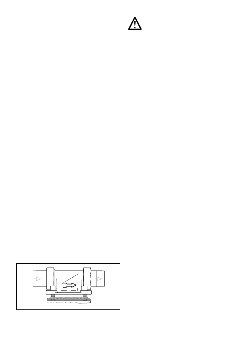
4.1.2 Mounting orientation
4.1.3 Power supply
The mains voltage must not be interrupt-
ed (e.g. via a light switch).
To ensure fault-free operation, ob-
serve the following requirements:
A permanent power connection (230
V, 50 Hz) must be available.
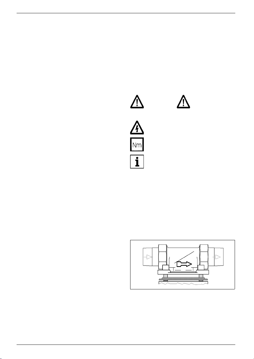
Always install the water softening
system in an upright position
(± 5°)! If this is not observed, in-
correct functioning may result.
A splash-proof socket, complying
with the legal regulations for wet are-
as, is required for the power supply
unit.

10 JUDO i-soft@home 5
Installation
If the water softening system does not have
a permanent power connection,
– Regeneration will not take place,
– No fault warnings will be output.
– Water leakage or even water damage
may occur during a regeneration as a re-
sult of a loss of power.
4.2 Installation of the water sof-
tening system
The two individual softeners are connected
to the pipe via the parallel connection flange
(JQT) The spatial requirements of the sys-
tem can be found in chapter 9.3 “Installation
dimensions”.
4.2.1 Installation of the rotary flange
fitting (JQE)
The rotary flange fitting serves as a connect-
ing piece between the pipe and the water
softening system.
It is suitable both for horizontal and vertical
pipes.
The installation height depends on the pipe
course. If the salt reservoirs are placed near
the water softening system, the minimum in-
stallation height of the water softening sys-
tem from the floor to the rotary flange fitting
is 55 cm.
The rotary flange fitting must be installed
in the direction of flow. This is indicated
by an arrow integral with the casting (see
fig. 3).
The flange surface of the rotary flange fitting
must be upright! The rotary flange fitting
must be fitted so that it is free from mechan-
ical stress or strain. Otherwise mechanical
damage of the rotary flange fitting may re-
sult. This can result in severe water dam-
age.
Therefore when installing, ensure that no
large forces act on the pipe, rotary flange fit-
ting or water softening system.
4.2.2 Installation of the bypass
valve (JQX)
If a bypass valve is used between the rotary
flange fitting and the water softening unit it
will remain possible to continue to draw a
supply of untreated drinking water during
possible maintenance on the system.
– First flush the pipe with the newly in-
stalled rotary flange fitting JQE. The ro-
tary flange fitting is still sealed by the
black mounting cover.
– Then shut-off the water again (at the
stopcock or shut-off valve) and remove
the mounting cover of the rotary flange
fitting.
– Connect the bypass valve with the rotary
flange fitting, by engaging the bayonet,
on the flange side with the cast-in letter
“R” (R=Rohr [pipe]) (see fig. 4).
Fig. 3: Rotary flange fitting
If this requirement is ignored, the
water softening unit will not work.

JUDO i-soft@home 5 11
Installation
The profile of the profile flange seal must
point towards the rotary flange fitting (see
fig. 5). If this is not observed, the sealing
may not be perfect resulting in water escap-
ing. This could result in water damage to the
home and furnishings and equipment.
– Fully tighten the four M6×25 hexagon
socket head screws.
The hand wheel of the bypass valve can ei-
ther project vertically upwards or to the side.
Installation should be performed so that, de-
pendent on the local circumstances, the
hand wheel can be easily accessed.
4.2.3 Installation of the support ele-
ments
The bracket set (2 brackets with one pipe
clamp each) is screwed to the wall with 4
hexagon head screws.
Notes on installing the wall support (contain-
er support) are included in the correspond-
ing installation instructions.
Fig. 4: Bypass valve (JQX)
Fig. 5: Profile flange seal
Rotary flange fitting
Handwheel
Device-side flange (“G”)
Pipe-sideflange
(“R”)
Select the tightening torque (about 4
Nm) so that the seal works effective-
ly!
Fig. 6: Support elements
Parallel
connection flange
Bracket
set
Rotary flange
fitting
Wall support
Bypass
valve

12 JUDO i-soft@home 5
Installation
4.2.4 Installation of the parallel con-
nection flange (JQT)
– Check whether the profile of the profile
flange seal is pointing toward the bypass
valve (see fig. 7).
– Connect the flange of the parallel con-
nection flange (JQT) to the bypass valve
(JQX) by latching in the bayonet connec-
tion and then tighten the four hexagon
socket head screws.
4.2.5 Installation of the two individ-
ual softeners
The connection flange of the water softening
unit is covered by a white protective cap.
This protective cap is secured using four
hexagon socket head screws M6×130.
– Loosen all four hexagon socket head
screws M6×130, but do not screw out
completely (bayonet connection)!
– Remove the white protective cap.
The profile of the profile flange seal must
point towards the parallel connection flange.
If this is not observed, water leaks may oc-
cur. This can result in water damage to the
building, furnishings and equipment.
– Raise the water softening unit and swivel
approximately 30° in an anti-clockwise
direction.
– Position the water softening unit on the
parallel connection flange so that the
screw heads project through the bayonet
holes (see fig. 8 I).
– Swivel the water softening unit back ap-
proximately 30° in a clockwise direction.
– Fully tighten the four M6×130 hexagon
socket head screws (see fig. 8 II).
After installation of the water softening units,
push out the wall support until it touches the
cladding of the devices and the devices
hang vertically on the wall. Then tighten the
screws of the wall support.
Fig. 7: Profile flange seal
Select the tightening torque (about
4 Nm) so that the seal is effective
and the water softening system is
not damaged or strained!
Fig. 8: Bayonet function (fig. similar)
I
II

JUDO i-soft@home 5 13
Installation
4.3 Connection of the water softener with the salt reservoir
Procedure (see fig. 9):
1. Push the lance up to the stop in the salt
reservoir.
2. To lock, turn the lance through 90° in the
clockwise direction (up to the stop).
The salt reservoir can be placed below the
water softener or next to it on the floor.
Fig. 9: Connection of the water softening system with the salt reservoir
1.
2.
Marking arrow
unlocked
Marking arrow
locked
Lance
Salt reser-
voir
Note the marking arrow:
In doing so the arrow must point to
the side (see fig. 9)!
Note the marking arrow:
The arrow must now point to the
front side of the salt reservoir (see
fig. 9)!

14 JUDO i-soft@home 5
Installation
4.4 Waste water connection and safety overflow hose
The hoses for the regeneration waste water
and the safety overflow must both be routed
without any kinks and with a steady down-
ward slope to the water trap (in the scope of
supply). The water trap ensures a free dis-
charge in accordance with DIN EN 1717
(see fig. 10).
The waste water hose with 11 mm outside
diameter must not be routed any higher than
the control head. The hose length must not
exceed 3 m.
The safety overflow hose with 19 mm out-
side diameter must be routed with a steady
downward slope to the water trap.
If a steady downward slope to the water trap
cannot be achieved at the location of instal-
lation, then a saltwater-resistant pumping
system must be installed to convey the re-
generation waste water.
Fig. 10: Connection to the water trap
Waste water hoses
(with steady
downward slope!)
Safety overflow hoses
(with steady
downward slope!)

JUDO i-soft@home 5 15
Operation
5 Operation
5.1 General
Operation start, setting the raw water
hardness, the mixing and the filling with
salt must be performed separately for
each individual softener.
5.2 Control panel
Operation of the water softening system
takes place via the keypad and display (see
fig. 11).
Key functions:
Display background lighting:
– none: normal operation
– alternating light blue/dark blue:
With a water flow
– white: when pressing a key
– yellow: for warning messages
– red: for fault indications
5.3 Menu functions
Pressing the key calls the main menu:
The next or previous sub-menu is displayed
using keys and and called using the
OK key.
In the sub-menu individual values are in-
creased or decreased using keys and
and then accepted using the OK key.
Sub-menus:
Regeneration
– manual regeneration start (see
chapter 5.4.2 “Manually starting regen-
eration of the water softening system”)
Leakage alarm
(Only visible, if the leakage alarm is activat-
ed. For activation, see chapter 5.8.1.)
– Start sleep mode
Fig. 11: Water softening system control panel
Access to the main menu (see
chapter 5.3 “Menu functions”)
- Scroll up in the menu
- Increase value
- Scroll down in the menu
- Reduce value
One menu level back
without saving
Direct access to the information
menu (see section „• Info“
in chapter 5.3)
Two line display
Keypad
Direct access to the settings
of the residual hardness (see
chapter 5.4.3 “Setting the desired
water hardness”)
- Access to the sub-menu
- Accept value and save
and one menu level back
- Acknowledge message
Main menu
• Regeneration

16 JUDO i-soft@home 5
Operation
Settings
– Language:
DE, EN, FR, NL, IT
– Desired water hardness (see
chapter 5.4.3 “Setting the desired water
hardness”)
– Correction of the desired water hardness
(see chapter 5.4.5 “Desired water hard-
ness recalibration”)
– Salt top-up quantity, salt reserve
– Leakage alarm on/off (limit values and
sleep mode time only visible if leakage
alarm is activated).
– Water hardness unit:
°dH, °e, °f, gpg, ppm, mmol/l, mval/l
– Lighting, contrast, tone
– Functioning of the fault indication relay
(see chapter 5.9 “Potential-free signal
relay”)
– Factory setting
(see chapter 5.15 “Resetting to factory
setting”)
Operating data
– Total raw water volume since commis-
sioning [m³]
– Total number of regenerations since
commissioning
– Total number of maintenances since
commissioning
Info
Various information is displayed here such
as salt reserves and capacity, device type,
device number, customer service telephone
number, history of the warning messages
and fault indications, software version, hard-
ware version, the date for the next neces-
sary maintenance intervention and the cur-
rent (instantaneous) water flow.
5.4 Start of operation
– To shorten commissioning, fill approxi-
mately 5 litres of water into the salt res-
ervoir (until just above the intermediate
bottom).
– Fill 25 - 50 kg of regenerating salt into
the salt reservoir.
The regenerating salt must as a minimum
comply with the requirements of DIN EN 973
and be of food-grade.
Our recommendation: Broxo or Solvay
salt, either as blocks, tablets or coarse
grains 7 - 15 mm. If other regenerating salts
are used, then the salt reservoir must be
cleaned at shorter intervals and the intake
strainer replaced more frequently.
– Remove the cover.
– Enter the date of installation on the label
(see fig. 12).
– Open the water supply (stopcock or
shut-off valve).
– Ensure that the bypass valve (if in-
stalled) is set to “Operate”.
NOTICE
For safety reasons, the water softening sys-
tem must be immediately flushed and re-
generated for bleeding:
See chapters 5.4.1 and 5.4.2 for this pur-
pose!
Fig. 12: Device and order no. plus
Label “Date of installation”
Device-no.
Order no.
Label
“Date of installation”

JUDO i-soft@home 5 17
Operation
5.4.1 Flushing the water softening
system
– To do so open a tap (as close as possi-
ble to the water softening system).
– After a minute’s flushing (both resin con-
tainers are vented), plug the power sup-
ply unit into the socket.
After connection to the power supply, the
electronics automatically perform a self-test
and preconfigure the regulation system.
Status display:
After a successful conclusion, the following
text is output to the display:
The desired water hardness is pre-set to
8°dH.
Information about setting the desired water
hardness is available in chapter 5.4.3 “Set-
ting the desired water hardness”.
5.4.2 Manually starting regeneration
of the water softening system
To do so, the water softening system must
be in an operating position. The status is
shown on the display (see fig. 13).
Press key . The display shows the fol-
lowing:
Press the <OK> key. The display shows the
following:
Pressing <OK> starts regeneration.
Then “Regeneration” is output to the display.
Regeneration is completed after about
20 minutes. The display shows the status
again (see fig. 13).
5.4.3 Setting the desired water
hardness
The water softening system is pre-set to a
desired water hardness of 8 °dH Another
desired water hardness is set as follows:
Press key . The display shows the fol-
lowing:
Use the key to reduce the desired water
hardness set and the key to increase it.
The step size is 1 °dH.
The desired water hardness value chosen is
saved by pressing <OK>.
The desired water hardness is automatically
set during operation. For this to happen, ap-
prox. 10 l of water must flow through the wa-
ter softening system (at a rate of approx.
500 l/h).
An optional hardness measuring instrument
(see chapter 9.5 “Accessories”) can be used
to check the desired water hardness.
The sample water for checking the water
hardness can be drawn at the bypass valve
or from a water tap connection downstream
of the water softening system.
It must be ensured that the reset mixing wa-
ter quantity has flown from the water soften-
ing system to the drawing point. For a cor-
rect measuring value comparison, the
samples should be taken with a normal wa-
ter flow (one tap fully open). During drawing,
no large volume of water should be drawn at
another point.
Fig. 13: Status display
Operation
Res. hard. 8 °dH
Main menu
• Regeneration
Regeneration
start
Res. hard.
8 °dH

18 JUDO i-soft@home 5
Operation
5.4.4 Desired water hardness set-
ting limitations
The water softening system control unit
checks if the desired water hardness is cor-
rectly set.
1. Limitation due to the mixing valve
setting range:
The desired water hardness can be set be-
tween 1 °dH and half the value of the un-
treated drinking water hardness +2 °dH.
Example: Untreated drinking water hard-
ness = 18 °dH
Desired water hardness setting:
1 to 11 °dH
The desired water hardness cannot be set to
a higher value.
The maximum hardness that can be set via
the menu with the key is limited to the val-
ue calculated by the control unit. Higher val-
ues are not possible.
2. Limitation due to the maximum value
for sodium in the drinking water:
After the softening, the sodium concentra-
tion in the mixing water increases, depend-
ent on the raw water hardness and the set
desired water hardness.
According to current national drinking water
legislation, the limit value for sodium in
drinking water is 200 mg/l. Mineral and table
water are not affected by this. Their limit val-
ues are much higher, partially greater than
1000 mg sodium per litre.
If the calculated total sodium content ex-
ceeds the valve permitted by the drinking
water legislation of 200 mg/l, then it can be
corrected by increasing the desired water
hardness.
Based on the raw water hardness and de-
sired water hardness, the electronics deter-
mine the sodium content. The electronics do
not take into account the sodium content of
the raw water. If the limit value of the drink-
ing water ordinance is exceeded, the follow-
ing messages appear on the display:
Calculation of the sodium content
°dH Raw water hardness (ask
the water supply company
or measure with hardness
measuring instrument)
- °dH Residual hardness (meas-
ured value)
= °dH Difference in water hardness
×8.2 mg Na+/l × °dH
Na ions exchange value
= mg/l Increase of the sodium con-
tent by softening
+ mg/l sodium already present in
the raw water (ask the water
supply company)
= mg/l Total sodium content in the
mixing water
Example calculation of the sodium con-
tent
20 °dH Raw water hardness
- 8 °dH Residual hardness
= 12 °dH Difference in water hardness
×8.2
= 98 mg/l Due to softening:
+ 10 mg/l From water supply company
= 108 mg/l In total
Attention!
Sodium limit val

JUDO i-soft@home 5 19
Operation
and after 3 seconds:
After 3 seconds the permissible minimum
value of the desired water hardness is dis-
played. This may be followed by the mes-
sage:
The following is shown after 3 seconds:
After pressing the <OK> key the desired wa-
ter hardness minimum value is memorized
as the new setpoint value. By pressing the
keys and , the desired water hardness
can be set and forced with the <OK> key
even if the sodium value is exceeded.
5.4.5 Desired water hardness
recalibration
Due to the different composition of the de-
sired water, the desired water hardness may
not be reached. In this case, the desired wa-
ter hardness can be adapted to the water
quality.
If, for example, the water hardness is set at
6 °dH, but the residual hardness measured
is 8 °dH, the water hardness can be adapted
as follows:
Press the key 1x and then 2x. The
display shows the following:
Press key <OK> 1x and then key as often
as necessary, until the display indicates the
following:
Press the <OK> key. The display shows the
following:
Use the key to reduce the measured re-
sidual hardness value and the key to in-
crease it. The step size is 1 °dH.
The chosen residual hardness setting is
saved by pressing <OK>.
On the basis of these values the control unit
generates the necessary correction value.
The recalibration of the residual hardness is
reset as soon as the customer settings are
reset to the factory settings (see
chapter 5.15 “Resetting to factory setting”).
If the sodium content is exceeded, a
“2” is displayed at the end of the first
line of the display.
see instruction
manual
min. permissible
Res. hard. 10 °dH
Accept <OK>
or setting
The recalibration of the residual
hardness is displayed by a small “1”
at the end of the first line.
Main menu
• Settings
Setting
• Res. hard. corr.
Actual hardness
8 °dH

20 JUDO i-soft@home 5
Operation
5.5 Menu structure
Fig. 14: Menu structure
This manual suits for next models
1
Table of contents
Other Judo Water Dispenser manuals

Judo
Judo i-soft@home User manual

Judo
Judo QUICKSOFT-P User manual

Judo
Judo PROFI-PLUS Series User manual

Judo
Judo QUICKSOFT MEGA User manual

Judo
Judo i-soft TGA 4 User manual

Judo
Judo JUDOMAT JM 4 WZ-P User manual

Judo
Judo i-soft User manual

Judo
Judo QUICKSOFT-DUO User manual

Judo
Judo QUICKSOFT-UNO User manual

Judo
Judo PROMI User manual