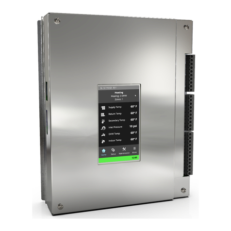
IBC P-242 User manual

120-199-R3 |5/16/2018 www.ibcboiler.com │1
P-242 Installing a V-10 touchscreen controller
IBC Part # Description Boiler Model
P-242 V-10 touchscreen controller installment kit All SL models
VFC Series: VFC 15-150,
VFC 45-225
Danger
Installing and servicing boiler equipment, parts and accessories can be hazardous due to gas and electrical
components. Only trained personnel should install or service heating equipment. When working on boiler
equipment, observe precautions in the literature, on tags, and on labels attached to the unit.
For your safety, turn off electrical power supply at service panel and allow unit to cool before proceeding. Failure
to do so can cause severe personal injury or death. The ability to properly perform service on this equipment
requires certain expertise, mechanical skills, tools, and equipment. If you do not possess these, do not attempt
to perform any service on this equipment. Failure to follow this warning could result in possible damage to this
equipment, serious personal injury, or death.
Kit contents
1 x Touchscreen boiler controller - 500-044
1 x Control Cover - 250-591
1 x Wiring Diagram Label - 080-123
1 x Touchscreen manual - 120-198
Replacing a controller with the V-10 touchscreen controller requires the following:
1. Removing the old controller.
2. Installing the new touchscreen controller.
3. Wiring the touchscreen controller.
4. Programming and testing connections.
Installation Instructions

In addition to the following instructions, refer to the
boiler's current Installation and Operating Instructions
manual as well as the V-10 Touchscreen Controller
manual.
Note
The touchscreen controller has new features
including electrical connections that differ from
the 5 button controller (see the Electrical
Ladder diagram on the back page).
1. Record all settings from the original boiler
controller before beginning the replacement. For
example, record settings in the Installer Setup
menu, Multi-boiler menu, and Load Pairing.
2. Turn off the power to the boiler.
3. Remove the boiler’s main door.
4. Remove the controller’s right side electrical
terminal block cover.
5. From the right side of the IBC board, unplug the
orange and green terminal block connectors.
6. Remove the controller’s front cover.
7. Remove the four Phillips screws securing the
back plate of the IBC controller to the boiler
cabinet (see figure 1).
Figure 1 Removing the old controller
2│www.ibcboiler.com
8. Hold the board in place as you unplug the
connectors from the rear of the board.
9. Remove the controller board from the boiler.
Removing the touchscreen
controller
1. Turn off the power to the boiler.
2. Remove the boiler’s main door.
3. Remove the controller’s right side electrical
terminal block cover.
4. Unplug the P/V terminal strip and the two low
voltage terminal strips. If connected, also
unplug the Alarm terminal.
5. Swing out the controller to access the back
side connections.
6. Unplug all the connectors from the rear of the
board.
7. Lift up on the bottom-left corner of the controller
and pull forward, removing the controller from
the boiler.
Installing the new
touchscreen controller
Caution
Since static electricity can damage the
electronic components on the boiler controller
avoid touching the electronics.
If the boiler has a controller mounted on a swing-out
door, you will need to swap the controller's mounting
plate with the one attached to the controller being
replaced.

Swapping the controller's mounting
plate (if required)
1. Remove the front cover from the control board (4
Phillips screws).
2. Remove the five Phillips screws (see Figure 2).
You will need to do this for both boards, starting
with the old controller first.
Figure 2 Swing-out mounting plate
3. Carefully lift the controls off the mounting plates.
4. Place the screen control onto the swing out door
style control mounting plate, and reinstall the 5
screws. The screws should not be over tightened.
120-199-R3 |5/16/2018 www.ibcboiler.com 3
5. For swing-out style controllers:
a. Install the controller by inserting the swing-
out back-plate pivot tabs into the
corresponding holes in the controller's
connections box, upper tab first.
b. Plug the four connectors into the back of the
board.
6. For older IBC boiler models:
a. Remove the front cover from the new
controller.
b. Support the board as you plug the four
connectors into the back of the board.
c. Screw the back-plate of the controller to the
cabinet of the boiler using the four Phillips
screws previously removed with the old
controller.
d. Replace the new front cover of the
controller.
Wiring the touchscreen
controller
If replacing a touchscreen controller board, the field
wiring terminal strips can plug into the new control board
without moving the wires over to the new terminal strips.
When moving the wires from the old green and orange
terminal strips to the new terminal strip, either move the
wires over one at a time or label all the wires as you
disconnect them from the old terminal strip so that they
are not mixed up during transition to the new
touchscreen controller.

1. Using a flat blade screw driver, move the line and
neutral wires from the green terminal block to the
corresponding position on the upper terminal block
for the new controller.
2. Move the wires from the orange terminal block to
the corresponding positions on the low voltage
terminal block on the new controller.
Note
The new controller requires the Therm. 1,
2, 3 or 4 connections to be wired slightly
differently from the way in which the old
controller was wired. See the Electrical
Ladder wiring diagram on the back page.
3. Check that the high voltage terminals are not
wired into the low voltage wiring block.
4. Replace the electrical cover on the right side of
the controller.
5. Restore power to the boiler and replace the
boiler’s main door.
The new controller takes 90 seconds to come on
line.
6. If you are replacing a 5 button controller, place the
new Electrical Ladder Diagram sticker on the
inside of the boiler's main door.
Programming and testing
connections
Note
To avoid damaging the controller's
touchscreen, use a stylus or clean finger.
After powering up a boiler with a brand new touchscreen
controller, you will need to select the correct boiler model
number from the list provided on the screen. You will find
the model number on the boilers Rating Plate.
4│www.ibcboiler.com
1. From the list, carefully choose the correct
model number. and then press the "Save"
button in the bottom left corner of the screen.
Warning
Important: Do not tap the "Start"
button to run the "Self Test". This
is for IBC staff use only.
If you the select the "Start button the
control will attempt to perform the test
and FAIL. Then you will be returned to
the previous screen where you must
choose the correct boiler model
number and press "Save".
2. Program the controller with the settings that
you recorded from the previous controller.
Alternatively, you can use the "Express Setup"
function to set up the boiler.
3. Check that the boiler has registered the
thermostat connections correctly along with
the correct load types and settings.
4. Check that all pumps operate as with the
previous controller.
5. On the Diagnostics screen, check the
temperature sensor and pressure sensor
readings.

V-10 Touchscreen controller - Electrical wiring
diagram
Other IBC Controllers manuals
Popular Controllers manuals by other brands

SMC Networks
SMC Networks LECP6 Series Operation manual

Druck
Druck DPI 530 user manual

Fuji Electric
Fuji Electric PXZ Series Operation manual

SOARNEX
SOARNEX EWC-100-62W user manual

Unitronics
Unitronics Vision OPLC V130-33-B1 installation guide

CARLO GAVAZZI
CARLO GAVAZZI VariFlex2 RVDF Series Advanced user's manual